2007 NISSAN TIIDA bulb
[x] Cancel search: bulbPage 3011 of 5883
EXL-10
< FUNCTION DIAGNOSIS >
HEADLAMP (XENON)
HEADLAMP (XENON)
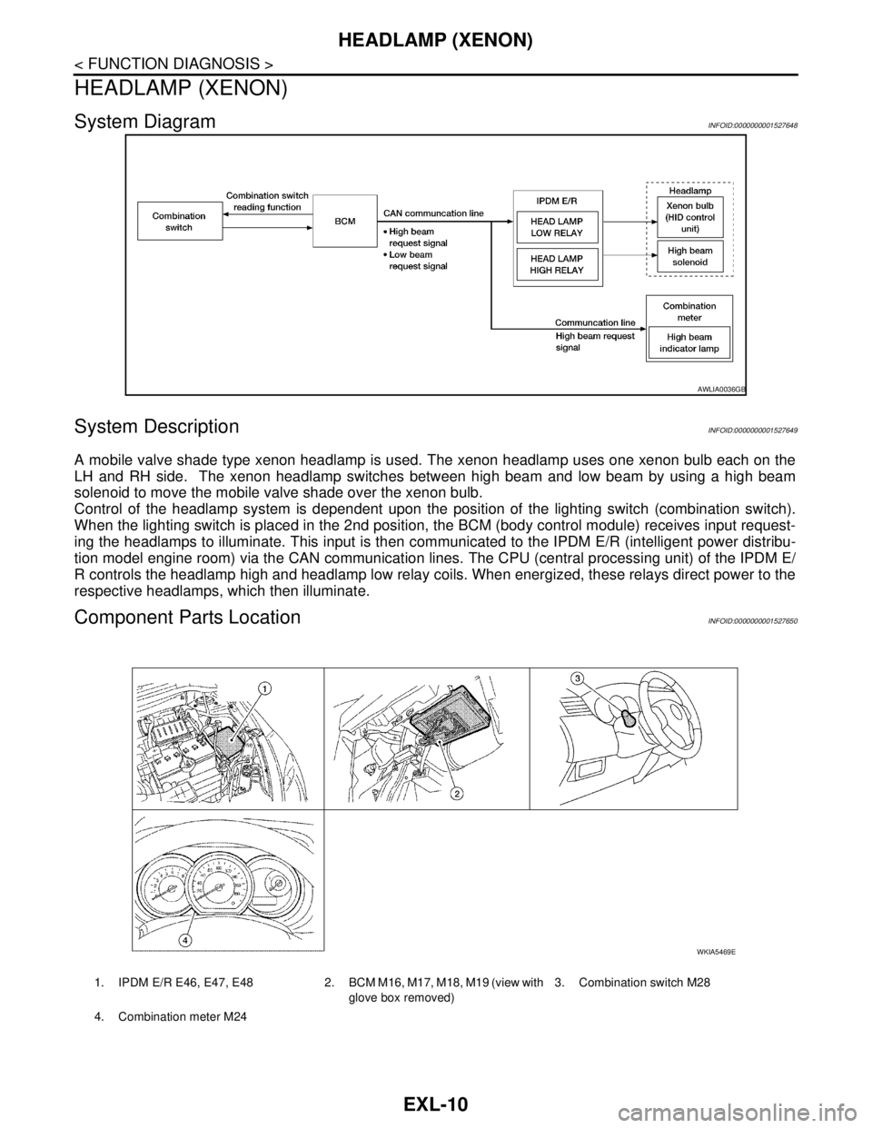
System DiagramINFOID:0000000001527648
System DescriptionINFOID:0000000001527649
A mobile valve shade type xenon headlamp is used. The xenon headlamp uses one xenon bulb each on the
LH and RH side. The xenon headlamp switches between high beam and low beam by using a high beam
solenoid to move the mobile valve shade over the xenon bulb.
Control of the headlamp system is dependent upon the position of the lighting switch (combination switch).
When the lighting switch is placed in the 2nd position, the BCM (body control module) receives input request-
ing the headlamps to illuminate. This input is then communicated to the IPDM E/R (intelligent power distribu-
tion model engine room) via the CAN communication lines. The CPU (central processing unit) of the IPDM E/
R controls the headlamp high and headlamp low relay coils. When energized, these relays direct power to the
respective headlamps, which then illuminate.
Component Parts LocationINFOID:0000000001527650
AWLIA0036GB
1. IPDM E/R E46, E47, E48 2. BCM M16, M17, M18, M19 (view with
glove box removed)3. Combination switch M28
4. Combination meter M24
WKIA5469E
Page 3012 of 5883

HEADLAMP (XENON)
EXL-11
< FUNCTION DIAGNOSIS >
C
D
E
F
G
H
I
J
K
MA
B
EXL
N
O
P
Component DescriptionINFOID:0000000001527651
Part Description
BCM• Monitors the combination switch position.
Requests the IPDM E/R (via CAN communication lines) to actuate the headlamp
high and low relays based on combination switch position .
Requests the combination meter (via CAN communication lines) to turn the high
beam indicator lamp ON.
IPDM E/RControls the integrated headlamp high and low relays based on input from the BCM
over the CAN communication lines.
Combination switch
(Lighting & turn signal switch)Refer to BCS-9, "
System Description".
Combination meter
(High beam indicator lamp)Controls the high beam indicator lamp ON during high beam operation based on input
from the BCM over the CAN communication lines.
Headlamp assem-
blyHID control unit Controls electricity flow through the xenon bulb.
Xenon bulbUses two tungsten electrodes and is filled with xenon gas and other metal halides.
Electricity flows between the electrodes to illuminate.
High beam solenoid Actuates the mobile valve shade to control high and low beam operation.
Mobile valve shadeWhen actuated by the high beam solenoid, it shades light output from the xenon bulb
for low beam operation and opens to allow more light output during high beam opera-
tion.
Page 3028 of 5883

DIAGNOSIS SYSTEM (BCM)
EXL-27
< FUNCTION DIAGNOSIS >
C
D
E
F
G
H
I
J
K
MA
B
EXL
N
O
P
ACTIVE TEST
FLASHER
FLASHER : CONSULT-III Function (BCM - FLASHER)INFOID:0000000001528979
WORK SUPPORT
DATA MONITOR
ACTIVE TEST
LIT-SEN FAIL [OK/NOTOK] The sensor status received from light & rain sensor with serial link
The serial link condition that BCM judges
AUT LIGHT SYS [ON/OFF] Auto light system status that BCM judges from the vehicle conditionMonitor item
[Unit]Description
Test item Operation Description
TAIL LAMPONTransmits the position light request signal to IPDM E/R with CAN com-
munication to turn the tail lamp ON.
OFF Stops the tail lamp request signal transmission.
HEAD LAMPHITransmits the high beam request signal with CAN communication to turn
the headlamp (HI).
LOTransmits the low beam request signal with CAN communication to turn
the headlamp (LO).
OFF Stops the high & low beam request signal transmission.
FR FOG LAMPONTransmits the front fog lights request signal to IPDM E/R with CAN com-
munication to turn the front fog lamp ON.
OFF Stops the front fog lights request signal transmission.
RR FOG LAMPON Outputs the voltage to turn the rear fog lamp ON.
Transmits the rear fog lamp status signal to the combination meter with
CAN communication to turn the rear fog lamp indicator lamp ON.
OFF Stops the voltage to turn the rear fog lamp OFF.
Stops the rear fog lamp status signal transmission.
DAYTIME RUNNING LIGHTONTransmits the day time running light request signal to IPDM E/R with
CAN communication to turn the each lamps ON.
OFF Stops the day time running light request signal transmission.
Work Item Description
HAZARD LAMP SETOperation MODE1 MODE2 MODE3
MODE4
Keyfob operation Lock Unlock Lock Unlock Lock Unlock Lock Unlock
Hazard lamp flash - - - Twice Once - Once Twice
Monitor Item
[Unit]Description
IGN ON SW [ON/OFF] Ignition switch (ON) status judged from IGN signal (ignition power supply)
HAZARD SW [ON/OFF] The switch status input from the hazard switch
TURN SIGNAL R [ON/OFF]
Each switch condition that BCM judges from the combination switch reading function
TURN SIGNAL L [ON/OFF]
TURN/L MNTR [ON/OFF] Displays status (one bulb out: ON/other: OFF) as judged from bulb signal
Page 3035 of 5883
EXL-34
< COMPONENT DIAGNOSIS >
HEADLAMP (HI) CIRCUIT
Is the measurement value normal?
YES >> GO TO 4
NO >> GO TO 3
3.CHECK HEADLAMP (HI) CIRCUIT FOR OPEN
1. Turn the ignition switch OFF.
2. Disconnect IPDM E/R connector.
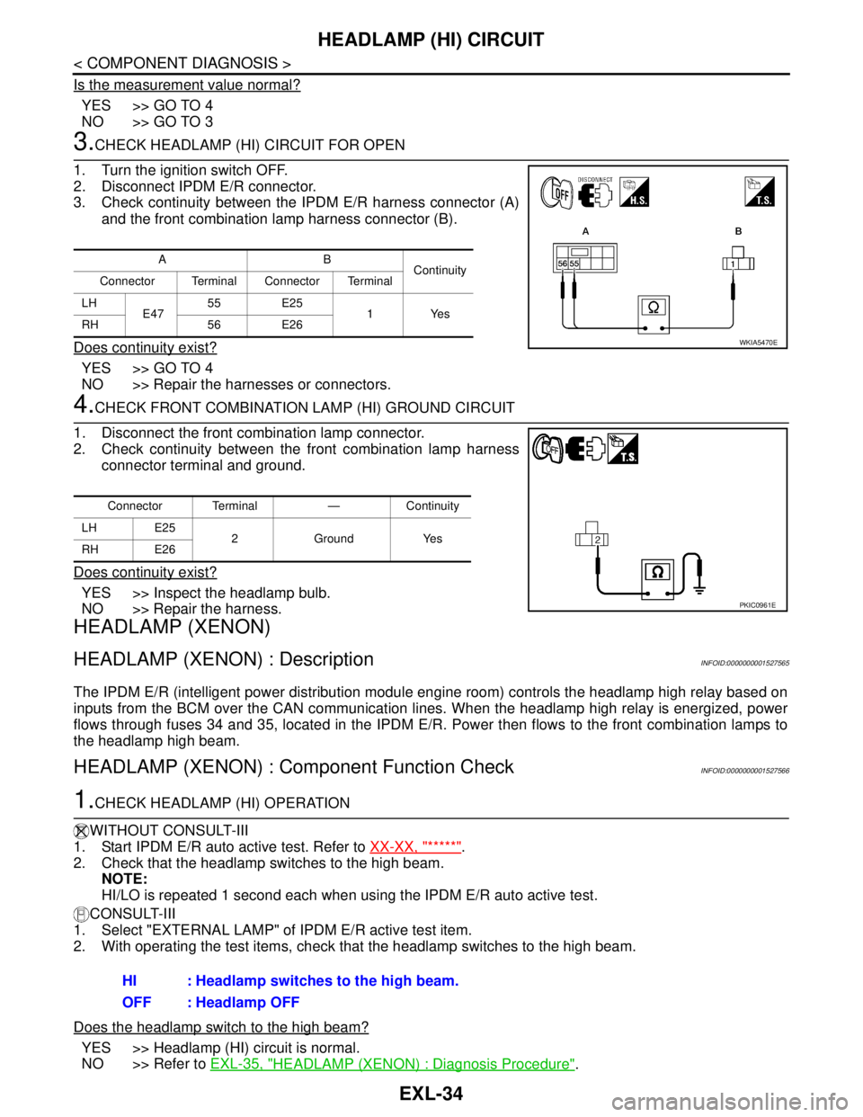
3. Check continuity between the IPDM E/R harness connector (A)
and the front combination lamp harness connector (B).
Does continuity exist?
YES >> GO TO 4
NO >> Repair the harnesses or connectors.
4.CHECK FRONT COMBINATION LAMP (HI) GROUND CIRCUIT
1. Disconnect the front combination lamp connector.
2. Check continuity between the front combination lamp harness
connector terminal and ground.
Does continuity exist?
YES >> Inspect the headlamp bulb.
NO >> Repair the harness.
HEADLAMP (XENON)
HEADLAMP (XENON) : DescriptionINFOID:0000000001527565
The IPDM E/R (intelligent power distribution module engine room) controls the headlamp high relay based on
inputs from the BCM over the CAN communication lines. When the headlamp high relay is energized, power
flows through fuses 34 and 35, located in the IPDM E/R. Power then flows to the front combination lamps to
the headlamp high beam.
HEADLAMP (XENON) : Component Function CheckINFOID:0000000001527566
1.CHECK HEADLAMP (HI) OPERATION
WITHOUT CONSULT-III
1. Start IPDM E/R auto active test. Refer to XX-XX, "*****"
.
2. Check that the headlamp switches to the high beam.
NOTE:
HI/LO is repeated 1 second each when using the IPDM E/R auto active test.
CONSULT-III
1. Select "EXTERNAL LAMP" of IPDM E/R active test item.
2. With operating the test items, check that the headlamp switches to the high beam.
Does the headlamp switch to the high beam?
YES >> Headlamp (HI) circuit is normal.
NO >> Refer to EXL-35, "
HEADLAMP (XENON) : Diagnosis Procedure".
AB
Continuity
Connector Terminal Connector Terminal
LH
E4755 E25
1Yes
RH 56 E26
WKIA5470E
Connector Terminal — Continuity
LH E25
2 Ground Yes
RH E26
PKIC0961E
HI : Headlamp switches to the high beam.
OFF : Headlamp OFF
Page 3036 of 5883
HEADLAMP (HI) CIRCUIT
EXL-35
< COMPONENT DIAGNOSIS >
C
D
E
F
G
H
I
J
K
MA
B
EXL
N
O
P
HEADLAMP (XENON) : Diagnosis ProcedureINFOID:0000000001527567
1.CHECK HEADLAMP (HI) FUSES
1. Turn the ignition switch OFF.
2. Check that the following fuses are not open.
Is the fuse open?
YES >> Repair the harness and replace the fuse.
NO >> GO TO 2
2.CHECK HEADLAMP (HI) OUTPUT VOLTAGE
CONSULT-III ACTIVE TEST
1. Turn the ignition switch OFF.
2. Disconnect the front combination lamp connector.
3. Turn the ignition switch ON.
4. Select "EXTERNAL LAMP" of IPDM E/R active test item.
5. With EXTERNAL LAMP ON, check the voltage between the combination lamp connector and ground.
Is the measurement value normal?
YES >> GO TO 4
NO >> GO TO 3
3.CHECK HEADLAMP (HI) CIRCUIT FOR OPEN
1. Turn the ignition switch OFF.
2. Disconnect IPDM E/R connector.
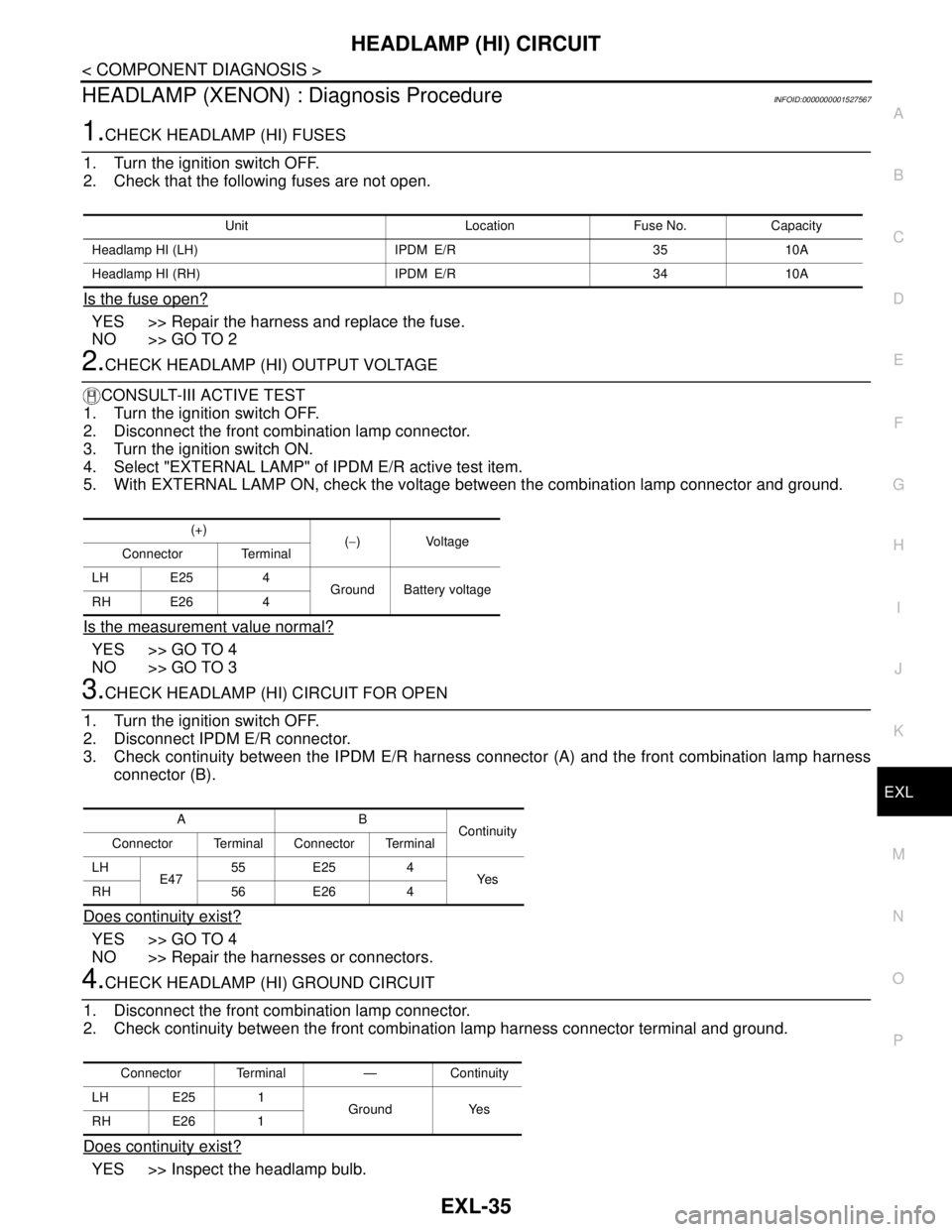
3. Check continuity between the IPDM E/R harness connector (A) and the front combination lamp harness
connector (B).
Does continuity exist?
YES >> GO TO 4
NO >> Repair the harnesses or connectors.
4.CHECK HEADLAMP (HI) GROUND CIRCUIT
1. Disconnect the front combination lamp connector.
2. Check continuity between the front combination lamp harness connector terminal and ground.
Does continuity exist?
YES >> Inspect the headlamp bulb.
Unit Location Fuse No. Capacity
Headlamp HI (LH) IPDM E/R 35 10A
Headlamp HI (RH) IPDM E/R 34 10A
(+)
(−)Voltage
Connector Terminal
LH E25 4
Ground Battery voltage
RH E26 4
AB
Continuity
Connector Terminal Connector Terminal
LH
E4755 E25 4
Ye s
RH 56 E26 4
Connector Terminal — Continuity
LH E25 1
Ground Yes
RH E26 1
Page 3039 of 5883
EXL-38
< COMPONENT DIAGNOSIS >
HEADLAMP (LO) CIRCUIT
Is the measurement value normal?
YES >> GO TO 4
NO >> GO TO 3
3.CHECK HEADLAMP (LO) CIRCUIT FOR OPEN
1. Turn the ignition switch OFF.
2. Disconnect IPDM E/R connector.
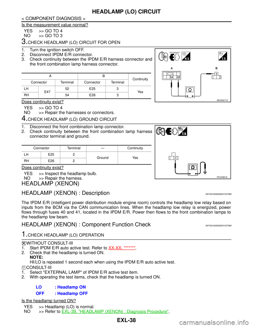
3. Check continuity between the IPDM E/R harness connector and
the front combination lamp harness connector.
Does continuity exist?
YES >> GO TO 4
NO >> Repair the harnesses or connectors.
4.CHECK HEADLAMP (LO) GROUND CIRCUIT
1. Disconnect the front combination lamp connector.
2. Check continuity between the front combination lamp harness
connector terminal and ground.
Does continuity exist?
YES >> Inspect the headlamp bulb.
NO >> Repair the harness.
HEADLAMP (XENON)
HEADLAMP (XENON) : DescriptionINFOID:0000000001527568
The IPDM E/R (intelligent power distribution module engine room) controls the headlamp low relay based on
inputs from the BCM via the CAN communication lines. When the headlamp low relay is energized, power
flows through fuses 40 and 41, located in the IPDM E/R. Power then flows to the front combination lamps to
the headlamp low beam.
HEADLAMP (XENON) : Component Function CheckINFOID:0000000001527569
1.CHECK HEADLAMP (LO) OPERATION
WITHOUT CONSULT-III
1. Start IPDM E/R auto active test. Refer to XX-XX, "*****"
.
2. Check that the headlamp is turned ON.
NOTE:
HI/LO is repeated 1 second each when using the IPDM E/R auto active test.
CONSULT-III
1. Select "EXTERNAL LAMP" of IPDM E/R active test item.
2. With operating the test items, check that the headlamp is turned ON.
Is the headlamp turned ON?
YES >> Headlamp (LO) is normal.
NO >> Refer to EXL-39, "
HEADLAMP (XENON) : Diagnosis Procedure".
AB
Continuity
Connector Terminal Connector Terminal
LH
E4752 E25 3
Ye s
RH 54 E26 3
WKIA5471E
Connector Terminal — Continuity
LH E25 2
Ground Yes
RH E26 2
PKIC0961E
LO : Headlamp ON
OFF : Headlamp OFF
Page 3040 of 5883
HEADLAMP (LO) CIRCUIT
EXL-39
< COMPONENT DIAGNOSIS >
C
D
E
F
G
H
I
J
K
MA
B
EXL
N
O
P
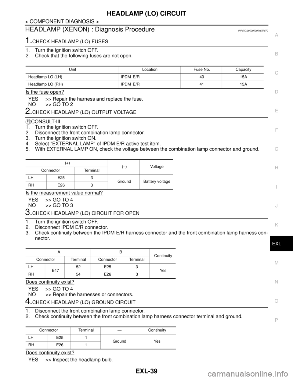
HEADLAMP (XENON) : Diagnosis ProcedureINFOID:0000000001527570
1.CHECK HEADLAMP (LO) FUSES
1. Turn the ignition switch OFF.
2. Check that the following fuses are not open.
Is the fuse open?
YES >> Repair the harness and replace the fuse.
NO >> GO TO 2
2.CHECK HEADLAMP (LO) OUTPUT VOLTAGE
CONSULT-III
1. Turn the ignition switch OFF.
2. Disconnect the front combination lamp connector.
3. Turn the ignition switch ON.
4. Select "EXTERNAL LAMP" of IPDM E/R active test item.
5. With EXTERNAL LAMP ON, check the voltage between the combination lamp connector and ground.
Is the measurement value normal?
YES >> GO TO 4
NO >> GO TO 3
3.CHECK HEADLAMP (LO) CIRCUIT FOR OPEN
1. Turn the ignition switch OFF.
2. Disconnect IPDM E/R connector.
3. Check continuity between the IPDM E/R harness connector and the front combination lamp harness con-
nector.
Does continuity exist?
YES >> GO TO 4
NO >> Repair the harnesses or connectors.
4.CHECK HEADLAMP (LO) GROUND CIRCUIT
1. Disconnect the front combination lamp connector.
2. Check continuity between the front combination lamp harness connector terminal and ground.
Does continuity exist?
YES >> Inspect the headlamp bulb.
Unit Location Fuse No. Capacity
Headlamp LO (LH) IPDM E/R 40 15A
Headlamp LO (RH) IPDM E/R 41 15A
(+)
(−)Voltage
Connector Terminal
LH E25 3
Ground Battery voltage
RH E26 3
AB
Continuity
Connector Terminal Connector Terminal
LH
E4752 E25 3
Ye s
RH 54 E26 3
Connector Terminal — Continuity
LH E25 1
Ground Yes
RH E26 1
Page 3043 of 5883

EXL-42
< COMPONENT DIAGNOSIS >
FRONT FOG LAMP CIRCUIT
Does continuity exist?
YES >> GO TO 4
NO >> Repair the harnesses or connectors.
4.CHECK FRONT FOG LAMP GROUND CIRCUIT
1. Disconnect the front fog lamp connector.
2. Check continuity between the front fog lamp harness connector terminal and ground.
Does continuity exist?
YES >> Inspect the fog lamp bulb.
NO >> Repair the harness.
AB
Continuity
Connector Terminal Connector Terminal
LH
E4750 E27
6Yes
RH 51 E28
Connector Terminal — Continuity
LH E27 7
Ground Yes
RH E28 7