Page 3011 of 5883
EXL-10
< FUNCTION DIAGNOSIS >
HEADLAMP (XENON)
HEADLAMP (XENON)
System DiagramINFOID:0000000001527648
System DescriptionINFOID:0000000001527649
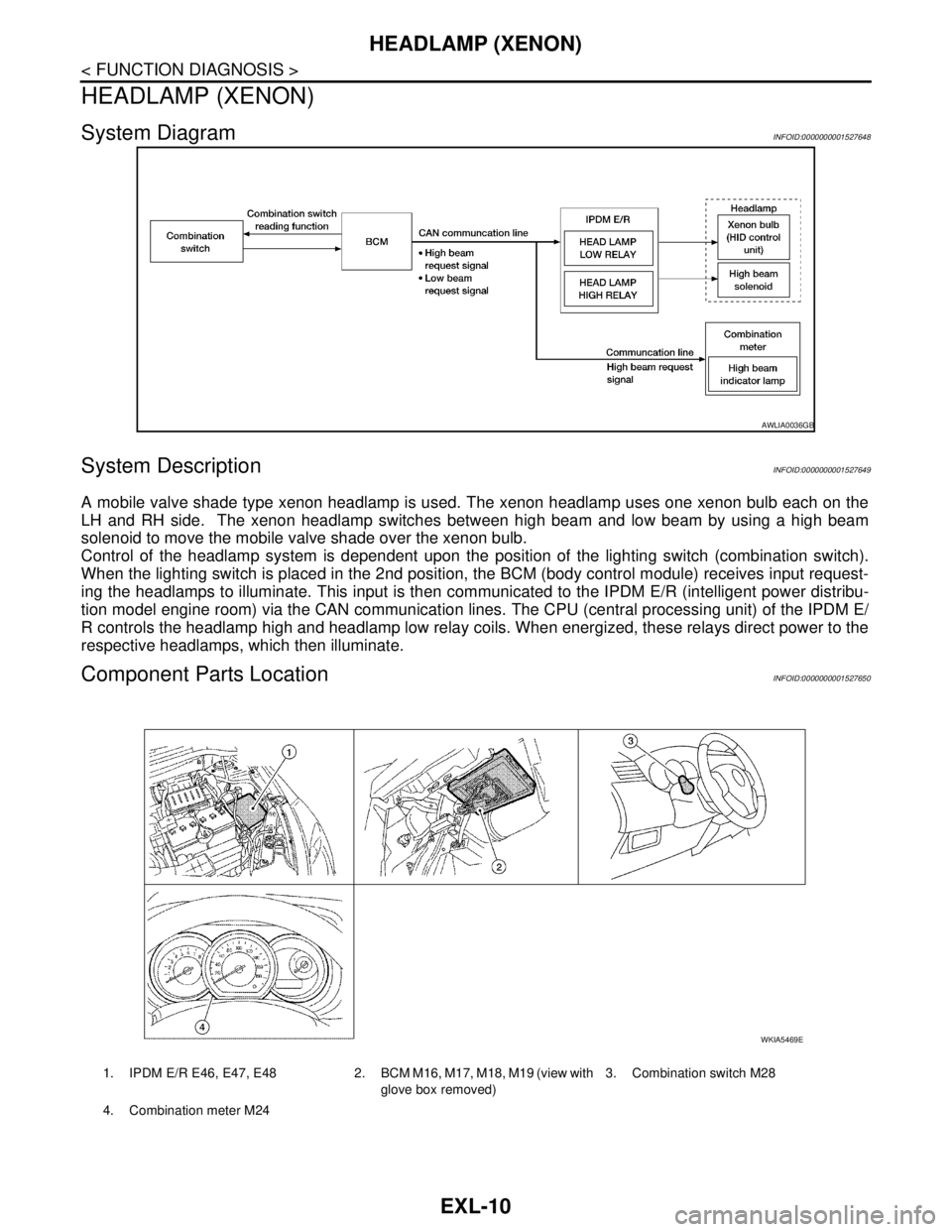
A mobile valve shade type xenon headlamp is used. The xenon headlamp uses one xenon bulb each on the
LH and RH side. The xenon headlamp switches between high beam and low beam by using a high beam
solenoid to move the mobile valve shade over the xenon bulb.
Control of the headlamp system is dependent upon the position of the lighting switch (combination switch).
When the lighting switch is placed in the 2nd position, the BCM (body control module) receives input request-
ing the headlamps to illuminate. This input is then communicated to the IPDM E/R (intelligent power distribu-
tion model engine room) via the CAN communication lines. The CPU (central processing unit) of the IPDM E/
R controls the headlamp high and headlamp low relay coils. When energized, these relays direct power to the
respective headlamps, which then illuminate.
Component Parts LocationINFOID:0000000001527650
AWLIA0036GB
1. IPDM E/R E46, E47, E48 2. BCM M16, M17, M18, M19 (view with
glove box removed)3. Combination switch M28
4. Combination meter M24
WKIA5469E
Page 3013 of 5883
EXL-12
< FUNCTION DIAGNOSIS >
AUTO LIGHT SYSTEM
AUTO LIGHT SYSTEM
System DiagramINFOID:0000000001523233
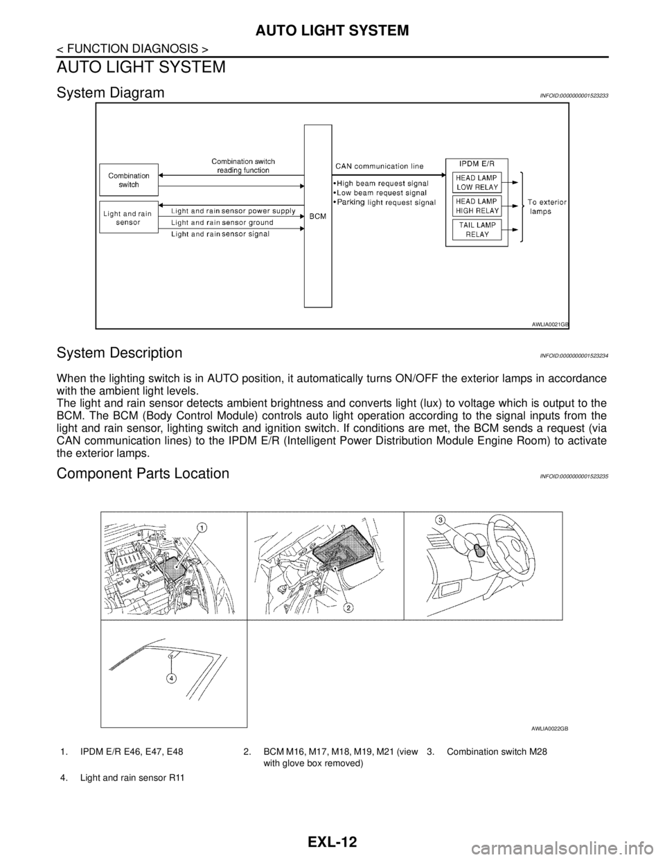
System DescriptionINFOID:0000000001523234
When the lighting switch is in AUTO position, it automatically turns ON/OFF the exterior lamps in accordance
with the ambient light levels.
The light and rain sensor detects ambient brightness and converts light (lux) to voltage which is output to the
BCM. The BCM (Body Control Module) controls auto light operation according to the signal inputs from the
light and rain sensor, lighting switch and ignition switch. If conditions are met, the BCM sends a request (via
CAN communication lines) to the IPDM E/R (Intelligent Power Distribution Module Engine Room) to activate
the exterior lamps.
Component Parts LocationINFOID:0000000001523235
AWLIA0021GB
1. IPDM E/R E46, E47, E48 2. BCM M16, M17, M18, M19, M21 (view
with glove box removed)3. Combination switch M28
4. Light and rain sensor R11
AWLIA0022GB
Page 3015 of 5883
EXL-14
< FUNCTION DIAGNOSIS >
HEADLAMP AIMING SYSTEM (MANUAL)
HEADLAMP AIMING SYSTEM (MANUAL)
System DiagramINFOID:0000000001527662
System DescriptionINFOID:0000000001527663
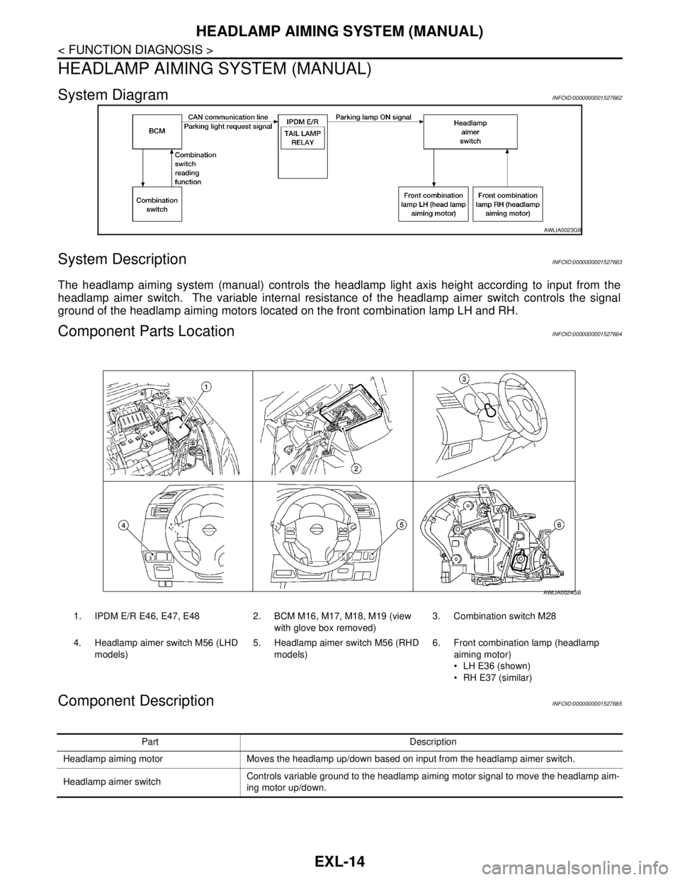
The headlamp aiming system (manual) controls the headlamp light axis height according to input from the
headlamp aimer switch. The variable internal resistance of the headlamp aimer switch controls the signal
ground of the headlamp aiming motors located on the front combination lamp LH and RH.
Component Parts LocationINFOID:0000000001527664
Component DescriptionINFOID:0000000001527665
AWLIA0023GB
1. IPDM E/R E46, E47, E48 2. BCM M16, M17, M18, M19 (view
with glove box removed)3. Combination switch M28
4. Headlamp aimer switch M56 (LHD
models)5. Headlamp aimer switch M56 (RHD
models)6. Front combination lamp (headlamp
aiming motor)
LH E36 (shown)
RH E37 (similar)
AWLIA0024GB
Part Description
Headlamp aiming motor Moves the headlamp up/down based on input from the headlamp aimer switch.
Headlamp aimer switchControls variable ground to the headlamp aiming motor signal to move the headlamp aim-
ing motor up/down.
Page 3016 of 5883
HEADLAMP AIMING SYSTEM (AUTOMATIC)
EXL-15
< FUNCTION DIAGNOSIS >
C
D
E
F
G
H
I
J
K
MA
B
EXL
N
O
P
HEADLAMP AIMING SYSTEM (AUTOMATIC)
System DiagramINFOID:0000000001527658
System DescriptionINFOID:0000000001527659
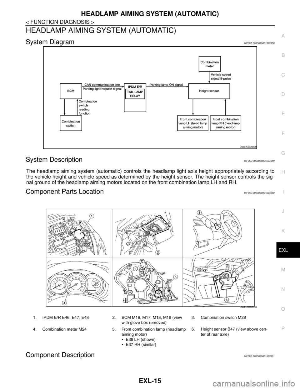
The headlamp aiming system (automatic) controls the headlamp light axis height appropriately according to
the vehicle height and vehicle speed as determined by the height sensor. The height sensor controls the sig-
nal ground of the headlamp aiming motors located on the front combination lamp LH and RH.
Component Parts LocationINFOID:0000000001527660
Component DescriptionINFOID:0000000001527661
AWLIA0025GB
1. IPDM E/R E46, E47, E48 2. BCM M16, M17, M18, M19 (view
with glove box removed)3. Combination switch M28
4. Combination meter M24 5. Front combination lamp (headlamp
aiming motor)
E36 LH (shown)
E37 RH (similar)6. Height sensor B47 (view above cen-
ter of rear axle)
AWLIA0026GB
Page 3018 of 5883
DAYTIME LIGHT SYSTEM
EXL-17
< FUNCTION DIAGNOSIS >
C
D
E
F
G
H
I
J
K
MA
B
EXL
N
O
P
DAYTIME LIGHT SYSTEM
System DiagramINFOID:0000000001527654
System DescriptionINFOID:0000000001527655
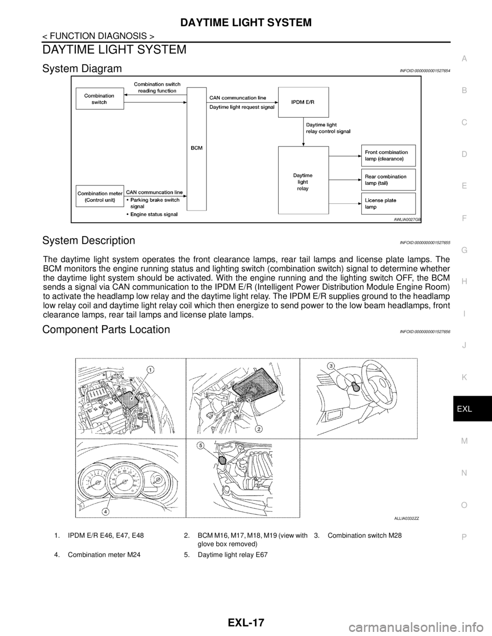
The daytime light system operates the front clearance lamps, rear tail lamps and license plate lamps. The
BCM monitors the engine running status and lighting switch (combination switch) signal to determine whether
the daytime light system should be activated. With the engine running and the lighting switch OFF, the BCM
sends a signal via CAN communication to the IPDM E/R (Intelligent Power Distribution Module Engine Room)
to activate the headlamp low relay and the daytime light relay. The IPDM E/R supplies ground to the headlamp
low relay coil and daytime light relay coil which then energize to send power to the low beam headlamps, front
clearance lamps, rear tail lamps and license plate lamps.
Component Parts LocationINFOID:0000000001527656
AWLIA0027GB
1. IPDM E/R E46, E47, E48 2. BCM M16, M17, M18, M19 (view with
glove box removed)3. Combination switch M28
4. Combination meter M24 5. Daytime light relay E67
ALLIA0332ZZ
Page 3020 of 5883
FRONT FOG LAMP
EXL-19
< FUNCTION DIAGNOSIS >
C
D
E
F
G
H
I
J
K
MA
B
EXL
N
O
P
FRONT FOG LAMP
System DiagramINFOID:0000000001523237
System DescriptionINFOID:0000000001523238
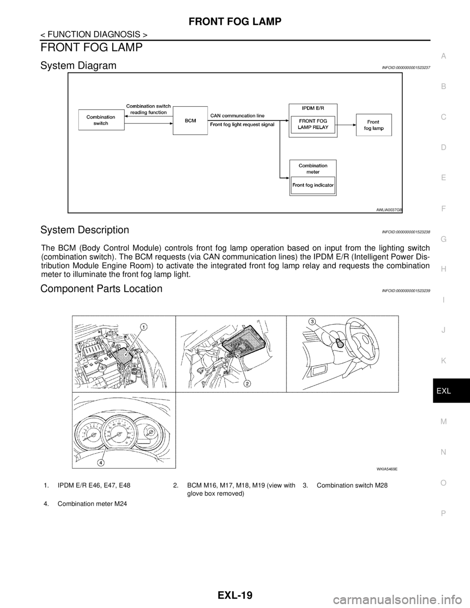
The BCM (Body Control Module) controls front fog lamp operation based on input from the lighting switch
(combination switch). The BCM requests (via CAN communication lines) the IPDM E/R (Intelligent Power Dis-
tribution Module Engine Room) to activate the integrated front fog lamp relay and requests the combination
meter to illuminate the front fog lamp light.
Component Parts LocationINFOID:0000000001523239
AWLIA0037GB
1. IPDM E/R E46, E47, E48 2. BCM M16, M17, M18, M19 (view with
glove box removed)3. Combination switch M28
4. Combination meter M24
WKIA5469E
Page 3022 of 5883
REAR FOG LAMP
EXL-21
< FUNCTION DIAGNOSIS >
C
D
E
F
G
H
I
J
K
MA
B
EXL
N
O
P
REAR FOG LAMP
System DiagramINFOID:0000000001527666
System DescriptionINFOID:0000000001527667
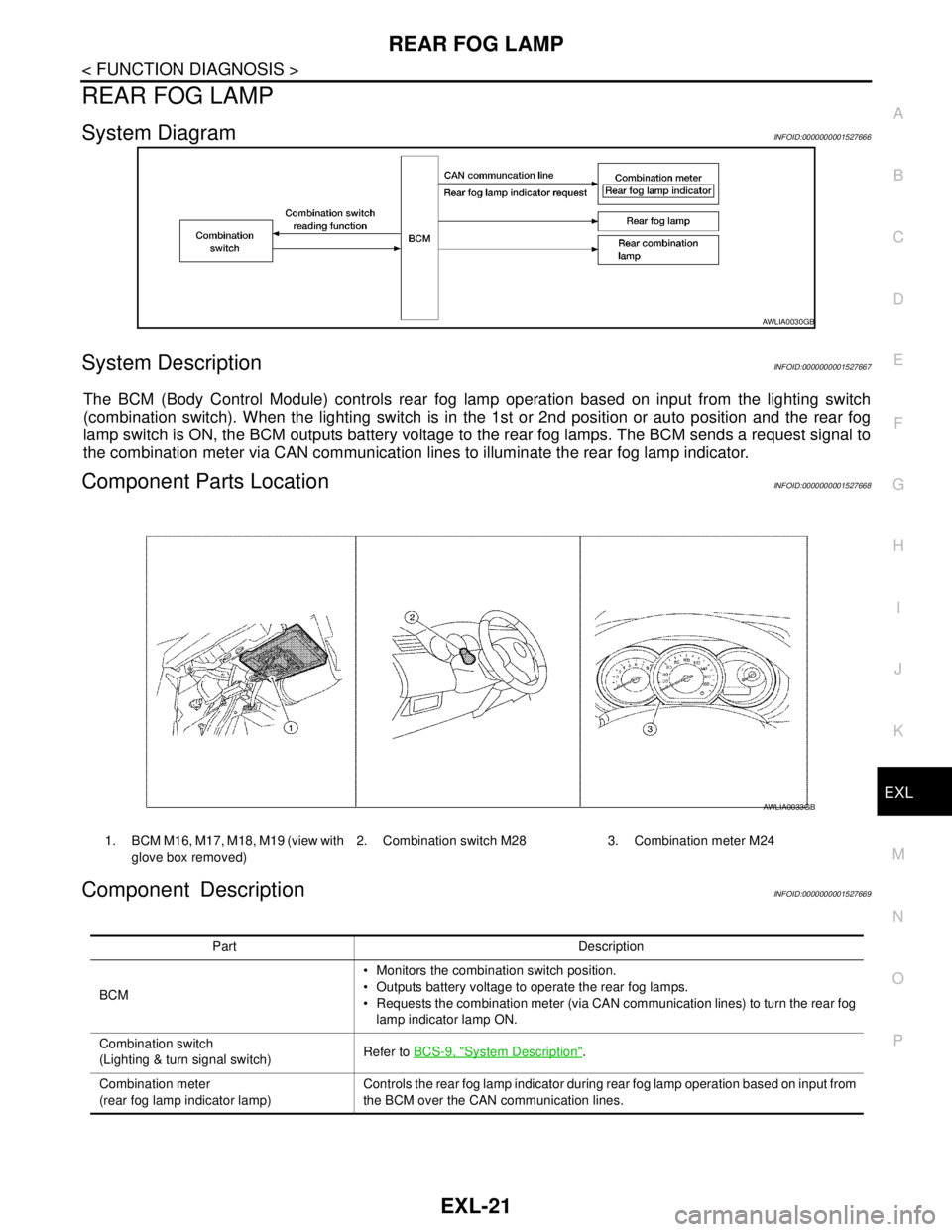
The BCM (Body Control Module) controls rear fog lamp operation based on input from the lighting switch
(combination switch). When the lighting switch is in the 1st or 2nd position or auto position and the rear fog
lamp switch is ON, the BCM outputs battery voltage to the rear fog lamps. The BCM sends a request signal to
the combination meter via CAN communication lines to illuminate the rear fog lamp indicator.
Component Parts LocationINFOID:0000000001527668
Component DescriptionINFOID:0000000001527669
AWLIA0030GB
1. BCM M16, M17, M18, M19 (view with
glove box removed)2. Combination switch M28 3. Combination meter M24
AWLIA0033GB
Part Description
BCM Monitors the combination switch position.
Outputs battery voltage to operate the rear fog lamps.
Requests the combination meter (via CAN communication lines) to turn the rear fog
lamp indicator lamp ON.
Combination switch
(Lighting & turn signal switch)Refer to BCS-9, "
System Description".
Combination meter
(rear fog lamp indicator lamp)Controls the rear fog lamp indicator during rear fog lamp operation based on input from
the BCM over the CAN communication lines.
Page 3023 of 5883
EXL-22
< FUNCTION DIAGNOSIS >
TURN SIGNAL AND HAZARD WARNING LAMPS
TURN SIGNAL AND HAZARD WARNING LAMPS
System DiagramINFOID:0000000001523241
System DescriptionINFOID:0000000001523242
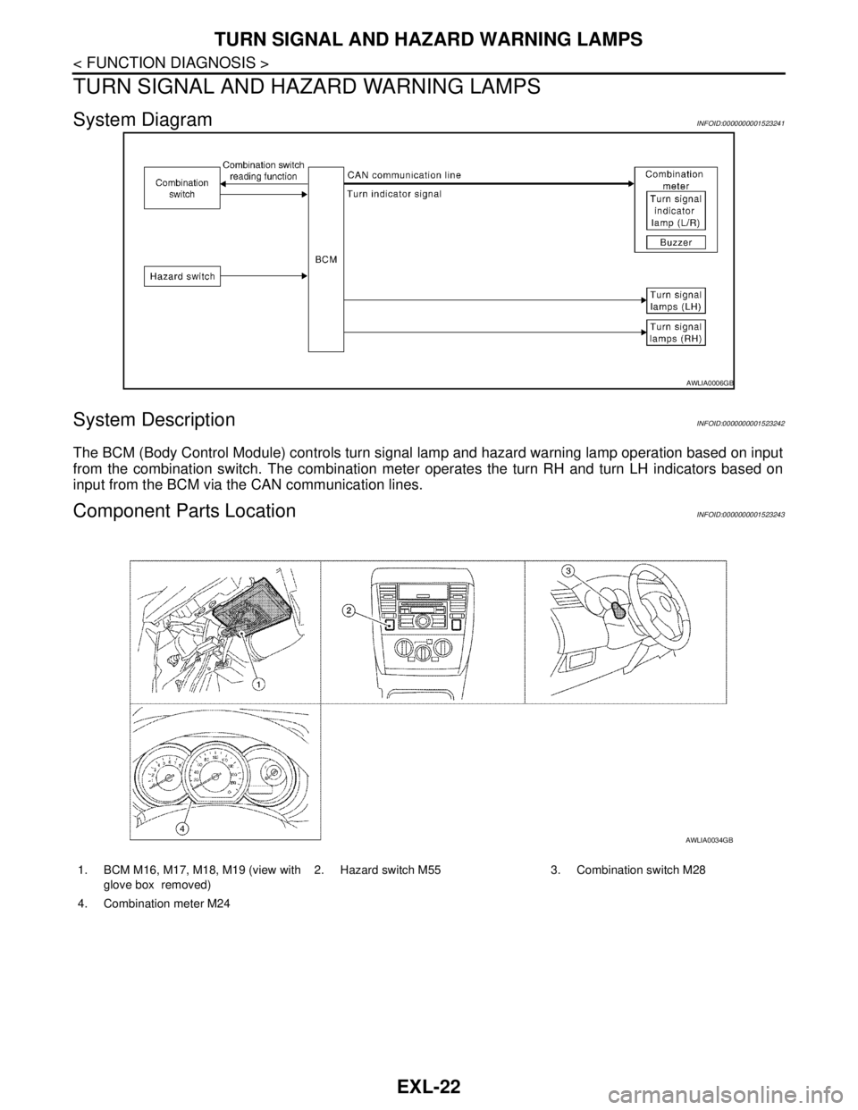
The BCM (Body Control Module) controls turn signal lamp and hazard warning lamp operation based on input
from the combination switch. The combination meter operates the turn RH and turn LH indicators based on
input from the BCM via the CAN communication lines.
Component Parts LocationINFOID:0000000001523243
AWLIA0006GB
1. BCM M16, M17, M18, M19 (view with
glove box removed)2. Hazard switch M55 3. Combination switch M28
4. Combination meter M24
AWLIA0034GB