2007 NISSAN TIIDA Cooling
[x] Cancel search: CoolingPage 545 of 5883
![NISSAN TIIDA 2007 Service Repair Manual CO-64
< ON-VEHICLE REPAIR >[K9K]
COOLING FAN
COOLING FAN
Exploded ViewINFOID:0000000001381594
Removal and InstallationINFOID:0000000001381595
REMOVAL
1. Remove engine undercover using power tool.
2. D NISSAN TIIDA 2007 Service Repair Manual CO-64
< ON-VEHICLE REPAIR >[K9K]
COOLING FAN
COOLING FAN
Exploded ViewINFOID:0000000001381594
Removal and InstallationINFOID:0000000001381595
REMOVAL
1. Remove engine undercover using power tool.
2. D](/manual-img/5/57395/w960_57395-544.png)
CO-64
< ON-VEHICLE REPAIR >[K9K]
COOLING FAN
COOLING FAN
Exploded ViewINFOID:0000000001381594
Removal and InstallationINFOID:0000000001381595
REMOVAL
1. Remove engine undercover using power tool.
2. Drain engine coolant. Refer to CO-58, "
Draining".
3. Remove air duct (inlet). Refer to EM-269, "
Exploded View".
4. Disconnect reservoir tank hoses and remove reservoir tank.
5. Remove radiator hose (upper). Refer to CO-62, "
Exploded View".
6. Disconnect harness connector for cooling fan control module and fan motor, and move harness aside.
7. Remove cooling fan assembly.
CAUTION:
Be careful not to damage or scratch on radiator core.
INSTALLATION
Installation is in the reverse order of removal.
CAUTION:
Only use genuine parts for fan shroud bolt and observe the specified torque (to prevent radiator from
being damaged).
NOTE:
Cooling fan is controlled by ECM. For details, refer to CO-52, "
EngineCoolingSystem".
1. Fan shroud 2. Cooling fan control module 3. Fan motor
4. Cooling fan
A. Reverse screw
: Vehicle front
ALBIA0424GB
Page 546 of 5883
![NISSAN TIIDA 2007 Service Repair Manual COOLING FAN
CO-65
< ON-VEHICLE REPAIR >[K9K]
C
D
E
F
G
H
I
J
K
L
MA
CO
N
P O
Disassembly and AssemblyINFOID:0000000001381596
DISASSEMBLY
1. Remove cooling fan control module from fan shroud.
CAUTION:
NISSAN TIIDA 2007 Service Repair Manual COOLING FAN
CO-65
< ON-VEHICLE REPAIR >[K9K]
C
D
E
F
G
H
I
J
K
L
MA
CO
N
P O
Disassembly and AssemblyINFOID:0000000001381596
DISASSEMBLY
1. Remove cooling fan control module from fan shroud.
CAUTION:](/manual-img/5/57395/w960_57395-545.png)
COOLING FAN
CO-65
< ON-VEHICLE REPAIR >[K9K]
C
D
E
F
G
H
I
J
K
L
MA
CO
N
P O
Disassembly and AssemblyINFOID:0000000001381596
DISASSEMBLY
1. Remove cooling fan control module from fan shroud.
CAUTION:
Handle carefully to avoid dropping and shocks.
2. Remove cooling fan mounting nut, and then remove the cooling fan.
CAUTION:
Reverse nut is used for the fan attachment. When removing or attaching, turn the nut the opposite
direction from a normal nut.
3. Remove fan motor.
ASSEMBLY
Assembly is in the reverse order of disassembly.
Apply thread locking sealant on fan motor shaft.
InspectionINFOID:0000000001381597
INSPECTION AFTER DISASSEMBLY
Cooling Fan
Inspect cooling fan for crack or unusual bend.
If anything is found, replace cooling fan.
Page 1351 of 5883
EC-2
Component Parts Location ...................................63
Component Description .........................................68
CAN COMMUNICATION ...................................69
System Description .................................................69
COOLING FAN CONTROL ...............................70
System Diagram .....................................................70
System Description .................................................70
Component Parts Location ...................................72
Component Description ..........................................77
EVAPORATIVE EMISSION SYSTEM ...............78
System Diagram .....................................................78
System Description .................................................80
Component Parts Location ...................................81
Component Description .........................................86
INTAKE VALVE TIMING CONTROL .................87
System Diagram .....................................................87
System Description .................................................87
Component Parts Location ...................................88
Component Description ..........................................93
ON BOARD DIAGNOSTIC (OBD) SYSTEM .....94
Diagnosis Description .............................................94
CONSULT-III Function ..........................................107
Diagnosis Tool Function ......................................114
COMPONENT DIAGNOSIS .......................116
TROUBLE DIAGNOSIS - SPECIFICATION
VALUE .............................................................
116
Description .............................................................116
Component Function Check ..................................116
Diagnosis Procedure .............................................117
POWER SUPPLY AND GROUND CIRCUIT ...124
Diagnosis Procedure .............................................124
U1000, U1001 CAN COMM CIRCUIT .............128
Description .............................................................128
DTC Logic ..............................................................128
Diagnosis Procedure .............................................128
U1010 CONTROL UNIT (CAN) .......................129
Description .............................................................129
DTC Logic ..............................................................129
Diagnosis Procedure .............................................129
P0011 IVT CONTROL ......................................130
DTC Logic ..............................................................130
Diagnosis Procedure .............................................131
Component Inspection ...........................................132
P0102, P0103 MAF SENSOR ..........................134
Description .............................................................134
DTC Logic ..............................................................134
Diagnosis Procedure .............................................135
Component Inspection ...........................................136
P0112, P0113 IAT SENSOR ............................139
Description ............................................................139
DTC Logic .............................................................139
Diagnosis Procedure .............................................140
Component Inspection ..........................................140
P0117, P0118 ECT SENSOR ...........................142
Description ............................................................142
DTC Logic .............................................................142
Diagnosis Procedure .............................................143
Component Inspection ..........................................143
P0122, P0123 TP SENSOR ..............................145
Description ............................................................145
DTC Logic .............................................................145
Diagnosis Procedure .............................................145
Component Inspection ..........................................147
Special Repair Requirement .................................147
P0132 HO2S1 ...................................................148
Description ............................................................148
DTC Logic .............................................................148
Diagnosis Procedure .............................................149
Component Inspection ..........................................150
P0133 HO2S1 ...................................................152
Description ............................................................152
DTC Logic .............................................................152
Diagnosis Procedure .............................................154
Component Inspection ..........................................155
P0134 HO2S1 ...................................................158
Description ............................................................158
DTC Logic .............................................................158
Diagnosis Procedure .............................................159
Component Inspection ..........................................160
P0135 HO2S1 HEATER ...................................163
Description ............................................................163
DTC Logic .............................................................163
Diagnosis Procedure .............................................163
Component Inspection ..........................................164
P0138 HO2S2 ...................................................166
Description ............................................................166
DTC Logic .............................................................166
Diagnosis Procedure .............................................167
Component Inspection ..........................................168
P0139 HO2S2 ...................................................170
Description ............................................................170
DTC Logic .............................................................170
Component Function Check .................................172
Diagnosis Procedure .............................................173
Component Inspection ..........................................174
P0141 HO2S2 HEATER ...................................176
Description ............................................................176
DTC Logic .............................................................176
Diagnosis Procedure .............................................176
Component Inspection ..........................................178
Page 1353 of 5883
EC-4
Description .............................................................250
DTC Logic ..............................................................250
Component Function Check ..................................252
Diagnosis Procedure .............................................253
Component Inspection ...........................................254
P1212 TCS COMMUNICATION LINE .............256
Description .............................................................256
DTC Logic ..............................................................256
Diagnosis Procedure .............................................256
P1217 ENGINE OVER TEMPERATURE .........257
DTC Logic ..............................................................257
Component Function Check ..................................257
Diagnosis Procedure .............................................258
P1225 TP SENSOR .........................................261
Description .............................................................261
DTC Logic ..............................................................261
Diagnosis Procedure .............................................261
Special Repair Requirement ..................................262
P1226 TP SENSOR .........................................263
Description .............................................................263
DTC Logic ..............................................................263
Diagnosis Procedure .............................................263
Special Repair Requirement ..................................264
P1229 SENSOR POWER SUPPLY .................265
DTC Logic ..............................................................265
Diagnosis Procedure .............................................265
P1564 ASCD STEERING SWITCH .................267
Description .............................................................267
DTC Logic ..............................................................267
Diagnosis Procedure .............................................267
Component Inspection ...........................................269
P1572 ASCD BRAKE SWITCH .......................270
Description .............................................................270
DTC Logic ..............................................................270
Diagnosis Procedure .............................................271
Component Inspection (ASCD Brake Switch) .......275
Component Inspection (ASCD Clutch Switch) .......276
Component Inspection (Stop Lamp Switch) ..........276
P1574 ASCD VEHICLE SPEED SENSOR ......278
Description .............................................................278
DTC Logic ..............................................................278
Diagnosis Procedure .............................................278
P1706 PNP SWITCH .......................................280
Description .............................................................280
DTC Logic ..............................................................280
Component Function Check ..................................281
Diagnosis Procedure .............................................281
P1805 BRAKE SWITCH ..................................283
Description .............................................................283
DTC Logic ..............................................................283
Diagnosis Procedure .............................................283
Component Inspection (Stop Lamp Switch) ..........284
P2122, P2123 APP SENSOR ...........................286
Description ............................................................286
DTC Logic .............................................................286
Diagnosis Procedure .............................................286
Component Inspection ..........................................288
Special Repair Requirement .................................288
P2127, P2128 APP SENSOR ...........................290
Description ............................................................290
DTC Logic .............................................................290
Diagnosis Procedure .............................................290
Component Inspection ..........................................293
Special Repair Requirement .................................293
P2135 TP SENSOR ..........................................294
Description ............................................................294
DTC Logic .............................................................294
Diagnosis Procedure .............................................294
Component Inspection ..........................................296
Special Repair Requirement .................................296
P2138 APP SENSOR .......................................297
Description ............................................................297
DTC Logic .............................................................297
Diagnosis Procedure .............................................297
Component Inspection ..........................................300
Special Repair Requirement .................................300
ASCD BRAKE SWITCH ...................................302
Description ............................................................302
Component Function Check .................................302
Diagnosis Procedure .............................................302
Component Inspection (ASCD Brake Switch) .......305
Component Inspection (ASCD Clutch Switch) ......305
ASCD INDICATOR ...........................................306
Description ............................................................306
Component Function Check .................................306
Diagnosis Procedure .............................................306
COOLING FAN .................................................307
Description ............................................................307
Component Function Check .................................307
Diagnosis Procedure .............................................307
Component Inspection ..........................................309
ELECTRICAL LOAD SIGNAL ..........................311
Description ............................................................311
Component Function Check .................................311
Diagnosis Procedure .............................................311
FUEL INJECTOR ..............................................313
Description ............................................................313
Component Function Check .................................313
Diagnosis Procedure .............................................313
Component Inspection ..........................................314
FUEL PUMP .....................................................316
Description ............................................................316
Page 1355 of 5883
EC-6
IDLE AIR VOLUME LEARNING : Special Repair
Requirement ..........................................................
390
MIXTURE RATIO SELF-LEARNING VALUE
CLEAR .....................................................................
392
MIXTURE RATIO SELF-LEARNING VALUE
CLEAR : Description ..............................................
392
MIXTURE RATIO SELF-LEARNING VALUE
CLEAR : Special Repair Requirement ...................
392
FUNCTION DIAGNOSIS ............................393
ENGINE CONTROL SYSTEM .........................393
System Diagram ...................................................393
System Description ................................................394
Component Parts Location ..................................394
Component Description .........................................399
MULTIPORT FUEL INJECTION SYSTEM ......401
System Diagram ...................................................401
System Description ................................................401
Component Parts Location ..................................404
Component Description .........................................409
ELECTRIC IGNITION SYSTEM .......................410
System Diagram ...................................................410
System Description ................................................410
Component Parts Location ..................................411
Component Description .........................................416
AIR CONDITIONING CUT CONTROL ............417
System Diagram ....................................................417
System Description ................................................417
Component Parts Location ..................................418
Component Description .........................................423
AUTOMATIC SPEED CONTROL DEVICE
(ASCD) .............................................................
424
System Diagram ....................................................424
System Description ................................................424
Component Parts Location ..................................426
Component Description ........................................431
CAN COMMUNICATION .................................432
System Description ................................................432
COOLING FAN CONTROL .............................433
System Diagram ....................................................433
System Description ................................................433
Component Parts Location ..................................435
Component Description .........................................440
EVAPORATIVE EMISSION SYSTEM .............441
System Diagram ....................................................441
System Description ................................................443
Component Parts Location ..................................444
Component Description ........................................449
INTAKE VALVE TIMING CONTROL ...............450
System Diagram ....................................................450
System Description ................................................450
Component Parts Location ..................................451
Component Description ........................................456
DIAGNOSIS SYSTEM (ECM) ...........................457
Diagnosis Description ...........................................457
CONSULT-III Function ..........................................462
COMPONENT DIAGNOSIS ......................469
TROUBLE DIAGNOSIS - SPECIFICATION
VALUE ..............................................................
469
Description ............................................................469
Component Function Check .................................469
Diagnosis Procedure .............................................470
POWER SUPPLY AND GROUND CIRCUIT ....477
Diagnosis Procedure .............................................477
U1000, U1001 CAN COMM CIRCUIT ..............481
Description ............................................................481
DTC Logic .............................................................481
Diagnosis Procedure .............................................481
U1010 CONTROL UNIT (CAN) ........................482
Description ............................................................482
DTC Logic .............................................................482
Diagnosis Procedure .............................................482
P0011 IVT CONTROL ......................................483
DTC Logic .............................................................483
Component Function Check .................................484
Diagnosis Procedure .............................................484
Component Inspection ..........................................486
P0102, P0103 MAF SENSOR ..........................487
Description ............................................................487
DTC Logic .............................................................487
Diagnosis Procedure .............................................488
Component Inspection ..........................................489
P0117, P0118 ECT SENSOR ...........................492
Description ............................................................492
DTC Logic .............................................................492
Diagnosis Procedure .............................................493
Component Inspection ..........................................493
P0122, P0123 TP SENSOR ..............................495
Description ............................................................495
DTC Logic .............................................................495
Diagnosis Procedure .............................................495
Component Inspection ..........................................497
Special Repair Requirement .................................497
P0132 HO2S1 ...................................................498
Description ............................................................498
DTC Logic .............................................................498
Diagnosis Procedure .............................................499
Component Inspection ..........................................500
P0134 HO2S1 ...................................................502
Description ............................................................502
DTC Logic .............................................................502
Page 1357 of 5883
EC-8
Diagnosis Procedure .............................................564
P1706 PNP SWITCH .......................................566
Description .............................................................566
DTC Logic ..............................................................566
Component Function Check ..................................567
Diagnosis Procedure .............................................567
P1805 BRAKE SWITCH ..................................569
Description .............................................................569
DTC Logic ..............................................................569
Diagnosis Procedure .............................................569
Component Inspection (Stop Lamp Switch) ..........570
P2122, P2123 APP SENSOR ..........................572
Description .............................................................572
DTC Logic ..............................................................572
Diagnosis Procedure .............................................572
Component Inspection ...........................................574
Special Repair Requirement ..................................574
P2127, P2128 APP SENSOR ..........................576
Description .............................................................576
DTC Logic ..............................................................576
Diagnosis Procedure .............................................576
Component Inspection ...........................................579
Special Repair Requirement ..................................579
P2135 TP SENSOR .........................................580
Description .............................................................580
DTC Logic ..............................................................580
Diagnosis Procedure .............................................580
Component Inspection ...........................................582
Special Repair Requirement ..................................582
P2138 APP SENSOR ......................................583
Description .............................................................583
DTC Logic ..............................................................583
Diagnosis Procedure .............................................583
Component Inspection ...........................................586
Special Repair Requirement ..................................586
ASCD BRAKE SWITCH ..................................588
Description .............................................................588
Component Function Check ..................................588
Diagnosis Procedure .............................................588
Component Inspection (ASCD Brake Switch) .......591
Component Inspection (ASCD Clutch Switch) .......591
ASCD INDICATOR ..........................................592
Description .............................................................592
Component Function Check ..................................592
Diagnosis Procedure .............................................592
COOLING FAN ................................................593
Description .............................................................593
Component Function Check ..................................593
Diagnosis Procedure .............................................593
Component Inspection ...........................................595
ELECTRICAL LOAD SIGNAL .........................597
Description ............................................................597
Component Function Check .................................597
Diagnosis Procedure .............................................597
EVAP CANISTER PURGE VOLUME CON-
TROL SOLENOID VALVE ................................
599
Description ............................................................599
Component Function Check .................................599
Diagnosis Procedure .............................................599
Component Inspection ..........................................601
FUEL INJECTOR ..............................................602
Description ............................................................602
Component Function Check .................................602
Diagnosis Procedure .............................................602
Component Inspection ..........................................603
FUEL PUMP .....................................................605
Description ............................................................605
Component Function Check .................................605
Diagnosis Procedure .............................................605
Component Inspection (Fuel Pump) .....................607
HO2S1 ..............................................................608
Description ............................................................608
Component Function Check .................................608
Diagnosis Procedure .............................................609
Component Inspection ..........................................611
HO2S1 HEATER ...............................................613
Description ............................................................613
Component Function Check .................................613
Diagnosis Procedure .............................................613
Component Inspection ..........................................615
HO2S2 ..............................................................616
Description ............................................................616
Component Function Check .................................616
Diagnosis Procedure .............................................617
Component Inspection ..........................................618
HO2S2 HEATER ...............................................620
Description ............................................................620
Component Function Check .................................620
Diagnosis Procedure .............................................620
Component Inspection ..........................................622
IAT SENSOR ....................................................623
Description ............................................................623
Component Function Check .................................623
Diagnosis Procedure .............................................623
Component Inspection ..........................................624
IGNITION SIGNAL ............................................625
Description ............................................................625
Component Function Check .................................625
Diagnosis Procedure .............................................625
Component Inspection (Ignition Coil with Power
Transistor) .............................................................
628
Component Inspection (Condenser) .....................628
Page 1359 of 5883
EC-10
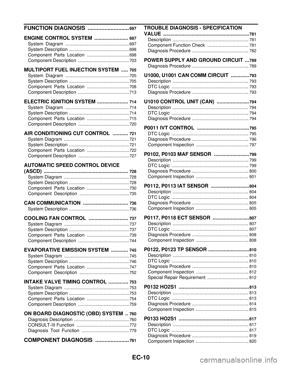
FUNCTION DIAGNOSIS ............................697
ENGINE CONTROL SYSTEM .........................697
System Diagram ...................................................697
System Description ................................................698
Component Parts Location ..................................698
Component Description .........................................703
MULTIPORT FUEL INJECTION SYSTEM ......705
System Diagram ...................................................705
System Description ................................................705
Component Parts Location ..................................708
Component Description .........................................713
ELECTRIC IGNITION SYSTEM .......................714
System Diagram ...................................................714
System Description ................................................714
Component Parts Location ..................................715
Component Description .........................................720
AIR CONDITIONING CUT CONTROL ............721
System Diagram ....................................................721
System Description ................................................721
Component Parts Location ..................................722
Component Description .........................................727
AUTOMATIC SPEED CONTROL DEVICE
(ASCD) .............................................................
728
System Diagram ....................................................728
System Description ................................................728
Component Parts Location ..................................730
Component Description ........................................735
CAN COMMUNICATION .................................736
System Description ................................................736
COOLING FAN CONTROL .............................737
System Diagram ....................................................737
System Description ................................................737
Component Parts Location ..................................739
Component Description .........................................744
EVAPORATIVE EMISSION SYSTEM .............745
System Diagram ....................................................745
System Description ................................................746
Component Parts Location ..................................747
Component Description ........................................752
INTAKE VALVE TIMING CONTROL ...............753
System Diagram ....................................................753
System Description ................................................753
Component Parts Location ..................................754
Component Description .........................................759
ON BOARD DIAGNOSTIC (OBD) SYSTEM ...760
Diagnosis Description ............................................760
CONSULT-III Function ..........................................772
Diagnosis Tool Function ......................................779
COMPONENT DIAGNOSIS .......................781
TROUBLE DIAGNOSIS - SPECIFICATION
VALUE ..............................................................
781
Description ............................................................781
Component Function Check .................................781
Diagnosis Procedure .............................................782
POWER SUPPLY AND GROUND CIRCUIT ....789
Diagnosis Procedure .............................................789
U1000, U1001 CAN COMM CIRCUIT ..............793
Description ............................................................793
DTC Logic .............................................................793
Diagnosis Procedure .............................................793
U1010 CONTROL UNIT (CAN) ........................794
Description ............................................................794
DTC Logic .............................................................794
Diagnosis Procedure .............................................794
P0011 IVT CONTROL ......................................795
DTC Logic .............................................................795
Diagnosis Procedure .............................................796
Component Inspection ..........................................797
P0102, P0103 MAF SENSOR ..........................799
Description ............................................................799
DTC Logic .............................................................799
Diagnosis Procedure .............................................800
Component Inspection ..........................................801
P0112, P0113 IAT SENSOR ............................804
Description ............................................................804
DTC Logic .............................................................804
Diagnosis Procedure .............................................805
Component Inspection ..........................................805
P0117, P0118 ECT SENSOR ...........................807
Description ............................................................807
DTC Logic .............................................................807
Diagnosis Procedure .............................................808
Component Inspection ..........................................808
P0122, P0123 TP SENSOR ..............................810
Description ............................................................810
DTC Logic .............................................................810
Diagnosis Procedure .............................................810
Component Inspection ..........................................812
Special Repair Requirement .................................812
P0132 HO2S1 ...................................................813
Description ............................................................813
DTC Logic .............................................................813
Diagnosis Procedure .............................................814
Component Inspection ..........................................815
P0133 HO2S1 ...................................................817
Description ............................................................817
DTC Logic .............................................................817
Diagnosis Procedure .............................................819
Component Inspection ..........................................820
Page 1362 of 5883
EC-13
C
D
E
F
G
H
I
J
K
L
M
ECA
N
O
P
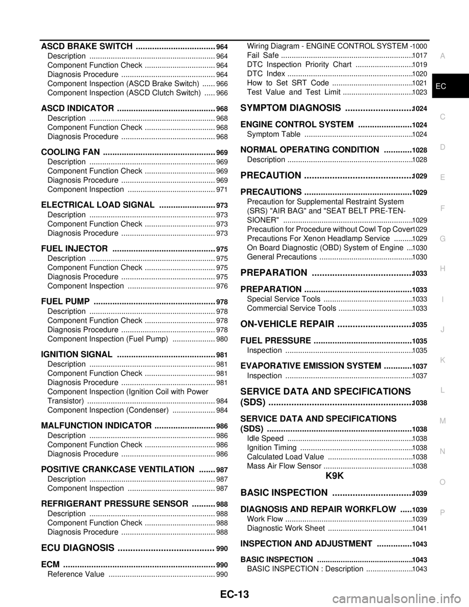
ASCD BRAKE SWITCH ...................................964
Description ............................................................964
Component Function Check ..................................964
Diagnosis Procedure .............................................964
Component Inspection (ASCD Brake Switch) .......966
Component Inspection (ASCD Clutch Switch) ......966
ASCD INDICATOR ...........................................968
Description ............................................................968
Component Function Check ..................................968
Diagnosis Procedure .............................................968
COOLING FAN .................................................969
Description ............................................................969
Component Function Check ..................................969
Diagnosis Procedure .............................................969
Component Inspection ..........................................971
ELECTRICAL LOAD SIGNAL .........................973
Description ............................................................973
Component Function Check ..................................973
Diagnosis Procedure .............................................973
FUEL INJECTOR .............................................975
Description ............................................................975
Component Function Check ..................................975
Diagnosis Procedure .............................................975
Component Inspection ..........................................976
FUEL PUMP .....................................................978
Description ............................................................978
Component Function Check ..................................978
Diagnosis Procedure .............................................978
Component Inspection (Fuel Pump) .....................980
IGNITION SIGNAL ...........................................981
Description ............................................................981
Component Function Check ..................................981
Diagnosis Procedure .............................................981
Component Inspection (Ignition Coil with Power
Transistor) .............................................................
984
Component Inspection (Condenser) .....................984
MALFUNCTION INDICATOR ...........................986
Description ............................................................986
Component Function Check ..................................986
Diagnosis Procedure .............................................986
POSITIVE CRANKCASE VENTILATION ........987
Description ............................................................987
Component Inspection ..........................................987
REFRIGERANT PRESSURE SENSOR ...........988
Description ............................................................988
Component Function Check ..................................988
Diagnosis Procedure .............................................988
ECU DIAGNOSIS .......................................990
ECM ..................................................................990
Reference Value ...................................................990
Wiring Diagram - ENGINE CONTROL SYSTEM - 1000
Fail Safe ..............................................................1017
DTC Inspection Priority Chart ...........................1019
DTC Index ...........................................................1020
How to Set SRT Code ......................................1021
Test Value and Test Limit .................................1023
SYMPTOM DIAGNOSIS ...........................1024
ENGINE CONTROL SYSTEM .......................1024
Symptom Table ...................................................1024
NORMAL OPERATING CONDITION ............1028
Description ...........................................................1028
PRECAUTION ...........................................1029
PRECAUTIONS ..............................................1029
Precaution for Supplemental Restraint System
(SRS) "AIR BAG" and "SEAT BELT PRE-TEN-
SIONER" .............................................................
1029
Precaution for Procedure without Cowl Top Cover 1029
Precautions For Xenon Headlamp Service .........1029
On Board Diagnostic (OBD) System of Engine ...1030
General Precautions ............................................1030
PREPARATION ........................................1033
PREPARATION ..............................................1033
Special Service Tools ..........................................1033
Commercial Service Tools ...................................1033
ON-VEHICLE REPAIR ..............................1035
FUEL PRESSURE ..........................................1035
Inspection ............................................................1035
EVAPORATIVE EMISSION SYSTEM ............1037
Inspection ............................................................1037
SERVICE DATA AND SPECIFICATIONS
(SDS) .........................................................
1038
SERVICE DATA AND SPECIFICATIONS
(SDS) ..............................................................
1038
Idle Speed ...........................................................1038
Ignition Timing .....................................................1038
Calculated Load Value ........................................1038
Mass Air Flow Sensor ..........................................1038
K9K
BASIC INSPECTION ................................
1039
DIAGNOSIS AND REPAIR WORKFLOW .....1039
Work Flow ............................................................1039
Diagnostic Work Sheet ........................................1041
INSPECTION AND ADJUSTMENT ...............1043
BASIC INSPECTION .............................................1043
BASIC INSPECTION : Description ......................1043