Page 4277 of 5883

ENGINE MAINTENANCE (MR18DE)
MA-37
< ON-VEHICLE MAINTENANCE >
C
D
E
F
G
H
I
J
K
L
MB
MAN
OA
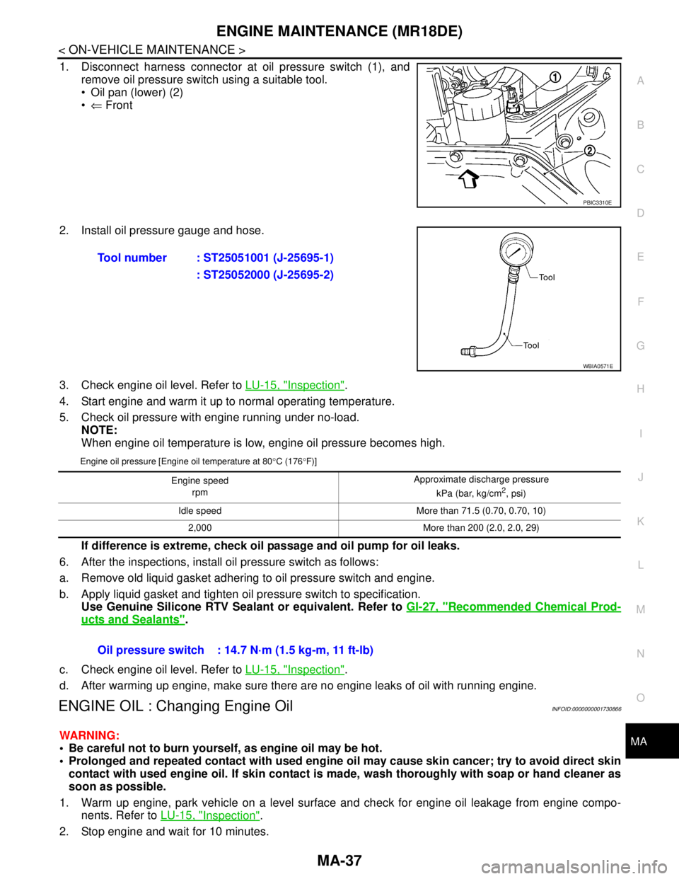
1. Disconnect harness connector at oil pressure switch (1), and
remove oil pressure switch using a suitable tool.
Oil pan (lower) (2)
⇐ Front
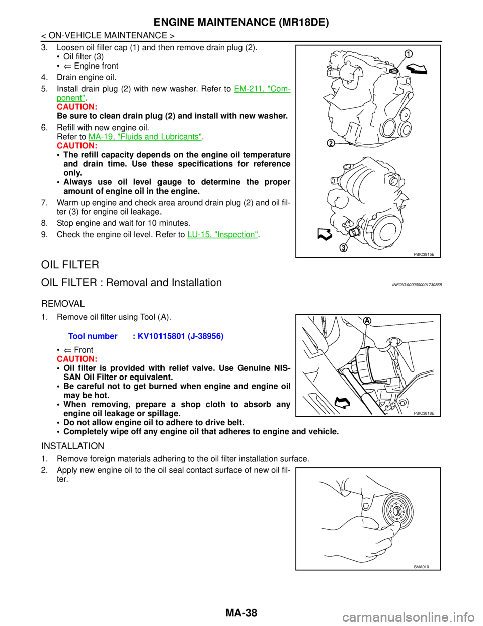
2. Install oil pressure gauge and hose.
3. Check engine oil level. Refer to LU-15, "
Inspection".
4. Start engine and warm it up to normal operating temperature.
5. Check oil pressure with engine running under no-load.
NOTE:
When engine oil temperature is low, engine oil pressure becomes high.
Engine oil pressure [Engine oil temperature at 80°C (176°F)]
If difference is extreme, check oil passage and oil pump for oil leaks.
6. After the inspections, install oil pressure switch as follows:
a. Remove old liquid gasket adhering to oil pressure switch and engine.
b. Apply liquid gasket and tighten oil pressure switch to specification.
Use Genuine Silicone RTV Sealant or equivalent. Refer to GI-27, "
Recommended Chemical Prod-
ucts and Sealants".
c. Check engine oil level. Refer to LU-15, "
Inspection".
d. After warming up engine, make sure there are no engine leaks of oil with running engine.
ENGINE OIL : Changing Engine OilINFOID:0000000001730866
WARNING:
Be careful not to burn yourself, as engine oil may be hot.
Prolonged and repeated contact with used engine oil may cause skin cancer; try to avoid direct skin
contact with used engine oil. If skin contact is made, wash thoroughly with soap or hand cleaner as
soon as possible.
1. Warm up engine, park vehicle on a level surface and check for engine oil leakage from engine compo-
nents. Refer to LU-15, "
Inspection".
2. Stop engine and wait for 10 minutes.
PBIC3310E
Tool number : ST25051001 (J-25695-1)
: ST25052000 (J-25695-2)
WBIA0571E
Engine speed
rpm Approximate discharge pressure
kPa (bar, kg/cm2, psi)
Idle speed More than 71.5 (0.70, 0.70, 10)
2,000 More than 200 (2.0, 2.0, 29)
Oil pressure switch : 14.7 N·m (1.5 kg-m, 11 ft-lb)
Page 4278 of 5883

MA-38
< ON-VEHICLE MAINTENANCE >
ENGINE MAINTENANCE (MR18DE)
3. Loosen oil filler cap (1) and then remove drain plug (2).
Oil filter (3)
⇐ Engine front
4. Drain engine oil.
5. Install drain plug (2) with new washer. Refer to EM-211, "
Com-
ponent".
CAUTION:
Be sure to clean drain plug (2) and install with new washer.
6. Refill with new engine oil.
Refer to MA-19, "
Fluids and Lubricants".
CAUTION:
The refill capacity depends on the engine oil temperature
and drain time. Use these specifications for reference
only.
Always use oil level gauge to determine the proper
amount of engine oil in the engine.
7. Warm up engine and check area around drain plug (2) and oil fil-
ter (3) for engine oil leakage.
8. Stop engine and wait for 10 minutes.
9. Check the engine oil level. Refer to LU-15, "
Inspection".
OIL FILTER
OIL FILTER : Removal and InstallationINFOID:0000000001730868
REMOVAL
1. Remove oil filter using Tool (A).
⇐ Front
CAUTION:
Oil filter is provided with relief valve. Use Genuine NIS-
SAN Oil Filter or equivalent.
Be careful not to get burned when engine and engine oil
may be hot.
When removing, prepare a shop cloth to absorb any
engine oil leakage or spillage.
Do not allow engine oil to adhere to drive belt.
Completely wipe off any engine oil that adheres to engine and vehicle.
INSTALLATION
1. Remove foreign materials adhering to the oil filter installation surface.
2. Apply new engine oil to the oil seal contact surface of new oil fil-
ter.
PBIC3915E
Tool number : KV10115801 (J-38956)
PBIC3818E
SMA010
Page 4279 of 5883
ENGINE MAINTENANCE (MR18DE)
MA-39
< ON-VEHICLE MAINTENANCE >
C
D
E
F
G
H
I
J
K
L
MB
MAN
OA
3. Screw oil filter manually until it touches the installation surface,
then tighten it by 2/3 turn. Or tighten to specification.
INSPECTION AFTER INSTALLATION
1. Check the engine oil level. Refer to LU-6, "Inspection".
2. Start engine, and make sure there is no leaks of engine oil.
3. Stop engine and wait for 10 minutes.
4. Check the engine oil level and adjust engine oil. Refer to LU-6, "
Inspection".
OIL FILTER : InspectionINFOID:0000000001277633
INSPECTION AFTER INSTALLATION
1. Check the engine oil level. Refer to MA-36, "ENGINE OIL : Inspection".
2. Start the engine, and check there is no leak of engine oil.
3. Stop the engine and wait for 10 minutes.
4. Check the engine oil level, and adjust the level. Refer to MA-36, "
ENGINE OIL : Inspection".
SPARK PLUG
Oil filter: : 17.7 N·m (1.8 kg-m, 13 ft-lb)
SMA229B
Page 4280 of 5883
MA-40
< ON-VEHICLE MAINTENANCE >
ENGINE MAINTENANCE (MR18DE)
SPARK PLUG : Component
INFOID:0000000001730863
SPARK PLUG : Removal and InstallationINFOID:0000000001730864
REMOVAL
1. Remove intake manifold. Refer to EM-156, "Removal and Installation".
2. Remove ignition coil.
CAUTION:
Handle it carefully and avoid impacts.
Never disassemble.
3. Remove spark plug using suitable tool.
CAUTION:
Never drop or shock it.
1. PCV hose 2. Rocker cover 3. Spark plug
4. Ignition coil 5. PCV hose 6. PCV valve
7. O-ring 8. Gasket
A. To air duct B. Refer to MA-40
. C. To intake manifold
PBIC3536J
PBIC3871E
Page 4281 of 5883
ENGINE MAINTENANCE (MR18DE)
MA-41
< ON-VEHICLE MAINTENANCE >
C
D
E
F
G
H
I
J
K
L
MB
MAN
OA
INSPECTION AFTER REMOVAL
CAUTION:
Never drop or shock spark plug.
Checking and adjusting spark plug gap is not required
between change intervals.
If spark plug tip is covered with carbon, a spark plug cleaner may be used.
Never use wire brush for cleaning spark plug.
INSTALLATION
1. Install spark plug using suitable tool.
CAUTION:
Never drop or shock it.
2. Install ignition coil.
CAUTION:
Handle it carefully and avoid impacts.
Never disassemble.
3. Install intake manifold. Refer to EM-156, "
Removal and Installation".
EVAP VAPOR LINES
EVAP VAPOR LINES : InspectionINFOID:0000000001277636
Refer to FL-10, "Removal and Installation"
SMA806CA
Cleaner air pressure
: Less than 588 kPa (5.88 bar, 6 kg/cm2, 85 psi)
Cleaning time : Less than 20 seconds
SMA773C
Plug type : Platinum tipped
Make : NGK
Part number : PLZKAR6A-11
Gap (nominal) : 1.1 mm (0.043 in)
PBIC3871E
Page 4282 of 5883

MA-42
< ON-VEHICLE MAINTENANCE >
ENGINE MAINTENANCE (K9K)
ENGINE MAINTENANCE (K9K)
DRIVE BELTS
DRIVE BELTS : Exploded ViewINFOID:0000000001730873
DRIVE BELTS : Inspection and AdjustmentINFOID:0000000001730874
INSPECTION
WARNING:
Be sure to perform when the engine is stopped.
1. Inspect drive belt for cracks, fraying, wear and oil. Replace drive belt if necessary.
2. Manually evaluate the drive belt tension (tension cannot be measured using frequency meter).
3. Replace drive belt when tension is beyond normal operating limit.
CAUTION:
Auto-tensioner must be replaced with a new one when the belt is replaced.
ADJUSTMENT
Belt tensioning is not necessary, as it is automatically adjusted by auto-tensioner.
ENGINE COOLANT
ENGINE COOLANT : InspectionINFOID:0000000001730880
LEVEL CHECK
Check if the reservoir tank engine coolant level is within the “MIN”
to “MAX” range when engine is cool.
Adjust the engine coolant level as necessary.
CHECKING COOLING SYSTEM FOR LEAKS
E1BIA0021ZZ
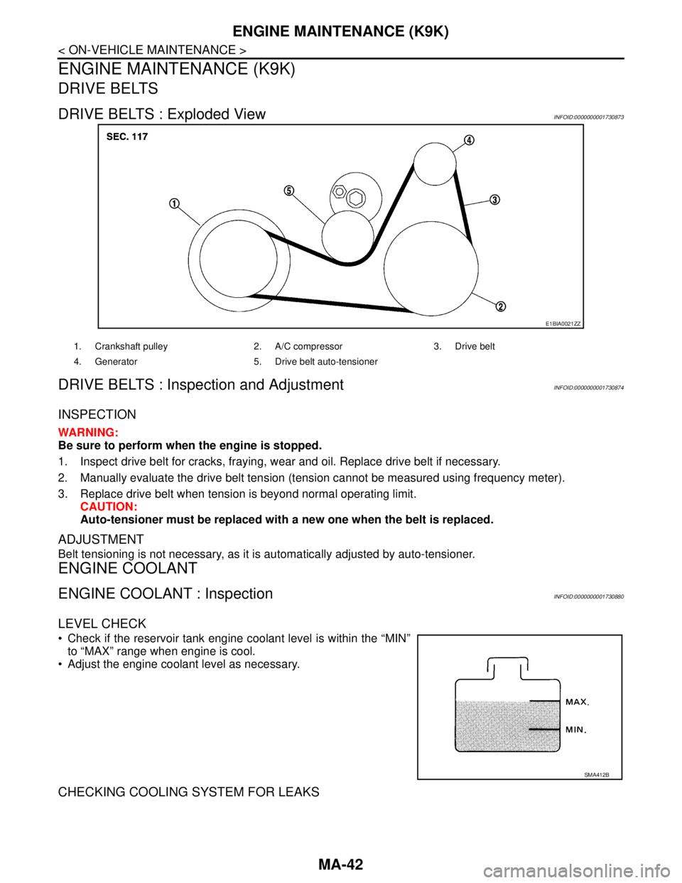
1. Crankshaft pulley 2. A/C compressor 3. Drive belt
4. Generator 5. Drive belt auto-tensioner
SMA412B
Page 4284 of 5883

MA-44
< ON-VEHICLE MAINTENANCE >
ENGINE MAINTENANCE (K9K)
4. Start engine without closing reservoir tank cap and keep engine racing at 1,500 rpm for about 2-3 minutes.
If necessary, pour engine coolant up to MAX level.
If coolant overflows reservoir tank hole, install filler cap.
Watch engine coolant temperature gauge so as not overheat the engine.
WARNING:
Be careful not to be scaled with hot engine coolant or vacuum pump when operating.
Radiator fan blade can start at any time and cause personal injuries.
5. Turn off the engine and loosen air relief plug until coolant spills from air relief hole.
6. Close the air relief plug and run the engine at 2,000 rpm until the upper hose becomes hot and radiator
fan operates. Leave the engine running approximately 5 minutes at idle speed and check for sound of
coolant flow while running engine from idle up to 3,000 rpm.
Sound may be noticeable at heater water cock.
7. If sound is heard, bleed air from cooling system by repeating steps 4 to 6 until coolant level no longer
drops.
Check the radiator lower hose for any signs of leakage.
8. Turn off the engine and let it cool down.
Cool down using a fan to reduce the time.
9. After cooling period, loosen the air relief plug and check if coolant spills from the air relief hole. if not,
remove the air relief plug until the coolant spills, and then close the relief air plug. Bleed air from cooling
system by repeating steps 6 to 10 until the coolant spills immediately.
10. Check the engine coolant level when engine is cool and refill to MAX level line if the level is lower.
Clean excess coolant from engine.
11. Check that the reservoir tank cap is tightened.
ENGINE COOLANT : FlushingINFOID:0000000001730883
1. Install reservoir tank if removed.
If water drain plug on cylinder block is removed, close and tighten it. Refer to EM-314, "
Exploded
View".
2. Fill reservoir tank with water until water spills from the air relief hole, then close air relief plug. Reinstall
reservoir tank cap.
3. Run engine and warm it up to normal operating temperature.
4. Rev engine two or three times under no-load.
5. Stop engine and wait until it cools down.
6. Drain water.
7. Repeat steps 1 through 6 until clear water begins to drain from radiator.
8. Blow compressed air into cooling circuit through the reservoir tank valve hole to drain all the water.
RADIATOR
RADIATOR : Checking Radiator CapINFOID:0000000001730884
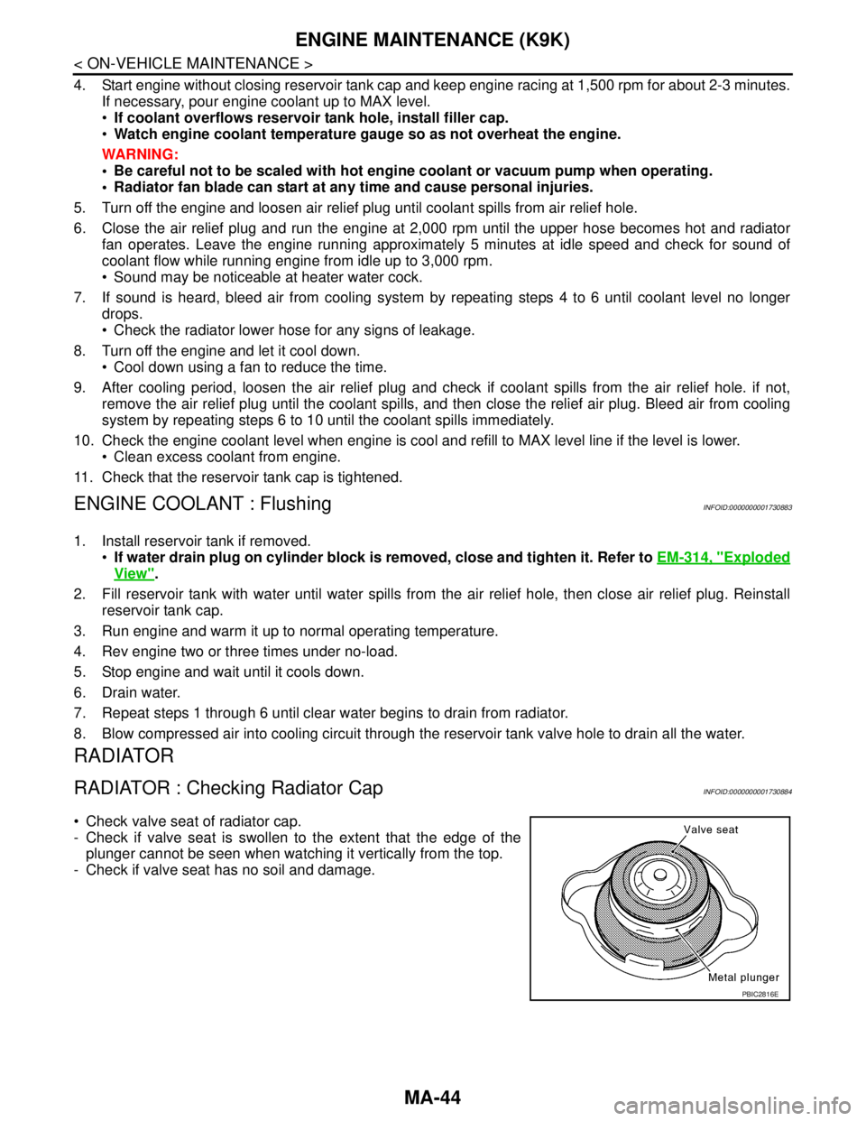
Check valve seat of radiator cap.
- Check if valve seat is swollen to the extent that the edge of the
plunger cannot be seen when watching it vertically from the top.
- Check if valve seat has no soil and damage.
PBIC2816E
Page 4286 of 5883
MA-46
< ON-VEHICLE MAINTENANCE >
ENGINE MAINTENANCE (K9K)
AIR CLEANER FILTER
AIR CLEANER FILTER : Removal and InstallationINFOID:0000000001730875
REMOVAL
1. Push the tabs (A) of both ends of the air cleaner cover (1) into
the inside (B).
2. Pull up the air cleaner cover (1) and remove it (C).
3. Remove air cleaner filter (1) and holder (2) assembly from the
air cleaner case.
4. Remove the air cleaner filter (1) from the holder (2).
INSPECTION AFTER REMOVAL
It is necessary to clean air cleaner filter or replace it at the recommended intervals, more often under dusty
conditions. Refer to MA-7, "
Periodic Maintenance".
Blow air into the back side of air cleaner filter until no objects spray
out.
INSTALLATION
Installation is in the reverse order of removal.
Install the air cleaner cover (1) in the direction shown.
ENGINE OIL
PBIC3557J
PBIC3558J
SMA384C
2 : Air cleaner filter
3 : Holder
PBIC3559J