2007 NISSAN TIIDA engine oil
[x] Cancel search: engine oilPage 4287 of 5883
ENGINE MAINTENANCE (K9K)
MA-47
< ON-VEHICLE MAINTENANCE >
C
D
E
F
G
H
I
J
K
L
MB
MAN
OA
ENGINE OIL : InspectionINFOID:0000000001730878
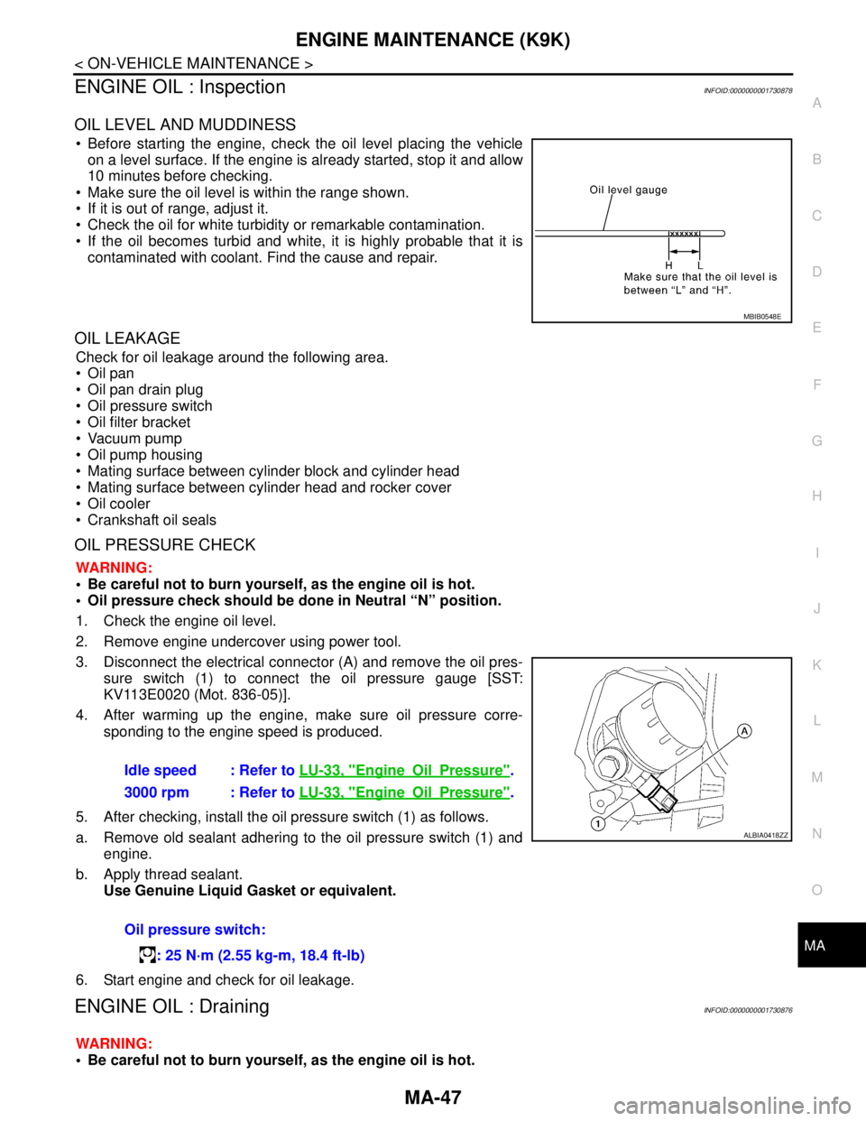
OIL LEVEL AND MUDDINESS
Before starting the engine, check the oil level placing the vehicle
on a level surface. If the engine is already started, stop it and allow
10 minutes before checking.
Make sure the oil level is within the range shown.
If it is out of range, adjust it.
Check the oil for white turbidity or remarkable contamination.
If the oil becomes turbid and white, it is highly probable that it is
contaminated with coolant. Find the cause and repair.
OIL LEAKAGE
Check for oil leakage around the following area.
Oil pan
Oil pan drain plug
Oil pressure switch
Oil filter bracket
Vacuum pump
Oil pump housing
Mating surface between cylinder block and cylinder head
Mating surface between cylinder head and rocker cover
Oil cooler
Crankshaft oil seals
OIL PRESSURE CHECK
WARNING:
Be careful not to burn yourself, as the engine oil is hot.
Oil pressure check should be done in Neutral “N” position.
1. Check the engine oil level.
2. Remove engine undercover using power tool.
3. Disconnect the electrical connector (A) and remove the oil pres-
sure switch (1) to connect the oil pressure gauge [SST:
KV113E0020 (Mot. 836-05)].
4. After warming up the engine, make sure oil pressure corre-
sponding to the engine speed is produced.
5. After checking, install the oil pressure switch (1) as follows.
a. Remove old sealant adhering to the oil pressure switch (1) and
engine.
b. Apply thread sealant.
Use Genuine Liquid Gasket or equivalent.
6. Start engine and check for oil leakage.
ENGINE OIL : DrainingINFOID:0000000001730876
WARNING:
Be careful not to burn yourself, as the engine oil is hot.
MBIB0548E
Idle speed : Refer to LU-33, "EngineOilPressure".
3000 rpm : Refer to LU-33, "
EngineOilPressure".
Oil pressure switch:
: 25 N·m (2.55 kg-m, 18.4 ft-lb)
ALBIA0418ZZ
Page 4288 of 5883
MA-48
< ON-VEHICLE MAINTENANCE >
ENGINE MAINTENANCE (K9K)
Prolonged and repeated contact with used engine oil may cause skin cancer: try to avoid direct skin
contact with used oil. If skin contact is made, wash thoroughly with soap or hand cleaner as soon as
possible.
1. Put the vehicle on a level surface.
2. Warm up engine, and check for oil leakage from engine components.
3. Stop engine and wait for 10 minutes.
4. Loosen oil filler cap.
5. Remove drain plug and then drain engine oil.
ENGINE OIL : RefillingINFOID:0000000001730877
1. Refill with new engine oil.
The refill capacity depends on the oil temperature and drain time.
Use these specifications for reference only.
Always use the dipstick to determine when the proper amount of oil
is in the engine.
CAUTION:
Be sure to clean drain plug and install with new washer.
The refill capacity depends on the oil temperature and drain
time. Use these specifications for reference only.
Always use the dipstick to determine when the proper amount of oil is in the engine.
2. Warm up engine and check area around drain plug and oil filter for oil leakage.
3. Stop engine and wait for 10 minutes.
4. Check oil level and add engine oil as necessary. Refer to LU-26, "
Inspection".
OIL FILTER
OIL FILTER : ReplacementINFOID:0000000001730879
1. Remove engine undercover using power tool.
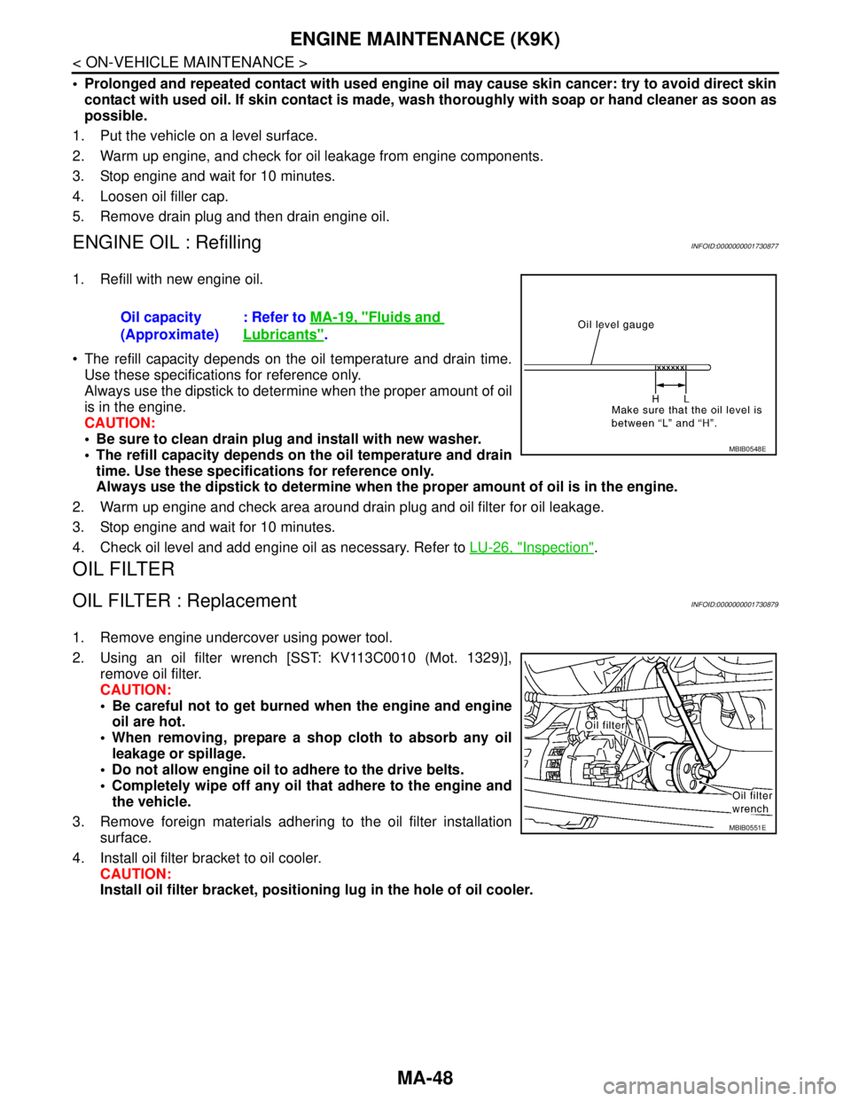
2. Using an oil filter wrench [SST: KV113C0010 (Mot. 1329)],
remove oil filter.
CAUTION:
Be careful not to get burned when the engine and engine
oil are hot.
When removing, prepare a shop cloth to absorb any oil
leakage or spillage.
Do not allow engine oil to adhere to the drive belts.
Completely wipe off any oil that adhere to the engine and
the vehicle.
3. Remove foreign materials adhering to the oil filter installation
surface.
4. Install oil filter bracket to oil cooler.
CAUTION:
Install oil filter bracket, positioning lug in the hole of oil cooler. Oil capacity
(Approximate): Refer to MA-19, "
Fluids and
Lubricants".
MBIB0548E
MBIB0551E
Page 4289 of 5883
ENGINE MAINTENANCE (K9K)
MA-49
< ON-VEHICLE MAINTENANCE >
C
D
E
F
G
H
I
J
K
L
MB
MAN
OA
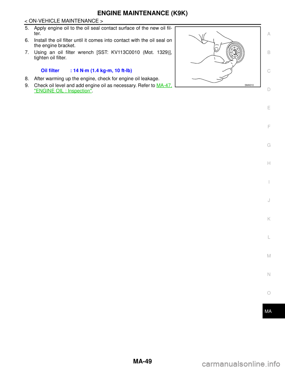
5. Apply engine oil to the oil seal contact surface of the new oil fil-
ter.
6. Install the oil filter until it comes into contact with the oil seal on
the engine bracket.
7. Using an oil filter wrench [SST: KV113C0010 (Mot. 1329)],
tighten oil filter.
8. After warming up the engine, check for engine oil leakage.
9. Check oil level and add engine oil as necessary. Refer to MA-47,
"ENGINE OIL : Inspection". Oil filter : 14 N·m (1.4 kg-m, 10 ft-lb)
SMA010
Page 4291 of 5883
CHASSIS AND BODY MAINTENANCE
MA-51
< ON-VEHICLE MAINTENANCE >
C
D
E
F
G
H
I
J
K
L
MB
MAN
OA
2. Remove filler plug (1) and check oil level at filler plug hole as
shown.
CAUTION:
Do not start engine while checking oil level
3. Install a new gasket onto filler plug (1) and install it into tran-
saxle. Tighten filler plug to specification. Refer to EM-166,
"Component" .
CAUTION:
Do not reuse gasket.
Changing M/T OilINFOID:0000000001730900
DRAINING
1. Start engine and let it run to warm up transaxle.
2. Stop engine. Remove drain plug (1) and drain oil.
3. Install a new gasket onto drain plug (1) and install it into tran-
saxle. Tighten drain plug to specification. Refer to TM-628,
"Exploded View" (RS5F91R) or TM-672, "Exploded View"
(RS6F94R).
CAUTION:
Do not reuse gasket.
FILLING
1. Remove filler plug (1). Fill with new oil until oil level reaches the
specified limit at filler plug hole as shown.
2. After refilling oil, check oil level. Install a new gasket on filler plug
(1), then install it into transaxle. Tighten filler plug to specifica-
tion. Refer to TM-628, "
Exploded View" (RS5F91R) or TM-672,
"Exploded View" (RS6F94R).
CAUTION:
Do not reuse gasket.
Checking A/T Fluid: RE4F03BINFOID:0000000001730901
1. Warm up engine.
2. Check for A/T fluid leakage.
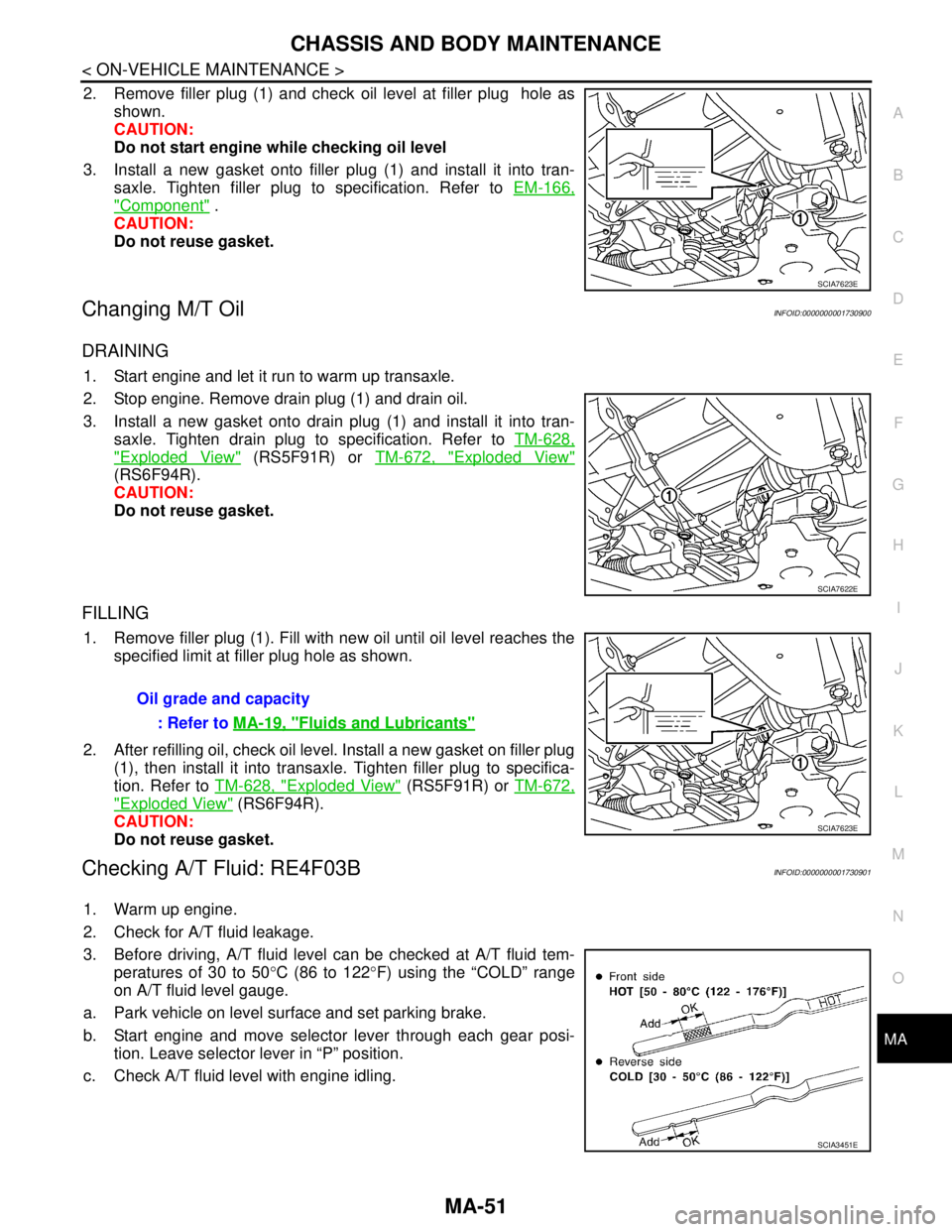
3. Before driving, A/T fluid level can be checked at A/T fluid tem-
peratures of 30 to 50°C (86 to 122°F) using the “COLD” range
on A/T fluid level gauge.
a. Park vehicle on level surface and set parking brake.
b. Start engine and move selector lever through each gear posi-
tion. Leave selector lever in “P” position.
c. Check A/T fluid level with engine idling.
SCIA7623E
SCIA7622E
Oil grade and capacity
: Refer to MA-19, "
Fluids and Lubricants"
SCIA7623E
SCIA3451E
Page 4293 of 5883
CHASSIS AND BODY MAINTENANCE
MA-53
< ON-VEHICLE MAINTENANCE >
C
D
E
F
G
H
I
J
K
L
MB
MAN
OA
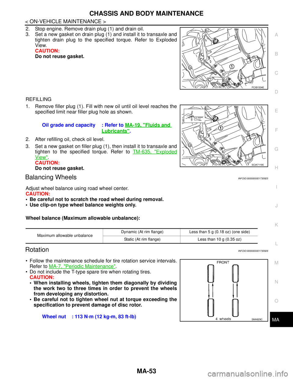
2. Stop engine. Remove drain plug (1) and drain oil.
3. Set a new gasket on drain plug (1) and install it to transaxle and
tighten drain plug to the specified torque. Refer to Exploded
View.
CAUTION:
Do not reuse gasket.
REFILLING
1. Remove filler plug (1). Fill with new oil until oil level reaches the
specified limit near filler plug hole as shown.
2. After refilling oil, check oil level.
3. Set a new gasket on filler plug (1), then install it to transaxle and
tighten to the specified torque. Refer to TM-635, "
Exploded
View".
CAUTION:
Do not reuse gasket.
Balancing WheelsINFOID:0000000001730925
Adjust wheel balance using road wheel center.
CAUTION:
Be careful not to scratch the road wheel during removal.
Use clip-on type wheel balance weights only.
Wheel balance (Maximum allowable unbalance):
RotationINFOID:0000000001730926
Follow the maintenance schedule for tire rotation service intervals.
Refer to MA-7, "
Periodic Maintenance".
Do not include the T-type spare tire when rotating tires.
CAUTION:
When installing wheels, tighten them diagonally by dividing
the work two to three times in order to prevent the wheels
from developing any distortion.
Be careful not to tighten wheel nut at torque exceeding the
specification to prevent damage of disc rotor.
PCIB1504E
Oil grade and capacity : Refer to MA-19, "Fluids and
Lubricants".
SCIA7119E
Maximum allowable unbalanceDynamic (At rim flange) Less than 5 g (0.18 oz) (one side)
Static (At rim flange) Less than 10 g (0.35 oz)
Wheel nut : 113 N·m (12 kg-m, 83 ft-lb)SMA829C
Page 4309 of 5883

MWI-2
IPDM E/R (INTELLIGENT POWER DISTRIBU-
TION MODULE ENGINE ROOM) : Diagnosis Pro-
cedure .....................................................................
27
FUEL LEVEL SENSOR SIGNAL CIRCUIT .......29
Description ..............................................................29
Component Function Check ...................................29
Diagnosis Procedure .............................................29
Component Inspection ............................................30
OIL PRESSURE SWITCH SIGNAL CIRCUIT ...31
Description ..............................................................31
Component Function Check ...................................31
Diagnosis Procedure ..............................................31
Component Inspection ............................................31
OIL LEVEL SENSOR SIGNAL CIRCUIT ..........32
Description ..............................................................32
Diagnosis Procedure (With Diesel) .........................32
Diagnosis Procedure (Without Diesel) ....................32
Component Inspection (With Diesel) ......................32
Component Inspection (Without Diesel) .................33
AMBIENT SENSOR SIGNAL CIRCUIT .............34
Description ..............................................................34
Diagnosis Procedure ..............................................34
Component Inspection ............................................35
ECU DIAGNOSIS ........................................36
COMBINATION METER ....................................36
Reference Value .....................................................36
Wiring Diagram .......................................................39
Fail Safe .................................................................53
DTC Index ..............................................................54
BCM (BODY CONTROL MODULE) ..................55
Reference Value .....................................................55
Terminal Layout ......................................................58
Physical Values ......................................................58
Wiring Diagram .......................................................70
DTC Inspection Priority Chart ..............................73
DTC Index ..............................................................74
IPDM E/R (INTELLIGENT POWER DISTRI-
BUTION MODULE ENGINE ROOM) .................
75
Reference Value .....................................................75
Terminal Layout ......................................................77
Physical Values ......................................................77
Wiring Diagram .......................................................81
Fail Safe .................................................................84
DTC Index ..............................................................86
SYMPTOM DIAGNOSIS ............................87
THE FUEL GAUGE POINTER DOES NOT
MOVE .................................................................
87
Description ..............................................................87
Diagnosis Procedure ...............................................87
THE FUEL GAUGE POINTER DOES NOT
MOVE TO "F" WHEN REFUELING ..................
88
Description ..............................................................88
Diagnosis Procedure ...............................................88
THE OIL PRESSURE WARNING LAMP
DOES NOT TURN ON .......................................
89
Description ..............................................................89
Diagnosis Procedure ...............................................89
THE OIL PRESSURE WARNING LAMP
DOES NOT TURN OFF .....................................
90
Description ..............................................................90
Diagnosis Procedure ...............................................90
THE AMBIENT TEMPERATURE DISPLAY IS
INCORRECT ......................................................
91
Description ..............................................................91
Diagnosis Procedure ...............................................91
NORMAL OPERATING CONDITION ................92
INFORMATION DISPLAY .........................................92
INFORMATION DISPLAY : Description ..................92
PRECAUTION ............................................93
PRECAUTIONS .................................................93
Supplemental Restraint System (SRS) "AIR BAG"
and "SEAT BELT PRE-TENSIONER" ....................
93
ON-VEHICLE REPAIR ...............................94
COMBINATION METER ....................................94
Removal and Installation .........................................94
DISASSEMBLY AND ASSEMBLY ............97
COMBINATION METER ....................................97
Disassembly and Assembly ....................................97
Page 4313 of 5883
MWI-6
< FUNCTION DIAGNOSIS >
METER SYSTEM
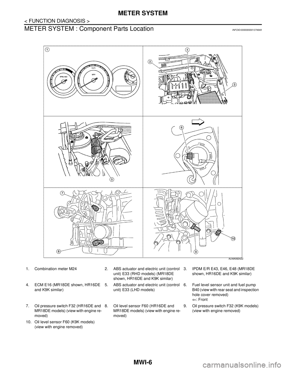
METER SYSTEM : Component Parts Location
INFOID:0000000001374649
1. Combination meter M24 2. ABS actuator and electric unit (control
unit) E33 (RHD models) (MR18DE
shown, HR16DE and K9K similar)3. IPDM E/R E43, E46, E48 (MR18DE
shown, HR16DE and K9K similar)
4. ECM E16 (MR18DE shown, HR16DE
and K9K similar)5. ABS actuator and electric unit (control
unit) E33 (LHD models)6. Fuel level sensor unit and fuel pump
B40 (view with rear seat and inspection
hole cover removed)
⇐: Front
7. Oil pressure switch F32 (HR16DE and
MR18DE models) (view with engine re-
moved)8. Oil level sensor F60 (HR16DE and
MR18DE models) (view with engine re-
moved)9. Oil pressure switch F32 (K9K models)
(view with engine removed)
10. Oil level sensor F60 (K9K models)
(view with engine removed)
ALNIA0624ZZ
Page 4314 of 5883
MWI
METER SYSTEM
MWI-7
< FUNCTION DIAGNOSIS >
C
D
E
F
G
H
I
J
K
L
MB A
O
P
METER SYSTEM : Component DescriptionINFOID:0000000001537306
SPEEDOMETER
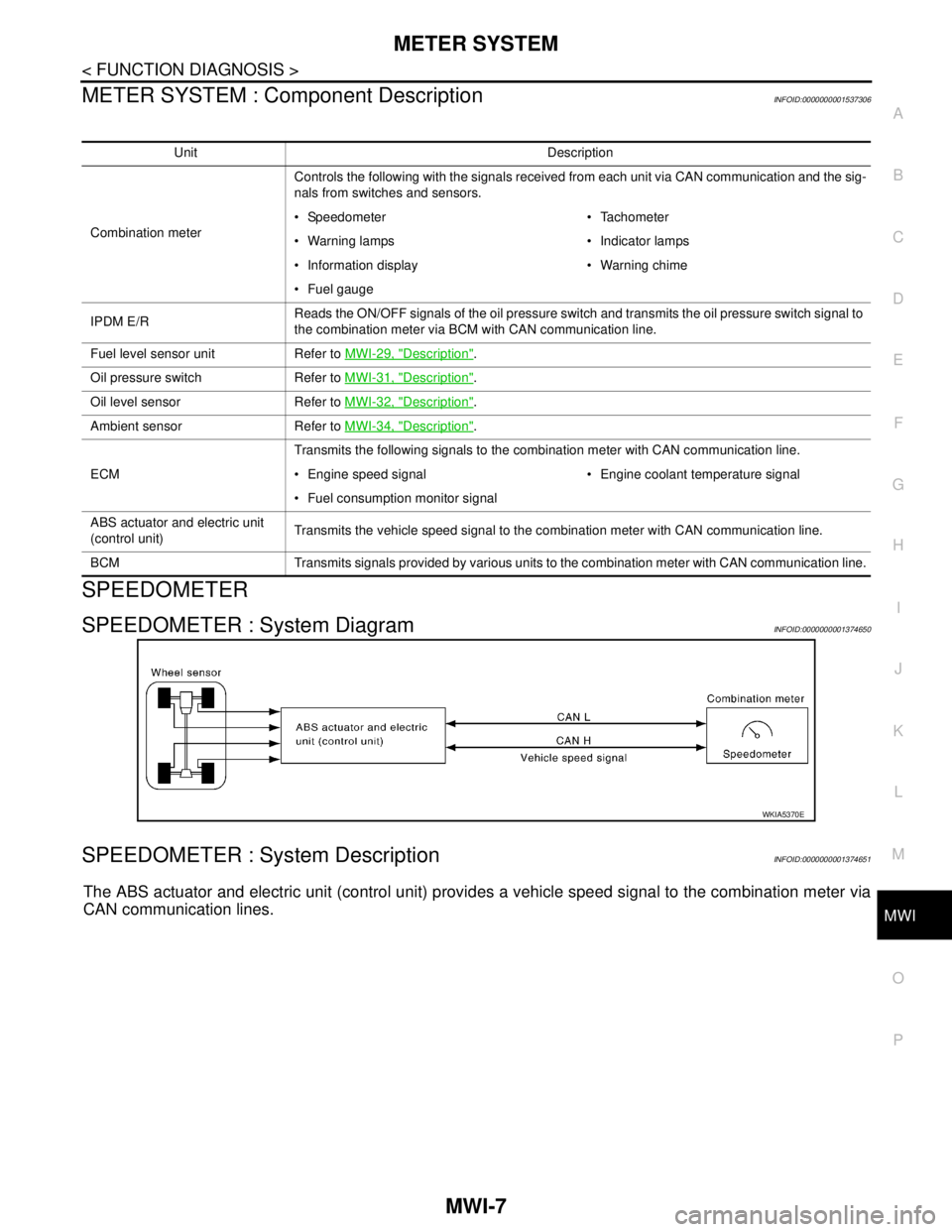
SPEEDOMETER : System DiagramINFOID:0000000001374650
SPEEDOMETER : System DescriptionINFOID:0000000001374651
The ABS actuator and electric unit (control unit) provides a vehicle speed signal to the combination meter via
CAN communication lines.
Unit Description
Combination meterControls the following with the signals received from each unit via CAN communication and the sig-
nals from switches and sensors.
Speedometer Tachometer
Warning lamps Indicator lamps
Information display Warning chime
Fuel gauge
IPDM E/RReads the ON/OFF signals of the oil pressure switch and transmits the oil pressure switch signal to
the combination meter via BCM with CAN communication line.
Fuel level sensor unit Refer to MWI-29, "
Description".
Oil pressure switch Refer to MWI-31, "
Description".
Oil level sensor Refer to MWI-32, "
Description".
Ambient sensor Refer to MWI-34, "
Description".
ECMTransmits the following signals to the combination meter with CAN communication line.
Engine speed signal Engine coolant temperature signal
Fuel consumption monitor signal
ABS actuator and electric unit
(control unit)Transmits the vehicle speed signal to the combination meter with CAN communication line.
BCM Transmits signals provided by various units to the combination meter with CAN communication line.
WKIA5370E