2007 NISSAN TIIDA brake
[x] Cancel search: brakePage 4330 of 5883

MWI
DIAGNOSIS SYSTEM (METER)
MWI-23
< FUNCTION DIAGNOSIS >
C
D
E
F
G
H
I
J
K
L
MB A
O
P
NOTE:
Some items are not available due to vehicle specification.
*: The monitor will indicate “OFF” even though the brake warning lamp is on if either of the following conditions exist.
The parking brake is engaged
The brake fluid level is lowDOOR W/L [ON/OFF] X Displays [ON/OFF] condition of door warning lamp.
HI-BEAM IND [ON/OFF] X Displays [ON/OFF] condition of high beam indicator.
TURN IND [ON/OFF] X Displays [ON/OFF] condition of turn indicator.
FR FOG IND X Displays [ON/OFF] condition of front fog lamp indicator.
RR FOG IND X Displays [ON/OFF] condition of rear fog lamp indicator.
OIL W/L [ON/OFF] X Displays [ON/OFF] condition of oil pressure warning lamp.
LIGHT IND X Displays [ON/OFF] condition of exterior lamp indicator.
VDC/TCS IND [ON/OFF] X Displays [ON/OFF] condition of VDC OFF indicator lamp.
ABS W/L [ON/OFF] X Displays [ON/OFF] condition of ABS warning lamp.
SLIP IND [ON/OFF] X Displays [ON/OFF] condition of SLIP indicator lamp.
BRAKE W/L [ON/OFF] X Displays [ON/OFF] condition of brake warning lamp.*
OIL LEVEL IND X Displays [ON/OFF] condition of oil level indicator.
KEY G W/L [ON/OFF] X Displays [ON/OFF] condition of key green warning lamp.
KEY R W/L [ON/OFF] X Displays [ON/OFF] condition of key red warning lamp.
KEY KNOB W/L [ON/OFF] X Displays [ON/OFF] condition of key knob warning lamp.
PNP P SW X X Displays [ON/OFF] condition of inhibitor P switch.
PNP N SW X X Displays [ON/OFF] condition of inhibitor N switch.
O/D OFF SW X Displays [ON/OFF] condition of O/D OFF switch.
BRAKE SW [ON/OFF] X Displays [ON/OFF] condition of parking brake switch.
P RANGE IND [ON/OFF] X X Displays [ON/OFF] condition of A/T shift P range indicator.
R RANGE IND [ON/OFF] X X Displays [ON/OFF] condition of A/T shift R range indicator.
N RANGE IND [ON/OFF] X X Displays [ON/OFF] condition of A/T shift N range indicator.
D RANGE IND [ON/OFF] X X Displays [ON/OFF] condition of A/T shift D range indicator.
2 RANGE IND [ON/OFF] X X Displays [ON/OFF] condition of A/T shift 2 range indicator.
1 RANGE IND [ON/OFF] X X Displays [ON/OFF] condition of A/T shift 1range indicator.
O/D OFF W/L X Displays [ON/OFF] condition of O/D OFF indicator lamp.
CRUISE IND [ON/OFF] X Displays [ON/OFF] condition of CRUISE indicator.
EPS W/L X Displays [ON/OFF] condition of EPS warning lamp. Display item [Unit]MAIN
SIGNALSSELECTION
FROM MENUDescription
Page 4343 of 5883
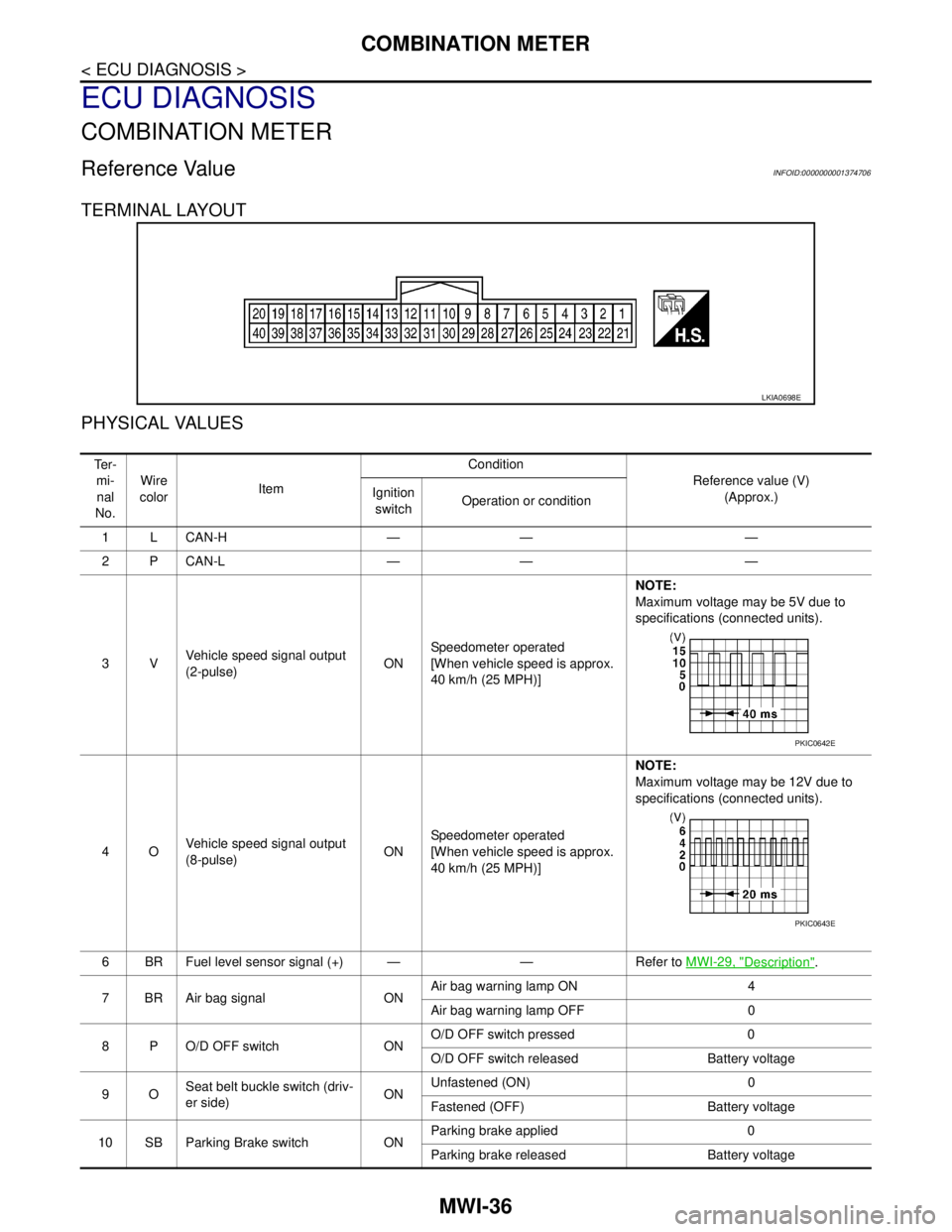
MWI-36
< ECU DIAGNOSIS >
COMBINATION METER
ECU DIAGNOSIS
COMBINATION METER
Reference ValueINFOID:0000000001374706
TERMINAL LAYOUT
PHYSICAL VALUES
LKIA0698E
Te r -
mi-
nal
No.Wire
colorItemCondition
Reference value (V)
(Approx.) Ignition
switchOperation or condition
1LCAN-H — — —
2PCAN-L — — —
3VVehicle speed signal output
(2-pulse)ONSpeedometer operated
[When vehicle speed is approx.
40 km/h (25 MPH)] NOTE:
Maximum voltage may be 5V due to
specifications (connected units).
4OVehicle speed signal output
(8-pulse)ONSpeedometer operated
[When vehicle speed is approx.
40 km/h (25 MPH)]NOTE:
Maximum voltage may be 12V due to
specifications (connected units).
6 BR Fuel level sensor signal (+) — — Refer to MWI-29, "
Description".
7 BR Air bag signal ONAir bag warning lamp ON 4
Air bag warning lamp OFF 0
8 P O/D OFF switch ONO/D OFF switch pressed 0
O/D OFF switch released Battery voltage
9OSeat belt buckle switch (driv-
er side)ONUnfastened (ON) 0
Fastened (OFF) Battery voltage
10 SB Parking Brake switch ONParking brake applied 0
Parking brake released Battery voltage
PKIC0642E
PKIC0643E
Page 4344 of 5883
MWI
COMBINATION METER
MWI-37
< ECU DIAGNOSIS >
C
D
E
F
G
H
I
J
K
L
MB A
O
P
11 LG Brake fluid level switch ONBrake fluid level low 0
Brake fluid level normal Battery voltage
16 VSteering switch (trip comput-
er) signalONPress the steering switch (trip
computer)0
Other than the above 5
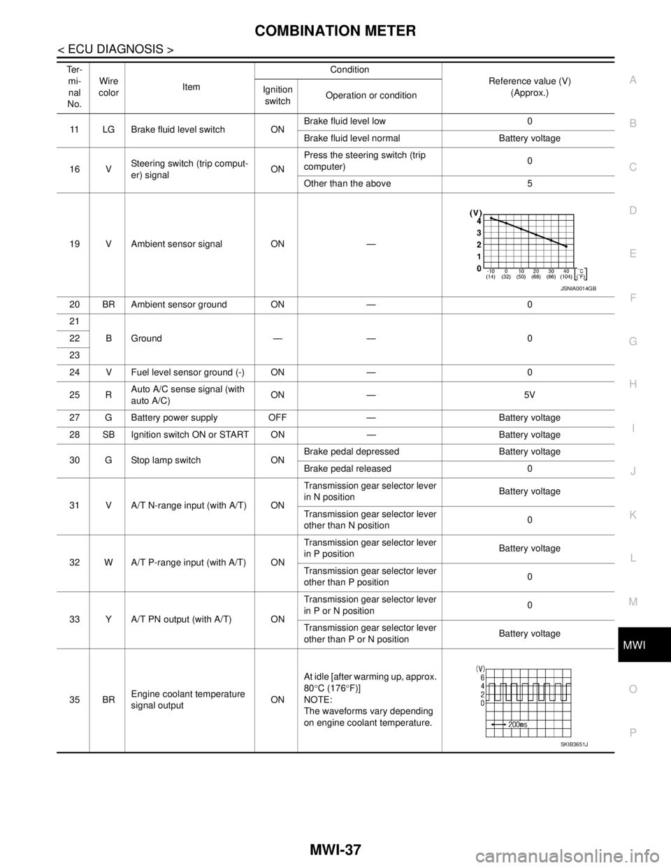
19 V Ambient sensor signal ON —
20 BR Ambient sensor ground ON — 0
21
BGround — — 0 22
23
24 V Fuel level sensor ground (-) ON — 0
25 RAuto A/C sense signal (with
auto A/C)ON — 5V
27 G Battery power supply OFF — Battery voltage
28 SB Ignition switch ON or START ON — Battery voltage
30 G Stop lamp switch ONBrake pedal depressed Battery voltage
Brake pedal released 0
31 V A/T N-range input (with A/T) ONTransmission gear selector lever
in N positionBattery voltage
Transmission gear selector lever
other than N position0
32 W A/T P-range input (with A/T) ONTransmission gear selector lever
in P positionBattery voltage
Transmission gear selector lever
other than P position0
33 Y A/T PN output (with A/T) ONTransmission gear selector lever
in P or N position0
Transmission gear selector lever
other than P or N positionBattery voltage
35 BREngine coolant temperature
signal outputONAt idle [after warming up, approx.
80°C (176°F)]
NOTE:
The waveforms vary depending
on engine coolant temperature. Te r -
mi-
nal
No.Wire
colorItemCondition
Reference value (V)
(Approx.) Ignition
switchOperation or condition
JSNIA0014GB
SKIB3651J
Page 4361 of 5883

MWI-54
< ECU DIAGNOSIS >
COMBINATION METER
DTC Index
INFOID:0000000001374709
NOTE:
“TIME” indicates the following.
0: Indicates that a malfunction is detected at present.
1-63: Indicates that a malfunction was detected in the past. (Displays number of ignition switch OFF → ON
cycles after malfunction is detected. Self-diagnosis result is erased when “63” is exceeded.)
Function Specifications
Speedometer
Zero indication. Tachometer
Fuel gauge
Illumination control Meter illumination Change to nighttime mode when communication is lost.
Segment LCD Odometer Freeze current indication.
Buzzer Buzzer turns off.
Warning lamp/indicator lampABS warning lamp
Lamp turns on when communication is lost. Brake warning lamp
ESP OFF indicator lamp
SLIP indicator lamp
Side and headlight indicator
Lamp turns off when communication is lost. Low water temperature indicator lamp
High water temperature warning lamp
Malfunction indicator
Power steering warning lamp
Air bag warning lamp
High beam indicator
Turn signal indicator lamp
Intelligent Key system warning lamp
CRUISE indicator lamp
Oil pressure warning lamp
Door warning lamp
Front fog lamp indicator
Rear fog lamp indicator
O/D OFF indicator lamp
Lamp turns off when disconnected. Charge warning lamp
Driver and passenger seat belt warn-
ing lamp
CONSULT-III display MalfunctionReference
page
CAN COMM CIRC
[U1000]Malfunction is detected in CAN communication.
CAUTION:
Even when there is no malfunction on CAN communication system, malfunction may be
misinterpreted when battery has low voltage (when maintaining 7 - 8 V for about 2 sec-
onds) or 10A fuse [No. 19, located in the fuse block (J/B)] is disconnected.MWI-24
VEHICLE SPEED
CIRC
[B2205]Malfunction is detected when an erroneous speed signal is input.
CAUTION:
Even when there is no malfunction on speed signal system, malfunction may be misin-
terpreted when battery has low voltage (when maintaining 7 - 8 V for about 2 seconds). MWI-25
Page 4370 of 5883
MWI
BCM (BODY CONTROL MODULE)
MWI-63
< ECU DIAGNOSIS >
C
D
E
F
G
H
I
J
K
L
MB A
O
P
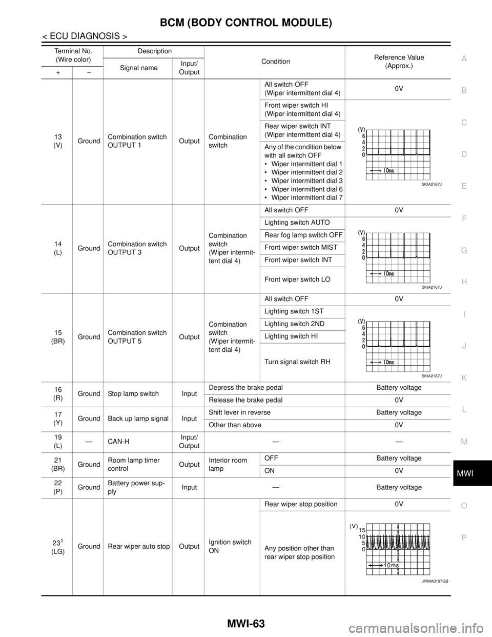
13
(V)GroundCombination switch
OUTPUT 1OutputCombination
switchAll switch OFF
(Wiper intermittent dial 4)0V
Front wiper switch HI
(Wiper intermittent dial 4)
Rear wiper switch INT
(Wiper intermittent dial 4)
Any of the condition below
with all switch OFF
Wiper intermittent dial 1
Wiper intermittent dial 2
Wiper intermittent dial 3
Wiper intermittent dial 6
Wiper intermittent dial 7
14
(L)GroundCombination switch
OUTPUT 3OutputCombination
switch
(Wiper intermit-
tent dial 4)All switch OFF 0V
Lighting switch AUTO
Rear fog lamp switch OFF
Front wiper switch MIST
Front wiper switch INT
Front wiper switch LO
15
(BR)GroundCombination switch
OUTPUT 5OutputCombination
switch
(Wiper intermit-
tent dial 4)All switch OFF 0V
Lighting switch 1ST
Lighting switch 2ND
Lighting switch HI
Turn signal switch RH
16
(R)Ground Stop lamp switch InputDepress the brake pedal Battery voltage
Release the brake pedal 0V
17
(Y)Ground Back up lamp signal InputShift lever in reverse Battery voltage
Other than above 0V
19
(L)—CAN-HInput/
Output——
21
(BR)GroundRoom lamp timer
controlOutputInterior room
lampOFF Battery voltage
ON 0V
22
(P)GroundBattery power sup-
plyInput — Battery voltage
23
1
(LG)Ground Rear wiper auto stop OutputIgnition switch
ONRear wiper stop position 0V
Any position other than
rear wiper stop position Terminal No.
(Wire color)Description
ConditionReference Value
(Approx.)
Signal nameInput/
Output +−
SKIA2167J
SKIA2167J
SKIA2167J
JPMIA0197GB
Page 4405 of 5883

PB-1
BRAKES
C
D
E
G
H
I
J
K
L
M
SECTION PB
A
B
PB
N
O
P
CONTENTS
PARKING BRAKE SYSTEM
PRECAUTION ...............................................2
PRECAUTIONS ...................................................2
Precaution for Supplemental Restraint System
(SRS) "AIR BAG" and "SEAT BELT PRE-TEN-
SIONER" ...................................................................
2
PREPARATION ............................................3
PREPARATION ...................................................3
Commercial Service Tool ..........................................3
ON-VEHICLE MAINTENANCE .....................4
PARKING BRAKE CONTROL ............................4
On-Vehicle Service ...................................................4
REMOVAL AND INSTALLATION ................5
PARKING BRAKE CONTROL ...........................5
Component ...............................................................5
Removal and Installation ..........................................5
PARKING BRAKE SHOE ..................................7
Exploded View ..........................................................7
Removal and Installation ..........................................7
Drum and Lining Break-in .........................................9
SERVICE DATA AND SPECIFICATIONS
(SDS) ............................................................
10
SERVICE DATA AND SPECIFICATIONS
(SDS) .................................................................
10
Parking Brake Control .............................................10
Parking Drum Brake ................................................10
Page 4408 of 5883
PB-4
< ON-VEHICLE MAINTENANCE >
PARKING BRAKE CONTROL
ON-VEHICLE MAINTENANCE
PARKING BRAKE CONTROL
On-Vehicle ServiceINFOID:0000000001716774
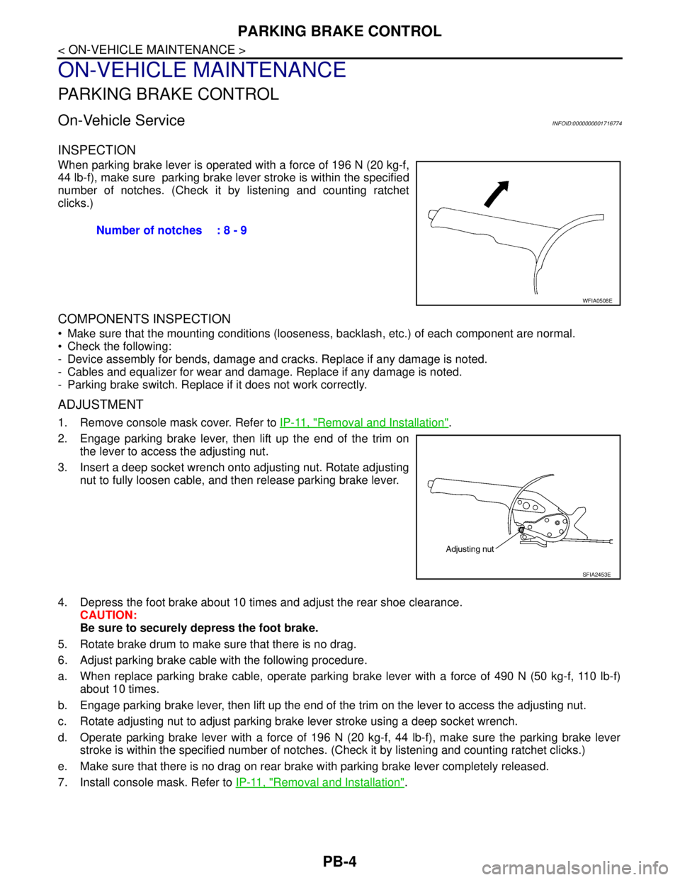
INSPECTION
When parking brake lever is operated with a force of 196 N (20 kg-f,
44 lb-f), make sure parking brake lever stroke is within the specified
number of notches. (Check it by listening and counting ratchet
clicks.)
COMPONENTS INSPECTION
Make sure that the mounting conditions (looseness, backlash, etc.) of each component are normal.
Check the following:
- Device assembly for bends, damage and cracks. Replace if any damage is noted.
- Cables and equalizer for wear and damage. Replace if any damage is noted.
- Parking brake switch. Replace if it does not work correctly.
ADJUSTMENT
1. Remove console mask cover. Refer to IP-11, "Removal and Installation".
2. Engage parking brake lever, then lift up the end of the trim on
the lever to access the adjusting nut.
3. Insert a deep socket wrench onto adjusting nut. Rotate adjusting
nut to fully loosen cable, and then release parking brake lever.
4. Depress the foot brake about 10 times and adjust the rear shoe clearance.
CAUTION:
Be sure to securely depress the foot brake.
5. Rotate brake drum to make sure that there is no drag.
6. Adjust parking brake cable with the following procedure.
a. When replace parking brake cable, operate parking brake lever with a force of 490 N (50 kg-f, 110 lb-f)
about 10 times.
b. Engage parking brake lever, then lift up the end of the trim on the lever to access the adjusting nut.
c. Rotate adjusting nut to adjust parking brake lever stroke using a deep socket wrench.
d. Operate parking brake lever with a force of 196 N (20 kg-f, 44 lb-f), make sure the parking brake lever
stroke is within the specified number of notches. (Check it by listening and counting ratchet clicks.)
e. Make sure that there is no drag on rear brake with parking brake lever completely released.
7. Install console mask. Refer to IP-11, "
Removal and Installation". Number of notches : 8 - 9
WFIA0508E
SFIA2453E
Page 4409 of 5883
PARKING BRAKE CONTROL
PB-5
< REMOVAL AND INSTALLATION >
C
D
E
G
H
I
J
K
L
MA
B
PB
N
O
P
REMOVAL AND INSTALLATION
PARKING BRAKE CONTROL
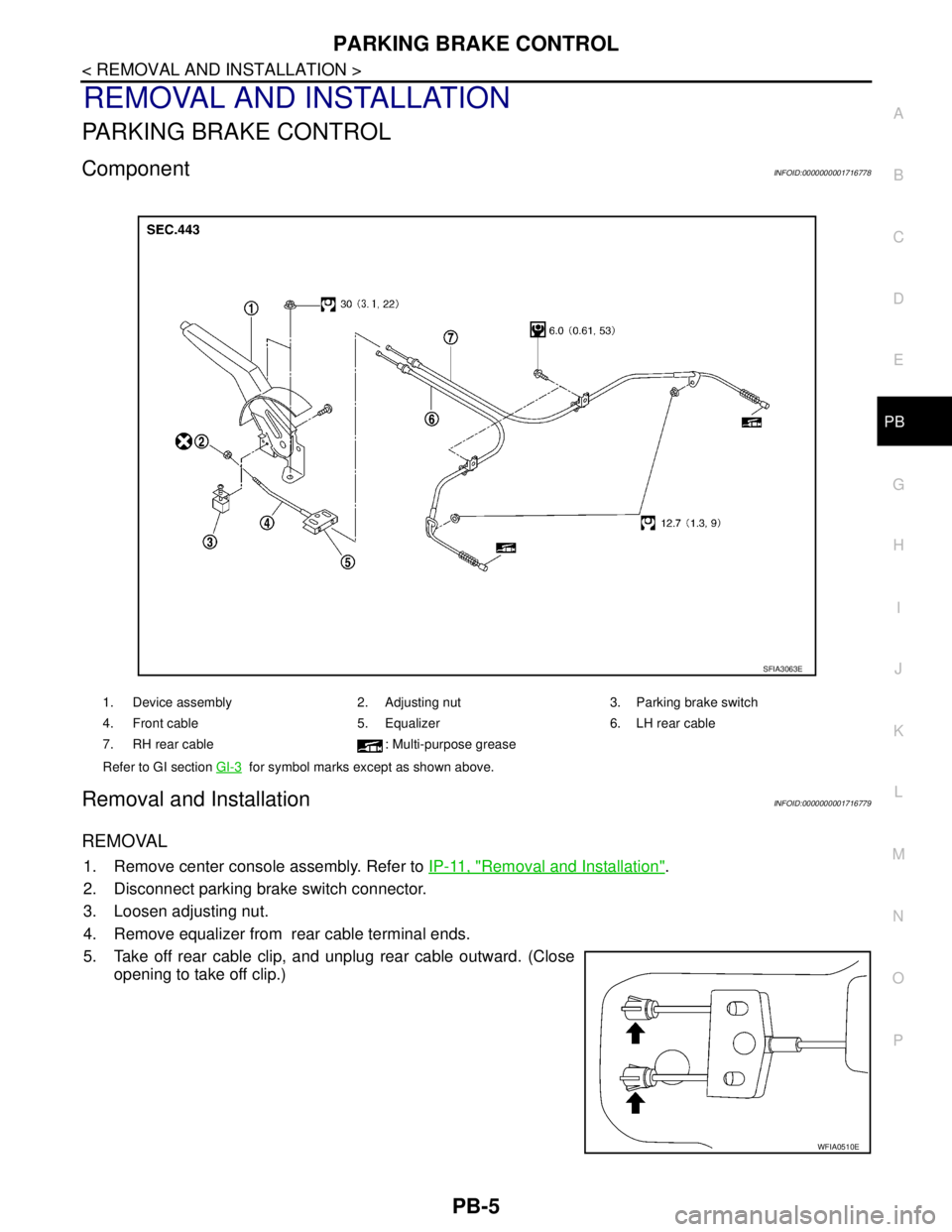
ComponentINFOID:0000000001716778
Removal and InstallationINFOID:0000000001716779
REMOVAL
1. Remove center console assembly. Refer to IP-11, "Removal and Installation".
2. Disconnect parking brake switch connector.
3. Loosen adjusting nut.
4. Remove equalizer from rear cable terminal ends.
5. Take off rear cable clip, and unplug rear cable outward. (Close
opening to take off clip.)
1. Device assembly 2. Adjusting nut 3. Parking brake switch
4. Front cable 5. Equalizer 6. LH rear cable
7. RH rear cable : Multi-purpose grease
Refer to GI section GI-3
for symbol marks except as shown above.
SFIA3063E
WFIA0510E