Page 3019 of 5883
EXL-18
< FUNCTION DIAGNOSIS >
DAYTIME LIGHT SYSTEM
Component Description
INFOID:0000000001527657
Part Description
BCM Monitors lighting switch position, engine running status and parking brake status to
determine if conditions are set for daytime light system operation.
Requests the IPDM E/R via CAN communication lines to ground the daytime light
relay coil.
IPDM E/RControls ground to the daytime light relay coil based on requests from the BCM (via
CAN communication lines).
Combination switch
(Lighting & turn signal switch)Refer to XX-XX, "*****"
.
Combination meterMonitors engine running status and forwards that information to the BCM via CAN
communication lines.
Page 3075 of 5883

EXL-74
< SYMPTOM DIAGNOSIS >
EXTERIOR LIGHTING SYSTEM SYMPTOMS
Daytime light system does not activate. Either high beam bulb
Parking brake switch
Combination switch
BCM
IPDM E/R
Daytime light relay
Harness between IPDM E/R
and daytime light relay.Daytime light system description.
Refer to XX-XX, "*****"
.
Front fog lamp is not
turned ON.One side Front fog lamp bulb
Harness between IPDM E/R
and the front combination lamp
Front combination lamp
IPDM E/RFront fog lamp circuit
Refer to EXL-41
.
Both sideSymptom diagnosis
"BOTH SIDE FRONT FOG LAMPS ARE NOT TURNED ON"
Refer to EXL-79
.
Parking lamp is not turned
ON.One sideFuse
Parking lamp bulb
Harness between IPDM E/R
and the front/rear combination
lamp
Front/rear combination lamp
IPDM E/RParking lamp circuit
Refer to EXL-46
.
Both sidesSymptom diagnosis
"PARKING, LICENSE PLATE AND TAIL LAMPS ARE NOT TURNED
ON"
Refer to EXL-78
.
Turn signal lamp does not
blink.Indicator lamp is nor-
mal.
(The applicable side
performs the high flash-
er activation). Harness between BCM and
each turn signal lamp
Turn signal lamp bulb
Door mirror (if equipped with
turn signals in the door mirrors)Turn signal lamp circuit
Refer to EXL-52
.
Turn signal indicator lamp
does not blink.One side Combination meter —
Both sides
(Always) Turn signal indicator lamp sig-
nal
Combination meter
BCM Combination meter.
Data monitor "TURN IND"
BCM (FLASHER)
Active test "FLASHER"
Both sides
(Does blink when acti-
vating the hazard warn-
ing lamp with the
ignition switch OFF) The combination meter power
supply and the ground circuit
Combination meterCombination meter
Power supply and the ground circuit
Refer to XX-XX, "*****"
. Symptom Possible cause Inspection item
Page 3138 of 5883

FAX-4
< SYMPTOM DIAGNOSIS >
NOISE, VIBRATION AND HARSHNESS (NVH) TROUBLESHOOTING
SYMPTOM DIAGNOSIS
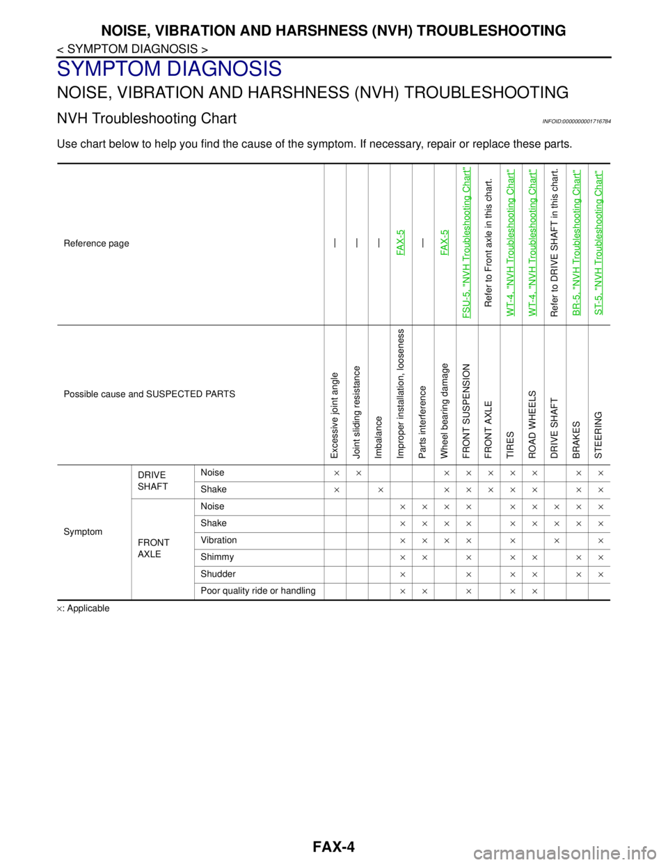
NOISE, VIBRATION AND HARSHNESS (NVH) TROUBLESHOOTING
NVH Troubleshooting ChartINFOID:0000000001716784
Use chart below to help you find the cause of the symptom. If necessary, repair or replace these parts.
×: ApplicableReference page
—
—
—
FA X - 5—
FA X - 5
FSU-5, "
NVH Troubleshooting Chart
"
Refer to Front axle in this chart.
WT-4, "
NVH Troubleshooting Chart
"
WT-4, "
NVH Troubleshooting Chart
"
Refer to DRIVE SHAFT in this chart.
BR-5, "
NVH Troubleshooting Chart
"
ST-5, "
NVH Troubleshooting Chart
"
Possible cause and SUSPECTED PARTS
Excessive joint angle
Joint sliding resistance
Imbalance
Improper installation, looseness
Parts interference
Wheel bearing damage
FRONT SUSPENSION
FRONT AXLE
TIRES
ROAD WHEELS
DRIVE SHAFT
BRAKES
STEERING
SymptomDRIVE
SHAFTNoise×× ××××× ××
Shake× × ××××× ××
FRONT
AXLENoise×××× ×××××
Shake×××× ×××××
Vibration×××××××
Shimmy×××××××
Shudder× × ×× ××
Poor quality ride or handling×××××
Page 3141 of 5883
FRONT WHEEL HUB AND KNUCKLE
FAX-7
< REMOVAL AND INSTALLATION >
C
E
F
G
H
I
J
K
L
MA
B
FA X
N
O
P
REMOVAL AND INSTALLATION
FRONT WHEEL HUB AND KNUCKLE
Removal and InstallationINFOID:0000000001716789
COMPONENT
REMOVAL
1. Remove wheel and tire using power tool. Refer to WT-6, "Rotation" .
2. Without disassembling the hydraulic lines, remove the torque member bolts using power tool. Then repo-
sition the torque member and brake caliper assembly aside with wire. Refer to BR-25, "
Removal and
Installation of Brake Caliper Assembly" .
CAUTION:
Do not depress brake pedal while brake caliper is removed.
3. Put alignment marks on disc rotor and wheel hub and bearing
assembly, then remove disc rotor.
4. Remove wheel sensor from steering knuckle. Refer to BRC-182, "
Removal and Installation" .
CAUTION:
Do not pull on wheel sensor harness.
1. Drive shaft 2. Steering knuckle 3. Splash guard
4. Wheel hub and bearing assembly 5. Cotter pin
WDIA0366E
SDIA1480E
Page 3143 of 5883
FRONT WHEEL HUB AND KNUCKLE
FAX-9
< REMOVAL AND INSTALLATION >
C
E
F
G
H
I
J
K
L
MA
B
FA X
N
O
P
Installation is the reverse order of removal. Note the following:
Perform the final tightening of each of parts under unladen conditions, which were removed when removing
wheel hub and bearing assembly and steering knuckle. Check the wheel alignment. Refer to FSU-6, "
Wheel
Alignment Inspection" .
When installing disc rotor on wheel hub and bearing assembly,
align the marks.
(When not using the alignment mark, refer to BR-34, "
Disassembly
and Assembly of Brake Caliper Assembly" .)
SDIA1480E
Page 3173 of 5883

FUEL TANK
FL-13
< ON-VEHICLE REPAIR >
C
D
E
F
G
H
I
J
K
L
MA
FL
N
P O
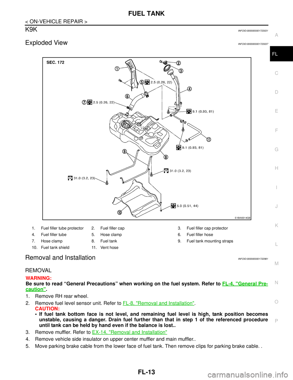
K9KINFOID:0000000001723031
Exploded ViewINFOID:0000000001723037
Removal and InstallationINFOID:0000000001722981
REMOVAL
WARNING:
Be sure to read “General Precautions” when working on the fuel system. Refer to FL-4, "
General Pre-
caution".
1. Remove RH rear wheel.
2. Remove fuel level sensor unit. Refer to FL-8, "
Removal and Installation".
CAUTION:
If fuel tank bottom face is not level, and remaining fuel level is high, tank position becomes
unstable, causing a danger. Drain fuel further than that in step 1 of the referenced procedure
until tank can be held by hand even if the balance is lost..
3. Remove muffler. Refer to EX-14, "
Removal and Installation"
4. Remove vehicle side insulator on upper center muffler and main muffler..
5. Move parking brake cable from the lower face of fuel tank. Then remove clips for parking brake cable. .
1. Fuel filler tube protector 2. Fuel filler cap 3. Fuel filler cap protector
4. Fuel filler tube 5. Hose clamp 6. Fuel filler hose
7. Hose clamp 8. Fuel tank 9. Fuel tank mounting straps
10. Fuel tank shield 11. Vent hose
E1BIA0014GB
Page 3175 of 5883

FUEL TANK
FL-15
< ON-VEHICLE REPAIR >
C
D
E
F
G
H
I
J
K
L
MA
FL
N
P O
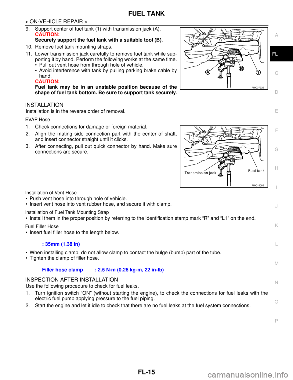
9. Support center of fuel tank (1) with transmission jack (A).
CAUTION:
Securely support the fuel tank with a suitable tool (B).
10. Remove fuel tank mounting straps.
11. Lower transmission jack carefully to remove fuel tank while sup-
porting it by hand. Perform the following works at the same time.
Pull out vent hose from through hole of vehicle.
Avoid interference with tank by pulling parking brake cable by
hand.
CAUTION:
Fuel tank may be in an unstable position because of the
shape of fuel tank bottom. Be sure to support tank securely.
INSTALLATION
Installation is in the reverse order of removal.
EVAP Hose
1. Check connections for damage or foreign material.
2. Align the mating side connection part with the center of shaft,
and insert connector straight until it clicks.
3. After connecting, pull out quick connector by hand. Make sure
connections are secure.
Installation of Vent Hose
Push vent hose into through hole of vehicle.
Insert vent hose into vent rubber hose, and secure it with clamp.
Installation of Fuel Tank Mounting Strap
Install them in the proper position by referring to the identification stamp mark “R” and “L1” on the end.
Fuel Filler Hose
Insert fuel filler hose to the length below.
When installing clamp, do not allow clamp to contact the bulge (bump) part of the tube.
Tighten the clamp of filler hose.
INSPECTION AFTER INSTALLATION
Use the following procedure to check for fuel leaks.
1. Turn ignition switch “ON” (without starting the engine), to check the connections for fuel leaks with the
electric fuel pump applying pressure to the fuel piping.
2. Start the engine and let it idle to check that there are no fuel leaks at the fuel system connections.
PBIC3792E
PBIC1508E
: 35mm (1.38 in)
Filler hose clamp : 2.5 N·m (0.26 kg-m, 22 in-lb)
Page 3181 of 5883

NOISE, VIBRATION AND HARSHNESS (NVH) TROUBLESHOOTING
FSU-5
< SYMPTOM DIAGNOSIS >
C
D
F
G
H
I
J
K
L
MA
B
FSU
N
O
P
SYMPTOM DIAGNOSIS
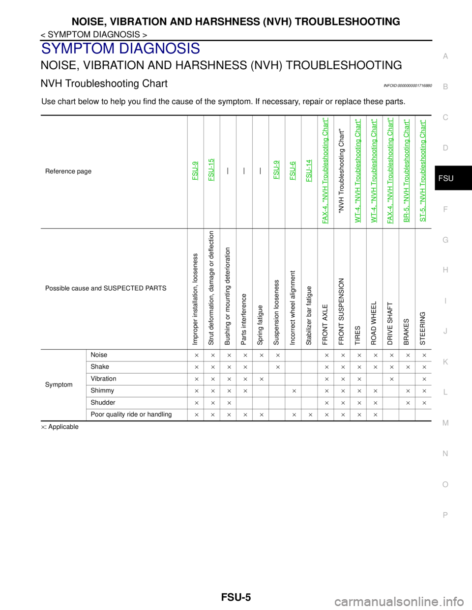
NOISE, VIBRATION AND HARSHNESS (NVH) TROUBLESHOOTING
NVH Troubleshooting ChartINFOID:0000000001716880
Use chart below to help you find the cause of the symptom. If necessary, repair or replace these parts.
×: ApplicableReference page
FSU-9 FSU-15
—
—
—
FSU-9FSU-6FSU-14
FAX-4, "
NVH Troubleshooting Chart
"
"NVH Troubleshooting Chart"
WT-4, "
NVH Troubleshooting Chart
"
WT-4, "
NVH Troubleshooting Chart
"
FAX-4, "
NVH Troubleshooting Chart
"
BR-5, "
NVH Troubleshooting Chart
"
ST-5, "
NVH Troubleshooting Chart
"
Possible cause and SUSPECTED PARTS
Improper installation, looseness
Strut deformation, damage or deflection
Bushing or mounting deterioration
Parts interference
Spring fatigue
Suspension looseness
Incorrect wheel alignment
Stabilizer bar fatigue
FRONT AXLE
FRONT SUSPENSION
TIRES
ROAD WHEEL
DRIVE SHAFT
BRAKES
STEERING
SymptomNoise×××××× ×××××××
Shake×××× × ×××××××
Vibration××××× ××× × ×
Shimmy×××× × ×××× ××
Shudder××× ×××× ××
Poor quality ride or handling××××× ××××××