Page 4750 of 5883

SPIRAL CABLE
SR-7
< ON-VEHICLE REPAIR >
C
D
E
F
G
I
J
K
L
MA
B
SR
N
O
P
SPIRAL CABLE
Removal and InstallationINFOID:0000000001404300
REMOVAL
WARNING:
When servicing the SRS, do not work from directly in front of air bag module.
CAUTION:
Before servicing the SRS, turn ignition switch OFF, disconnect both battery cables and wait at least
3 minutes.
Do not tap or bump the steering wheel.
Do not disassemble the spiral cable.
Do not allow oil, grease or water to come in contact with the spiral cable.
Replace the spiral cable if it has been dropped or sustained an impact.
With the steering linkage disconnected, the spiral cable may snap by turning the steering wheel
beyond the limited number of turns. The spiral cable can be turned counterclockwise about 2.5 turns
from the neutral position.
1. Disconnect the negative and positive battery cables, then wait at least 3 minutes.
2. Set the front wheels to the straight-ahead/neutral position.
3. Remove the steering wheel. Refer to ST-8, "
Removal and Installation".
4. Remove the column cover upper and lower.
5. Disconnect wiper and washer switch connector (1). Then while
pressing tabs (2), pull wiper and washer switch away from spiral
cable to remove.
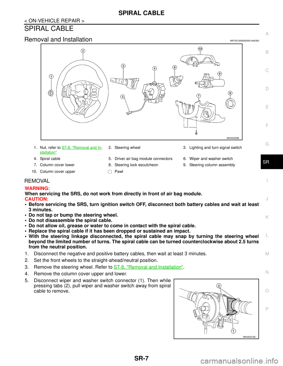
WHIA0339E
1. Nut, refer to ST-8, "Removal and In-
stallation"
2. Steering wheel 3. Lighting and turn signal switch
4. Spiral cable 5. Driver air bag module connectors 6. Wiper and washer switch
7. Column cover lower 8. Steering lock escutcheon 9. Steering column assembly
10. Column cover upper Pawl
WHIA0315E
Page 4863 of 5883

ST-8
< ON-VEHICLE REPAIR >
STEERING WHEEL
ON-VEHICLE REPAIR
STEERING WHEEL
Removal and InstallationINFOID:0000000001282499
REMOVAL
NOTE:
When reconnecting spiral cable, secure cable with a tape so that case and rotating part keep aligned. This will
omit neutral position alignment procedure during spiral cable installation.
1. Set front wheels to straight-ahead position.
2. Remove driver air bag module. Refer to SR-4, "
Removal and Installation" .
3. Remove steering wheel lock nut after steering is locked.
4. Remove steering wheel.
INSTALLATION
Installation is in the reverse order of removal.
CAUTION:
Do not run spiral cable idle needlessly. And do not turn it more than necessary (or it leads to discon-
nection of the cable).
NOTE:
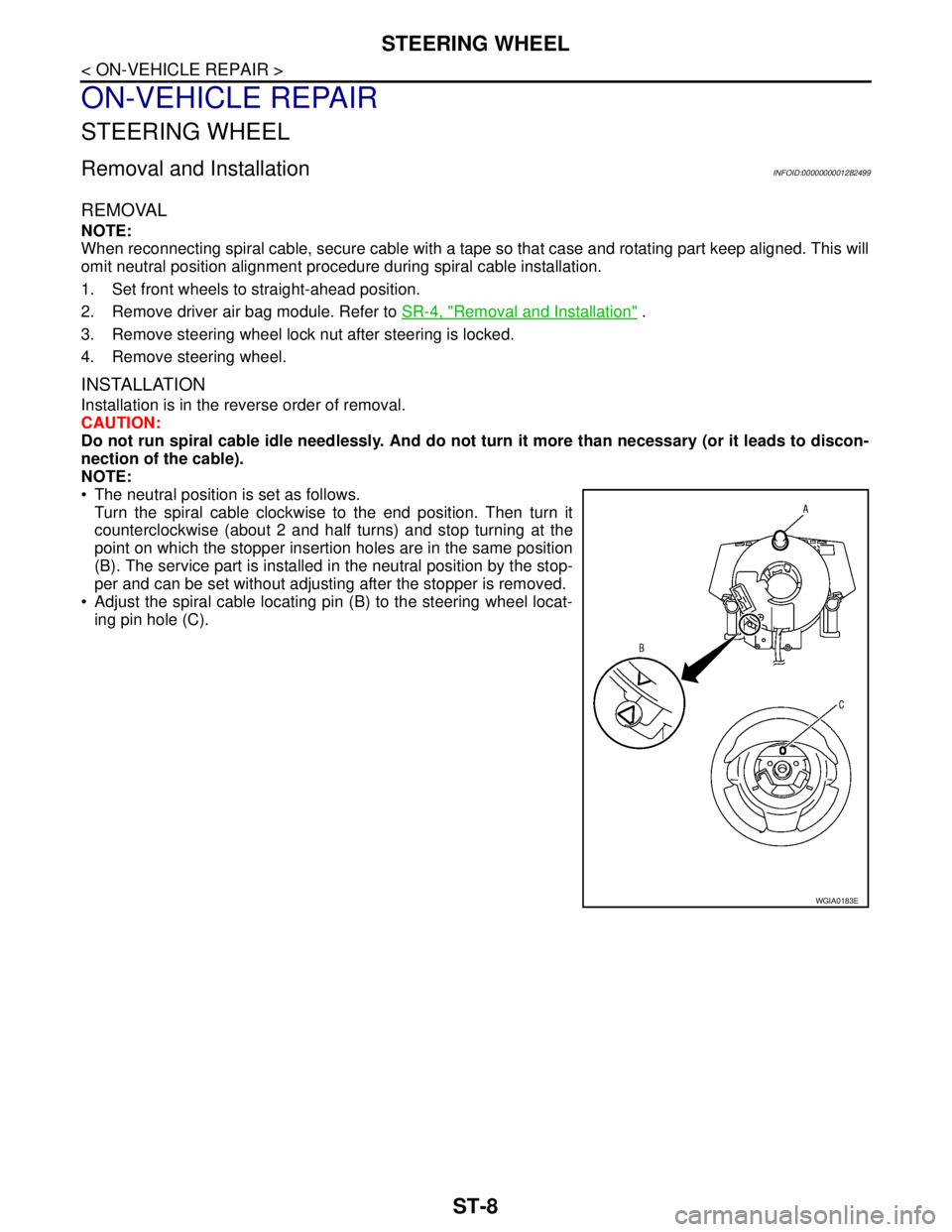
The neutral position is set as follows.
Turn the spiral cable clockwise to the end position. Then turn it
counterclockwise (about 2 and half turns) and stop turning at the
point on which the stopper insertion holes are in the same position
(B). The service part is installed in the neutral position by the stop-
per and can be set without adjusting after the stopper is removed.
Adjust the spiral cable locating pin (B) to the steering wheel locat-
ing pin hole (C).
WGIA0183E
Page 5250 of 5883
TM-304
< DISASSEMBLY AND ASSEMBLY >[TYPE 1 (4AT: RE4F03B)]
ASSEMBLY
6. Install overrun clutch hub (1) into forward clutch drum.
CAUTION:
Align teeth of overrun clutch drive plates before installing.
7. Hold forward clutch hub, and check that rear internal gear locks
when tried to rotate counterclockwise.
CAUTION:
If rear internal gear rotates counterclockwise, check instal-
lation direction of forward one-way clutch.
8. Install needle bearing (1) on rear internal gear (2).
CAUTION:
Be careful with the direction of needle bearing (1).
9. Install rear internal gear (1) and forward clutch hub (2) as a set
into forward clutch drum.
CAUTION:
Align teeth of forward clutch drive plates before installing.
10. Install needle bearing (1) on rear planetary carrier (2).
CAUTION:
Be careful with the direction of needle bearing (1).
SCIA5898J
SCIA7078E
SCIA6041J
SCIA5897J
SCIA5927J
Page 5251 of 5883
ASSEMBLY
TM-305
< DISASSEMBLY AND ASSEMBLY >[TYPE 1 (4AT: RE4F03B)]
C
E
F
G
H
I
J
K
L
MA
B
TM
N
O
P
11. Install rear sun gear on rear planetary carrier.
CAUTION:
Be careful with the direction of rear sun gear.
12. Install rear planetary carrier in transaxle case.
13. Install needle bearing (1) on front planetary carrier (2).
CAUTION:
Be careful with the direction of needle bearing (1).
14. Install low one-way clutch to front planetary carrier by turning it
in the direction of unlock.
15. Check that low one-way clutch rotates counterclockwise around
front planetary carrier. Then try to turn it clockwise and check
that it is locked.
16. Install front planetary carrier (2) and low one-way clutch (1) as a
set into transaxle case.
SAT052D
SAT051D
SCIA6047J
SAT048D
SCIA5896J
Page 5543 of 5883
ASSEMBLY
TM-597
< DISASSEMBLY AND ASSEMBLY >[TYPE 2 (4AT: RE4F03B)]
C
E
F
G
H
I
J
K
L
MA
B
TM
N
O
P
6. Install overrun clutch hub (1) into forward clutch drum.
CAUTION:
Align teeth of overrun clutch drive plates before installing.
7. Hold forward clutch hub, and check that rear internal gear locks
when tried to rotate counterclockwise.
CAUTION:
If rear internal gear rotates counterclockwise, check instal-
lation direction of forward one-way clutch.
8. Install needle bearing (1) on rear internal gear (2).
CAUTION:
Be careful with the direction of needle bearing (1).
9. Install rear internal gear (1) and forward clutch hub (2) as a set
into forward clutch drum.
CAUTION:
Align teeth of forward clutch drive plates before installing.
10. Install needle bearing (1) on rear planetary carrier (2).
CAUTION:
Be careful with the direction of needle bearing (1).
SCIA5898J
SCIA7078E
SCIA6041J
SCIA5897J
SCIA5927J
Page 5544 of 5883
TM-598
< DISASSEMBLY AND ASSEMBLY >[TYPE 2 (4AT: RE4F03B)]
ASSEMBLY
11. Install rear sun gear on rear planetary carrier.
CAUTION:
Be careful with the direction of rear sun gear.
12. Install rear planetary carrier in transaxle case.
13. Install needle bearing (1) on front planetary carrier (2).
CAUTION:
Be careful with the direction of needle bearing (1).
14. Install low one-way clutch to front planetary carrier by turning it
in the direction of unlock.
15. Check that low one-way clutch rotates counterclockwise around
front planetary carrier. Then try to turn it clockwise and check
that it is locked.
16. Install front planetary carrier (2) and low one-way clutch (1) as a
set into transaxle case.
SAT052D
SAT051D
SCIA6047J
SAT048D
SCIA5896J
Page 5586 of 5883
![NISSAN TIIDA 2007 Service Repair Manual TM-640
< DISASSEMBLY AND ASSEMBLY >[5MT: RS5F91R]
TRANSAXLE ASSEMBLY
5. Shift the shift lever (1) of control shaft assembly to 3rd gear posi-
tion.
NOTE:
If not, the transaxle case cannot be removed NISSAN TIIDA 2007 Service Repair Manual TM-640
< DISASSEMBLY AND ASSEMBLY >[5MT: RS5F91R]
TRANSAXLE ASSEMBLY
5. Shift the shift lever (1) of control shaft assembly to 3rd gear posi-
tion.
NOTE:
If not, the transaxle case cannot be removed](/manual-img/5/57395/w960_57395-5585.png)
TM-640
< DISASSEMBLY AND ASSEMBLY >[5MT: RS5F91R]
TRANSAXLE ASSEMBLY
5. Shift the shift lever (1) of control shaft assembly to 3rd gear posi-
tion.
NOTE:
If not, the transaxle case cannot be removed from clutch hous-
ing.
3rd gear position means that the shift lever of control shaft
assembly is fully rotated clockwise and it is returned approxi-
mately 10°.
6. Push in the 5th-reverse shift fork (1), and then shift it to 5th gear
position.
NOTE:
When it is shifted to the 5th gear and 3rd gear at the same time,
the input shaft and mainshaft may not be rotated.
7. Remove mainshaft bolt (2) and input shaft nut (3).
CAUTION:
When mainshaft bolt and input shaft nut are removed, do
not use a power tool in order to prevent the gear from being
damaged.
8. Remove reverse gear gate assembly (4) bolts.
9. Remove retaining pin from 5th-reverse shift fork (1) using a pin
punch.
10. Remove 5th-reverse shift fork (1), reverse gear gate assembly (4) and 5th-reverse coupling sleeve from
5th-reverse synchronizer hub.
11. Remove 5th-reverse synchronizer hub from input shaft using a
puller.
CAUTION:
Set the claw of the puller to the large width side of the hub
when setting the puller in synchronizer hub.
12. Remove 5th baulk ring and 5th input gear.
13. Remove 5th main gear from input shaft using Tools (A) and (B).
PCIB1524E
PCIB1525E
PCIB1526E
Tool number A: KV32300QAC
Tool number B: KV32300QAD
PCIB1527E