2007 NISSAN TIIDA front cowl
[x] Cancel search: front cowlPage 3106 of 5883
EXT-2
< PRECAUTION >
PRECAUTIONS
PRECAUTION
PRECAUTIONS
Precaution for Supplemental Restraint System (SRS) "AIR BAG" and "SEAT BELT
PRE-TENSIONER"
INFOID:0000000001568917
The Supplemental Restraint System such as “AIR BAG” and “SEAT BELT PRE-TENSIONER”, used along
with a front seat belt, helps to reduce the risk or severity of injury to the driver and front passenger for certain
types of collision. This system includes seat belt switch inputs and dual stage front air bag modules. The SRS
system uses the seat belt switches to determine the front air bag deployment, and may only deploy one front
air bag, depending on the severity of a collision and whether the front occupants are belted or unbelted.
Information necessary to service the system safely is included in the SRS and SB section of this Service Man-
ual.
WARNING:
• To avoid rendering the SRS inoperative, which could increase the risk of personal injury or death in
the event of a collision which would result in air bag inflation, all maintenance must be performed by
an authorized NISSAN/INFINITI dealer.
Improper maintenance, including incorrect removal and installation of the SRS, can lead to personal
injury caused by unintentional activation of the system. For removal of Spiral Cable and Air Bag
Module, see the SRS section.
Do not use electrical test equipment on any circuit related to the SRS unless instructed to in this
Service Manual. SRS wiring harnesses can be identified by yellow and/or orange harnesses or har-
ness connectors.
PrecautionINFOID:0000000001568918
When removing or disassembling any part, be careful not to damage or deform it. Protect parts which may
get in the way with cloth.
When removing parts with a screwdriver or other tool, protect parts by wrapping them with vinyl or tape.
Keep removed parts protected with cloth.
If a clip is deformed or damaged, replace it.
If an unreusable part is removed, replace it with a new one.
Tighten bolts and nuts firmly to the specified torque.
After re-assembly has been completed, make sure each part functions correctly.
Remove stains in the following way.
- Water-soluble stains:
Dip a cloth in warm water, and squeeze tightly. After wiping the stain, wipe with a soft dry cloth.
- Oil stain:
Dissolve a synthetic detergent in warm water (density of 2 to 3% or less), dip the cloth, then clean off the
stain with the cloth. Next, dip the soft cloth in fresh water, and then squeeze it tightly. Then clean off the
detergent completely. Then wipe the area with a soft dry cloth.
Do not use any organic solvent, such as thinner or benzine.
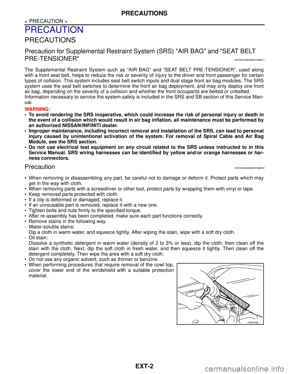
When performing procedures that require removal of the cowl top,
cover the lower end of the windshield with a suitable protection
material.
PIIB3706J
Page 3124 of 5883
EXT-20
< ON-VEHICLE REPAIR >
COWL TOP
COWL TOP
Removal and InstallationINFOID:0000000001568930
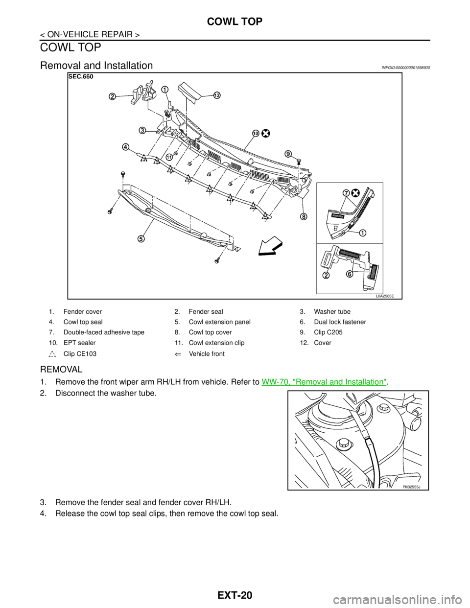
REMOVAL
1. Remove the front wiper arm RH/LH from vehicle. Refer to WW-70, "Removal and Installation".
2. Disconnect the washer tube.
3. Remove the fender seal and fender cover RH/LH.
4. Release the cowl top seal clips, then remove the cowl top seal.
LIIA2565E
1. Fender cover 2. Fender seal 3. Washer tube
4. Cowl top seal 5. Cowl extension panel 6. Dual lock fastener
7. Double-faced adhesive tape 8. Cowl top cover 9. Clip C205
10. EPT sealer 11. Cowl extension clip 12. Cover
Clip CE103⇐Vehicle front
PIIB2555J
Page 3125 of 5883
COWL TOP
EXT-21
< ON-VEHICLE REPAIR >
C
D
E
F
G
H
I
J
L
MA
B
EXT
N
O
P
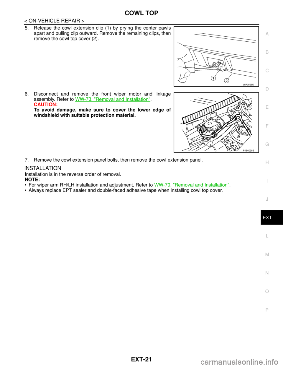
5. Release the cowl extension clip (1) by prying the center pawls
apart and pulling clip outward. Remove the remaining clips, then
remove the cowl top cover (2).
6. Disconnect and remove the front wiper motor and linkage
assembly. Refer to WW-73, "
Removal and Installation".
CAUTION:
To avoid damage, make sure to cover the lower edge of
windshield with suitable protection material.
7. Remove the cowl extension panel bolts, then remove the cowl extension panel.
INSTALLATION
Installation is in the reverse order of removal.
NOTE:
For wiper arm RH/LH installation and adjustment, Refer to WW-70, "
Removal and Installation".
Always replace EPT sealer and double-faced adhesive tape when installing cowl top cover.
LIIA2566E
PIIB6038E
Page 3177 of 5883
FSU-1
SUSPENSION
C
D
F
G
H
I
J
K
L
M
SECTION FSU
A
B
FSU
N
O
PCONTENTS
FRONT SUSPENSION
PRECAUTION ...............................................2
PRECAUTIONS ...................................................2
Precaution for Supplemental Restraint System
(SRS) "AIR BAG" and "SEAT BELT PRE-TEN-
SIONER" ...................................................................
2
Precaution for Procedure without Cowl Top Cover ......2
Cautions ....................................................................2
PREPARATION ............................................3
PREPARATION ...................................................3
Special Service Tool .................................................3
Commercial Service Tool ..........................................4
SYMPTOM DIAGNOSIS ...............................5
NOISE, VIBRATION AND HARSHNESS
(NVH) TROUBLESHOOTING .............................
5
NVH Troubleshooting Chart ......................................5
ON-VEHICLE MAINTENANCE .....................6
FRONT SUSPENSION ASSEMBLY ...................6
On-Vehicle Inspection and Service ...........................6
Wheel Alignment Inspection ......................................6
ON-VEHICLE REPAIR ..................................9
FRONT SUSPENSION ASSEMBLY ...................9
Component ...............................................................9
REMOVAL AND INSTALLATION ...............11
FRONT SUSPENSION ASSEMBLY .................11
Removal and Installation .........................................11
COIL SPRING AND STRUT ..............................12
Removal and Installation .........................................12
TRANSVERSE LINK .........................................13
Removal and Installation .........................................13
STABILIZER BAR .............................................14
Removal and Installation .........................................14
DISASSEMBLY AND ASSEMBLY ..............15
COIL SPRING AND STRUT ..............................15
Disassembly and Assembly .....................................15
SERVICE DATA AND SPECIFICATIONS
(SDS) ............................................................
17
SERVICE DATA AND SPECIFICATIONS
(SDS) .................................................................
17
Wheel Alignment (Unladen*) ...................................17
Ball Joint ..................................................................18
Wheelarch Height (Unladen*) ..................................18
Page 3178 of 5883
FSU-2
< PRECAUTION >
PRECAUTIONS
PRECAUTION
PRECAUTIONS
Precaution for Supplemental Restraint System (SRS) "AIR BAG" and "SEAT BELT
PRE-TENSIONER"
INFOID:0000000001716875
The Supplemental Restraint System such as “AIR BAG” and “SEAT BELT PRE-TENSIONER”, used along
with a front seat belt, helps to reduce the risk or severity of injury to the driver and front passenger for certain
types of collision. This system includes seat belt switch inputs and dual stage front air bag modules. The SRS
system uses the seat belt switches to determine the front air bag deployment, and may only deploy one front
air bag, depending on the severity of a collision and whether the front occupants are belted or unbelted.
Information necessary to service the system safely is included in the SR and SB section of this Service Man-
ual.
WARNING:
• To avoid rendering the SRS inoperative, which could increase the risk of personal injury or death in
the event of a collision which would result in air bag inflation, all maintenance must be performed by
an authorized NISSAN/INFINITI dealer.
Improper maintenance, including incorrect removal and installation of the SRS, can lead to personal
injury caused by unintentional activation of the system. For removal of Spiral Cable and Air Bag
Module, see the SR section.
Do not use electrical test equipment on any circuit related to the SRS unless instructed to in this
Service Manual. SRS wiring harnesses can be identified by yellow and/or orange harnesses or har-
ness connectors.
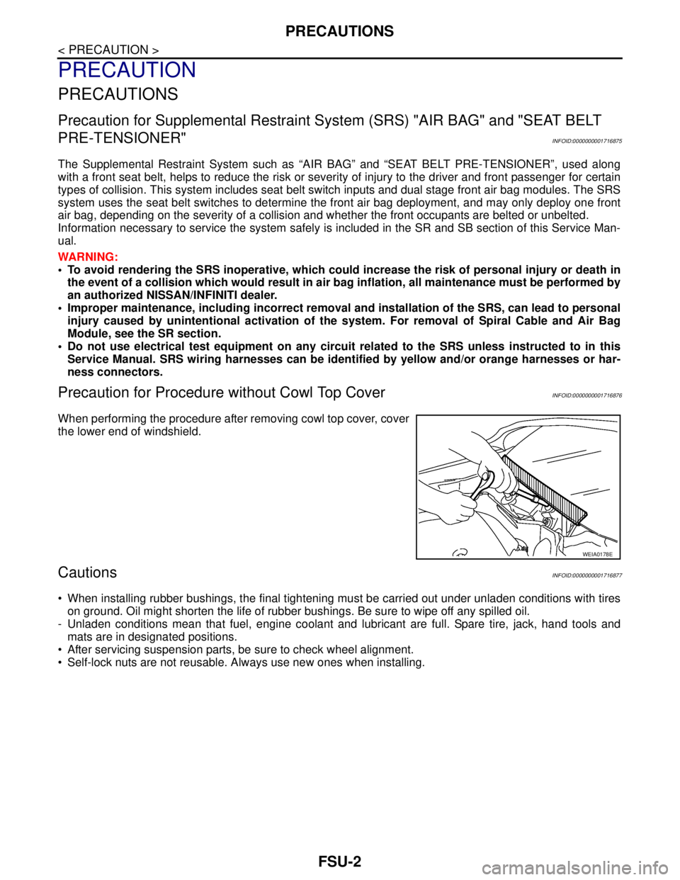
Precaution for Procedure without Cowl Top CoverINFOID:0000000001716876
When performing the procedure after removing cowl top cover, cover
the lower end of windshield.
CautionsINFOID:0000000001716877
When installing rubber bushings, the final tightening must be carried out under unladen conditions with tires
on ground. Oil might shorten the life of rubber bushings. Be sure to wipe off any spilled oil.
- Unladen conditions mean that fuel, engine coolant and lubricant are full. Spare tire, jack, hand tools and
mats are in designated positions.
After servicing suspension parts, be sure to check wheel alignment.
Self-lock nuts are not reusable. Always use new ones when installing.
WEIA0178E
Page 3188 of 5883
FSU-12
< REMOVAL AND INSTALLATION >
COIL SPRING AND STRUT
COIL SPRING AND STRUT
Removal and InstallationINFOID:0000000001716888
REMOVAL
1. Remove cowl top panel. Refer to EXT-20, "Removal and Installation" .
2. Remove front tires using power tool.
3. Remove harness of wheel sensor from strut assembly. Refer to BRC-182, "
Removal and Installation" .
CAUTION:
Do not pull on wheel sensor harness.
4. Remove brake hose lock plate. Refer to BR-14, "
Front Brake Tube and Hose" .
5. Remove the nut on the upper side of stabilizer connecting rod using power tool, and then remove stabi-
lizer connecting rod from strut assembly.
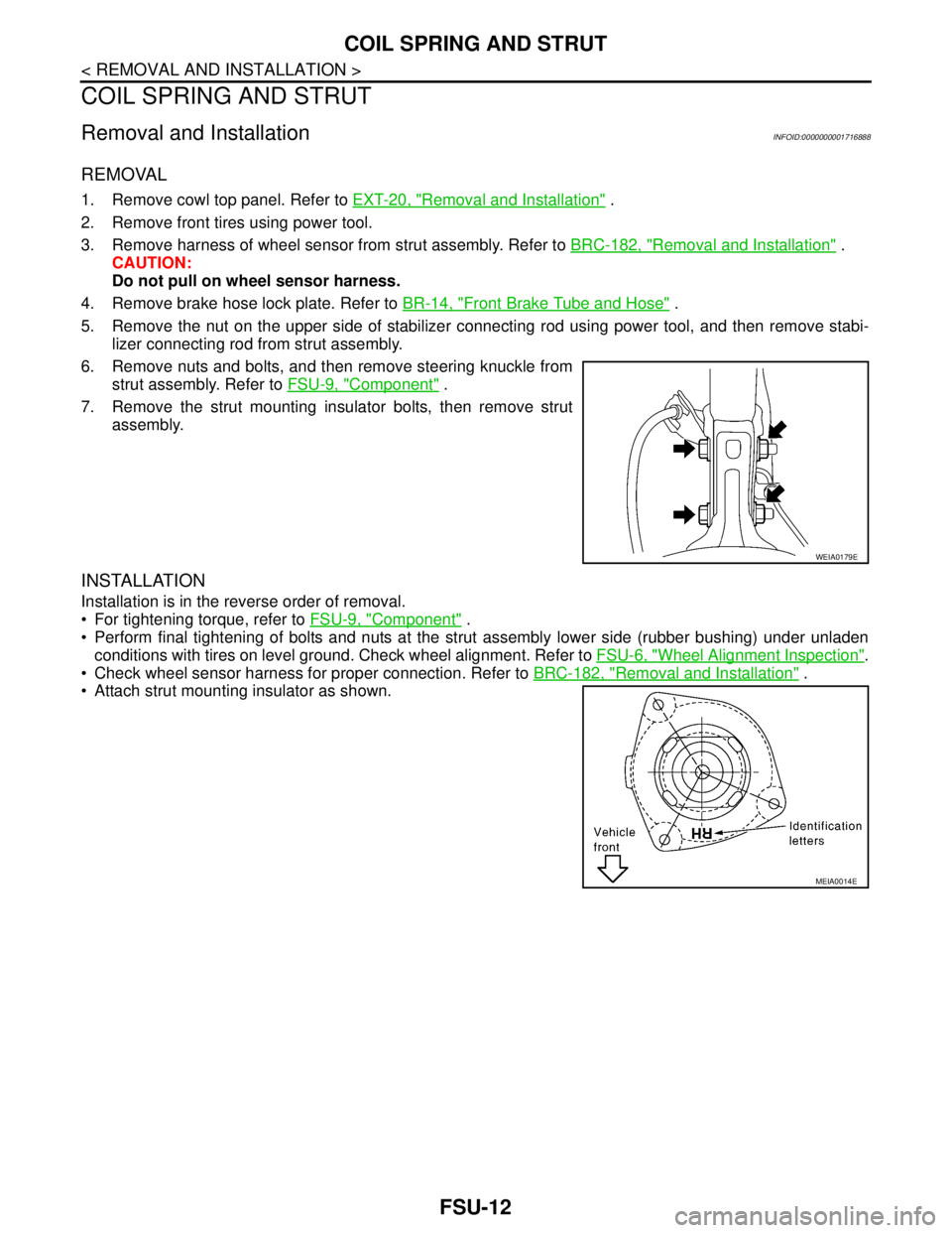
6. Remove nuts and bolts, and then remove steering knuckle from
strut assembly. Refer to FSU-9, "
Component" .
7. Remove the strut mounting insulator bolts, then remove strut
assembly.
INSTALLATION
Installation is in the reverse order of removal.
For tightening torque, refer to FSU-9, "
Component" .
Perform final tightening of bolts and nuts at the strut assembly lower side (rubber bushing) under unladen
conditions with tires on level ground. Check wheel alignment. Refer to FSU-6, "
Wheel Alignment Inspection".
Check wheel sensor harness for proper connection. Refer to BRC-182, "
Removal and Installation" .
Attach strut mounting insulator as shown.
WEIA0179E
MEIA0014E
Page 3260 of 5883

GW-1
BODY EXTERIOR, DOORS, ROOF & VEHICLE SECURITY
C
D
E
F
G
H
I
J
L
M
SECTION GW
A
B
GW
N
O
P
CONTENTS
GLASS & WINDOW SYSTEM
SYMPTOM DIAGNOSIS ...............................2
SQUEAK AND RATTLE TROUBLE DIAG-
NOSES ................................................................
2
Work Flow .................................................................2
Generic Squeak and Rattle Troubleshooting ............4
Diagnostic Worksheet ...............................................6
PRECAUTION ...............................................8
PRECAUTIONS ...................................................8
Precaution for Supplemental Restraint System
(SRS) "AIR BAG" and "SEAT BELT PRE-TEN-
SIONER" ...................................................................
8
Precaution for Procedure without Cowl Top Cover ......8
Handling for Adhesive and Primer ............................8
PREPARATION ............................................9
PREPARATION ...................................................9
Commercial Service Tool ..........................................9
ON-VEHICLE REPAIR .................................10
WINDSHIELD GLASS .......................................10
Removal and Installation .........................................10
OPERA WINDOW GLASS ................................12
Removal and Installation .........................................12
FRONT DOOR GLASS AND REGULATOR .....14
Removal and Installation .........................................14
Disassembly and Assembly .....................................16
Inspection after Installation ......................................16
REAR WINDOW GLASS AND MOLDING ........18
Removal and Installation .........................................18
REAR DOOR GLASS AND REGULATOR .......21
Removal and Installation .........................................21
Disassembly and Assembly .....................................23
Inspection after Installation ......................................23
Page 3267 of 5883
GW-8
< PRECAUTION >
PRECAUTIONS
PRECAUTION
PRECAUTIONS
Precaution for Supplemental Restraint System (SRS) "AIR BAG" and "SEAT BELT
PRE-TENSIONER"
INFOID:0000000001716811
The Supplemental Restraint System such as “AIR BAG” and “SEAT BELT PRE-TENSIONER”, used along
with a front seat belt, helps to reduce the risk or severity of injury to the driver and front passenger for certain
types of collision. Information necessary to service the system safely is included in the SRS and SB section of
this Service Manual.
WARNING:
• To avoid rendering the SRS inoperative, which could increase the risk of personal injury or death in
the event of a collision which would result in air bag inflation, all maintenance must be performed by
an authorized NISSAN/INFINITI dealer.
Improper maintenance, including incorrect removal and installation of the SRS, can lead to personal
injury caused by unintentional activation of the system. For removal of Spiral Cable and Air Bag
Module, see the SRS section.
Do not use electrical test equipment on any circuit related to the SRS unless instructed to in this
Service Manual. SRS wiring harnesses can be identified by yellow and/or orange harnesses or har-
ness connectors.
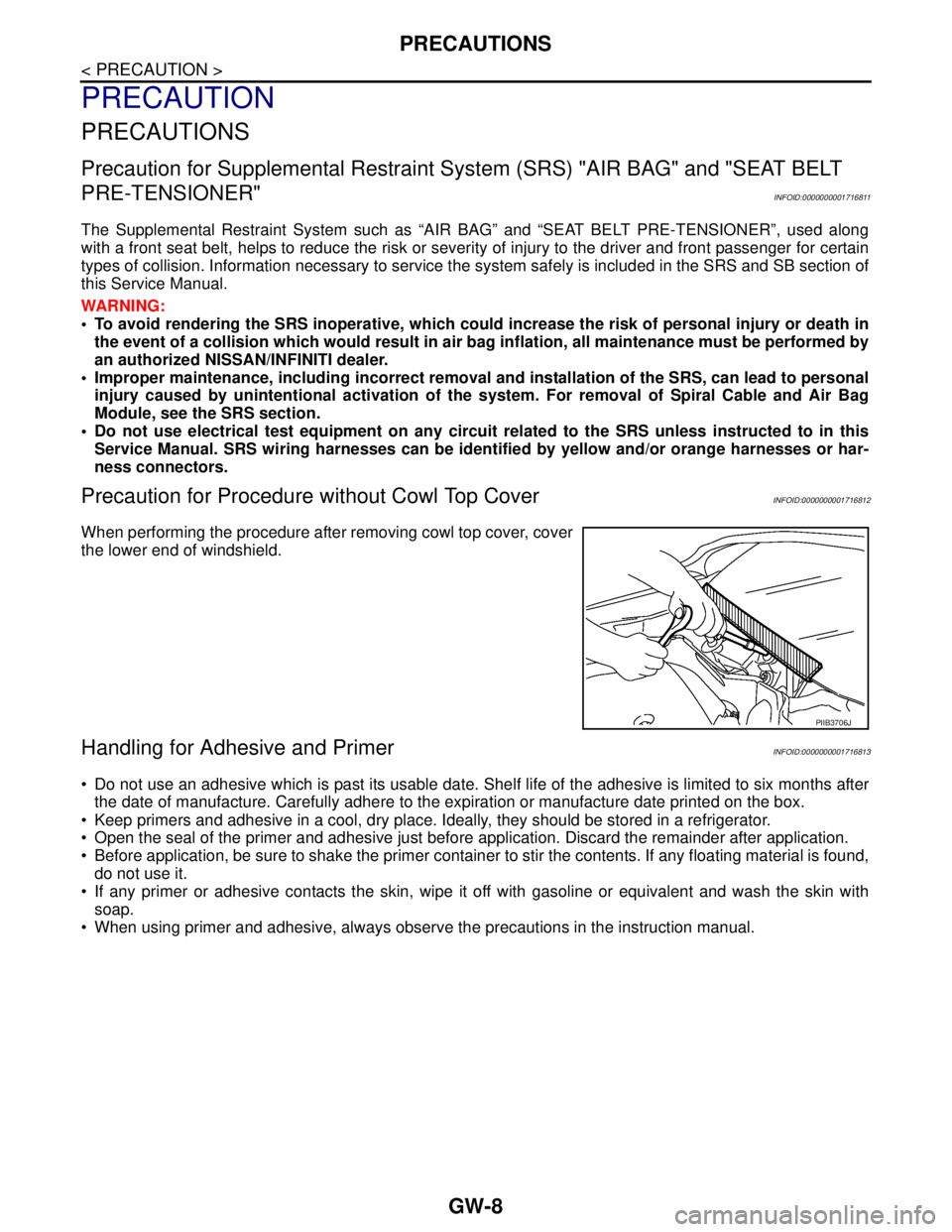
Precaution for Procedure without Cowl Top CoverINFOID:0000000001716812
When performing the procedure after removing cowl top cover, cover
the lower end of windshield.
Handling for Adhesive and PrimerINFOID:0000000001716813
Do not use an adhesive which is past its usable date. Shelf life of the adhesive is limited to six months after
the date of manufacture. Carefully adhere to the expiration or manufacture date printed on the box.
Keep primers and adhesive in a cool, dry place. Ideally, they should be stored in a refrigerator.
Open the seal of the primer and adhesive just before application. Discard the remainder after application.
Before application, be sure to shake the primer container to stir the contents. If any floating material is found,
do not use it.
If any primer or adhesive contacts the skin, wipe it off with gasoline or equivalent and wash the skin with
soap.
When using primer and adhesive, always observe the precautions in the instruction manual.
PIIB3706J