2007 NISSAN TIIDA front cowl
[x] Cancel search: front cowlPage 3532 of 5883
![NISSAN TIIDA 2007 Service Repair Manual PRECAUTIONS
HAC-199
< PRECAUTION >[AUTO AIR CONDITIONER (W/O NAVI)]
C
D
E
F
G
H
J
K
L
MA
B
HAC
N
O
P
PRECAUTION
PRECAUTIONS
Precaution for Supplemental Restraint System (SRS) "AIR BAG" and "SEAT BELT NISSAN TIIDA 2007 Service Repair Manual PRECAUTIONS
HAC-199
< PRECAUTION >[AUTO AIR CONDITIONER (W/O NAVI)]
C
D
E
F
G
H
J
K
L
MA
B
HAC
N
O
P
PRECAUTION
PRECAUTIONS
Precaution for Supplemental Restraint System (SRS) "AIR BAG" and "SEAT BELT](/manual-img/5/57395/w960_57395-3531.png)
PRECAUTIONS
HAC-199
< PRECAUTION >[AUTO AIR CONDITIONER (W/O NAVI)]
C
D
E
F
G
H
J
K
L
MA
B
HAC
N
O
P
PRECAUTION
PRECAUTIONS
Precaution for Supplemental Restraint System (SRS) "AIR BAG" and "SEAT BELT
PRE-TENSIONER"
INFOID:0000000001548138
The Supplemental Restraint System such as “AIR BAG” and “SEAT BELT PRE-TENSIONER”, used along
with a front seat belt, helps to reduce the risk or severity of injury to the driver and front passenger for certain
types of collision. Information necessary to service the system safely is included in the SRS and SB section of
this Service Manual.
WARNING:
To avoid rendering the SRS inoperative, which could increase the risk of personal injury or death in
the event of a collision which would result in air bag inflation, all maintenance must be performed by
an authorized NISSAN/INFINITI dealer.
Improper maintenance, including incorrect removal and installation of the SRS, can lead to personal
injury caused by unintentional activation of the system. For removal of Spiral Cable and Air Bag
Module, see the SRS section.
Do not use electrical test equipment on any circuit related to the SRS unless instructed to in this
Service Manual. SRS wiring harnesses can be identified by yellow and/or orange harnesses or har-
ness connectors.
Precaution for Procedures Without Cowl Top CoverINFOID:0000000001548139
When performing the procedure after removing cowl top cover, cover
the lower end of windshield with urethane, etc.
Working with HFC-134a (R-134a)INFOID:0000000001547461
WARNING:
CFC-12 (R-12) refrigerant and HFC-134a (R-134a) refrigerant are not compatible. If the refrigerants
are mixed compressor failure is likely to occur. Refer to XX-XX, "*****"
. To determine the purity of
HFC-134a (R-134a) in the vehicle and recovery tank, use Refrigerant Recovery/Recycling Recharging
equipment and Refrigerant Identifier.
Use only specified oil for the HFC-134a (R-134a) A/C system and HFC-134a (R-134a) components. If
oil other than that specified is used, compressor failure is likely to occur.
The specified HFC-134a (R-134a) oil rapidly absorbs moisture from the atmosphere. The following
handling precautions must be observed:
- When removing refrigerant components from a vehicle, immediately cap (seal) the component to
minimize the entry of moisture from the atmosphere.
- When installing refrigerant components to a vehicle, do not remove the caps (unseal) until just
before connecting the components. Connect all refrigerant loop components as quickly as possible
to minimize the entry of moisture into system.
- Only use the specified oil from a sealed container. Immediately reseal containers of oil. Without
proper sealing, oil will become moisture saturated and should not be used.
- Avoid breathing A/C refrigerant and oil vapor or mist. Exposure may irritate eyes, nose and throat.
Remove HFC-134a (R-134a) from the A/C system using certified service equipment meeting require-
ments of SAE J2210 [HFC-134a (R-134a) recycling equipment], or J2209 [HFC-134a (R-134a) recy-
cling equipment], If accidental system discharge occurs, ventilate work area before resuming
service. Additional health and safety information may be obtained from refrigerant and oil manufac-
turers.
PIIB3706J
Page 3646 of 5883
![NISSAN TIIDA 2007 Service Repair Manual PRECAUTIONS
HAC-313
< PRECAUTION >[AUTO AIR CONDITIONER (W/NAVI)]
C
D
E
F
G
H
J
K
L
MA
B
HAC
N
O
P
PRECAUTION
PRECAUTIONS
Precaution for Supplemental Restraint System (SRS) "AIR BAG" and "SEAT BELT
P NISSAN TIIDA 2007 Service Repair Manual PRECAUTIONS
HAC-313
< PRECAUTION >[AUTO AIR CONDITIONER (W/NAVI)]
C
D
E
F
G
H
J
K
L
MA
B
HAC
N
O
P
PRECAUTION
PRECAUTIONS
Precaution for Supplemental Restraint System (SRS) "AIR BAG" and "SEAT BELT
P](/manual-img/5/57395/w960_57395-3645.png)
PRECAUTIONS
HAC-313
< PRECAUTION >[AUTO AIR CONDITIONER (W/NAVI)]
C
D
E
F
G
H
J
K
L
MA
B
HAC
N
O
P
PRECAUTION
PRECAUTIONS
Precaution for Supplemental Restraint System (SRS) "AIR BAG" and "SEAT BELT
PRE-TENSIONER"
INFOID:0000000001548120
The Supplemental Restraint System such as “AIR BAG” and “SEAT BELT PRE-TENSIONER”, used along
with a front seat belt, helps to reduce the risk or severity of injury to the driver and front passenger for certain
types of collision. Information necessary to service the system safely is included in the SRS and SB section of
this Service Manual.
WARNING:
To avoid rendering the SRS inoperative, which could increase the risk of personal injury or death in
the event of a collision which would result in air bag inflation, all maintenance must be performed by
an authorized NISSAN/INFINITI dealer.
Improper maintenance, including incorrect removal and installation of the SRS, can lead to personal
injury caused by unintentional activation of the system. For removal of Spiral Cable and Air Bag
Module, see the SRS section.
Do not use electrical test equipment on any circuit related to the SRS unless instructed to in this
Service Manual. SRS wiring harnesses can be identified by yellow and/or orange harnesses or har-
ness connectors.
Precaution for Procedures Without Cowl Top CoverINFOID:0000000001548121
When performing the procedure after removing cowl top cover, cover
the lower end of windshield with urethane, etc.
Working with HFC-134a (R-134a)INFOID:0000000001547383
WARNING:
CFC-12 (R-12) refrigerant and HFC-134a (R-134a) refrigerant are not compatible. If the refrigerants
are mixed compressor failure is likely to occur. Refer to XX-XX, "*****"
. To determine the purity of
HFC-134a (R-134a) in the vehicle and recovery tank, use Refrigerant Recovery/Recycling Recharging
equipment and Refrigerant Identifier.
Use only specified oil for the HFC-134a (R-134a) A/C system and HFC-134a (R-134a) components. If
oil other than that specified is used, compressor failure is likely to occur.
The specified HFC-134a (R-134a) oil rapidly absorbs moisture from the atmosphere. The following
handling precautions must be observed:
- When removing refrigerant components from a vehicle, immediately cap (seal) the component to
minimize the entry of moisture from the atmosphere.
- When installing refrigerant components to a vehicle, do not remove the caps (unseal) until just
before connecting the components. Connect all refrigerant loop components as quickly as possible
to minimize the entry of moisture into system.
- Only use the specified oil from a sealed container. Immediately reseal containers of oil. Without
proper sealing, oil will become moisture saturated and should not be used.
- Avoid breathing A/C refrigerant and oil vapor or mist. Exposure may irritate eyes, nose and throat.
Remove HFC-134a (R-134a) from the A/C system using certified service equipment meeting require-
ments of SAE J2210 [HFC-134a (R-134a) recycling equipment], or J2209 [HFC-134a (R-134a) recy-
cling equipment], If accidental system discharge occurs, ventilate work area before resuming
service. Additional health and safety information may be obtained from refrigerant and oil manufac-
turers.
PIIB3706J
Page 3681 of 5883
INT-2
< PRECAUTION >
PRECAUTIONS
PRECAUTION
PRECAUTIONS
Precaution for Supplemental Restraint System (SRS) "AIR BAG" and "SEAT BELT
PRE-TENSIONER"
INFOID:0000000001530009
The Supplemental Restraint System such as “AIR BAG” and “SEAT BELT PRE-TENSIONER”, used along
with a front seat belt, helps to reduce the risk or severity of injury to the driver and front passenger for certain
types of collision. Information necessary to service the system safely is included in the SR and SB section of
this Service Manual.
WARNING:
• To avoid rendering the SRS inoperative, which could increase the risk of personal injury or death in
the event of a collision which would result in air bag inflation, all maintenance must be performed by
an authorized NISSAN/INFINITI dealer.
Improper maintenance, including incorrect removal and installation of the SRS, can lead to personal
injury caused by unintentional activation of the system. For removal of Spiral Cable and Air Bag
Module, see the SR section.
Do not use electrical test equipment on any circuit related to the SRS unless instructed to in this
Service Manual. SRS wiring harnesses can be identified by yellow and/or orange harnesses or har-
ness connectors.
PrecautionINFOID:0000000001329036
When removing or disassembling any part, be careful not to damage or deform it. Protect parts which may
get in the way with cloth.
When removing parts with a screwdriver or other tool, protect parts by wrapping them with vinyl or tape.
Keep removed parts protected with cloth.
If a clip is deformed or damaged, replace it.
If an unreusable part is removed, replace it with a new one.
Tighten bolts and nuts firmly to the specified torque.
After re-assembly has been completed, make sure each part functions correctly.
Remove stains in the following way.
- Water-soluble stains:
Dip a cloth in warm water, and squeeze tightly. After wiping the stain, wipe with a soft dry cloth.
- Oil stain:
Dissolve a synthetic detergent in warm water (density of 2 to 3% or less), dip the cloth, then clean off the
stain with the cloth. Next, dip the soft cloth in fresh water, and then squeeze it tightly. Then clean off the
detergent completely. Then wipe the area with a soft dry cloth.
Do not use any organic solvent, such as thinner or benzine.
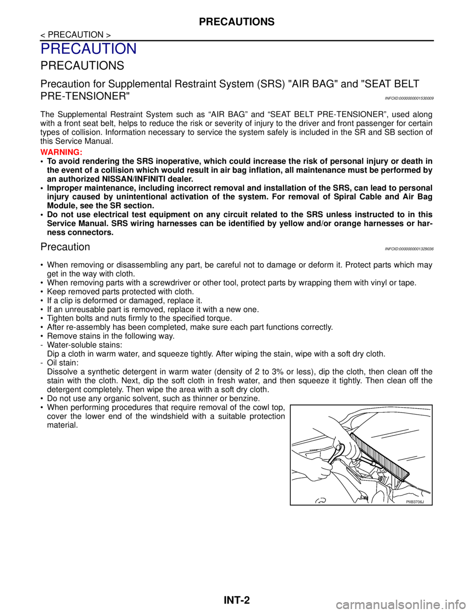
When performing procedures that require removal of the cowl top,
cover the lower end of the windshield with a suitable protection
material.
PIIB3706J
Page 5804 of 5883

WW-2
Wiring Diagram .......................................................36
REAR WIPER AND WASHER SYSTEM ...........41
Wiring Diagram .......................................................41
HEADLAMP WASHER SYSTEM ......................47
Wiring Diagram .......................................................47
ECU DIAGNOSIS ........................................51
BCM (BODY CONTROL MODULE) ..................51
Reference Value .....................................................51
IPDM E/R (INTELLIGENT POWER DISTRI-
BUTION MODULE ENGINE ROOM) .................
52
Reference Value .....................................................52
Fail Safe .................................................................52
SYMPTOM DIAGNOSIS .............................54
WIPER AND WASHER SYSTEM SYMPTOMS
...
54
Symptom Table ......................................................54
NORMAL OPERATING CONDITION ................57
Description ..............................................................57
FRONT WIPER DOES NOT OPERATE ............58
Description ..............................................................58
Diagnosis Procedure ..............................................58
HEADLAMP WASHER DOES NOT OPER-
ATE ....................................................................
60
Description ..............................................................60
Diagnosis Procedure ..............................................60
PRECAUTION .............................................61
PRECAUTIONS .................................................61
Precaution for Supplemental Restraint System
(SRS) "AIR BAG" and "SEAT BELT PRE-TEN-
SIONER" .................................................................
61
Precaution for Procedure without Cowl Top Cover ...61
ON-VEHICLE REPAIR ................................62
HEADLAMP WASHER NOZZLE AND TUBE ...62
Exploded View ........................................................62
Removal and Installation .........................................62
Inspection ................................................................63
WASHER TANK ................................................64
Removal and Installation .........................................64
WASHER PUMP ................................................65
Removal and Installation .........................................65
HEADLAMP WASHER PUMP ..........................66
Removal and Installation .........................................66
FRONT WASHER NOZZLE AND TUBE ...........67
Washer Tube Layout ...............................................67
Removal and Installation .........................................67
Inspection ................................................................67
Adjustment ..............................................................68
FRONT WIPER ARM .........................................69
Exploded View ........................................................69
Removal and Installation .........................................70
Adjustment ..............................................................71
FRONT WIPER DRIVE ASSEMBLY .................72
Exploded View ........................................................72
Removal and Installation .........................................73
Adjustment ..............................................................73
RAIN SENSOR ..................................................75
Exploded View ........................................................75
Removal and Installation .........................................75
WIPER AND WASHER SWITCH ......................76
Exploded View ........................................................76
Removal and Installation .........................................76
REAR WIPER MOTOR ......................................77
Exploded View ........................................................77
Removal and Installation .........................................77
Adjustment ..............................................................78
REAR WASHER NOZZLE AND TUBE .............80
Washer Tube Layout ...............................................80
Removal and Installation .........................................80
Adjustment ..............................................................81
Page 5809 of 5883
FRONT WIPER AND WASHER SYSTEM
WW-7
< FUNCTION DIAGNOSIS >
C
D
E
F
G
H
I
J
K
MA
B
WW
N
O
P
- Front washer switch OFF
BCM transmits the front wiper request signal (LO) to IPDM E/R with CAN communication so that the front
wiper operate once three seconds after front wiper operation linked with washer.
IPDM E/R turns ON the integrated front wiper relay according to the front wiper request signal (LO).
FRONT WIPER FAIL−SAFE OPERATION
IPDM E/R performs the fail-safe function when the front wiper auto stop circuit is malfunctioning. Refer to
WW-52, "
FailSafe".
BCM performs fail-safe operation when light and rain sensor (if equipped) or light and rain sensor-related
systems are malfunctioning. Refer to EXL-55, "
Description".
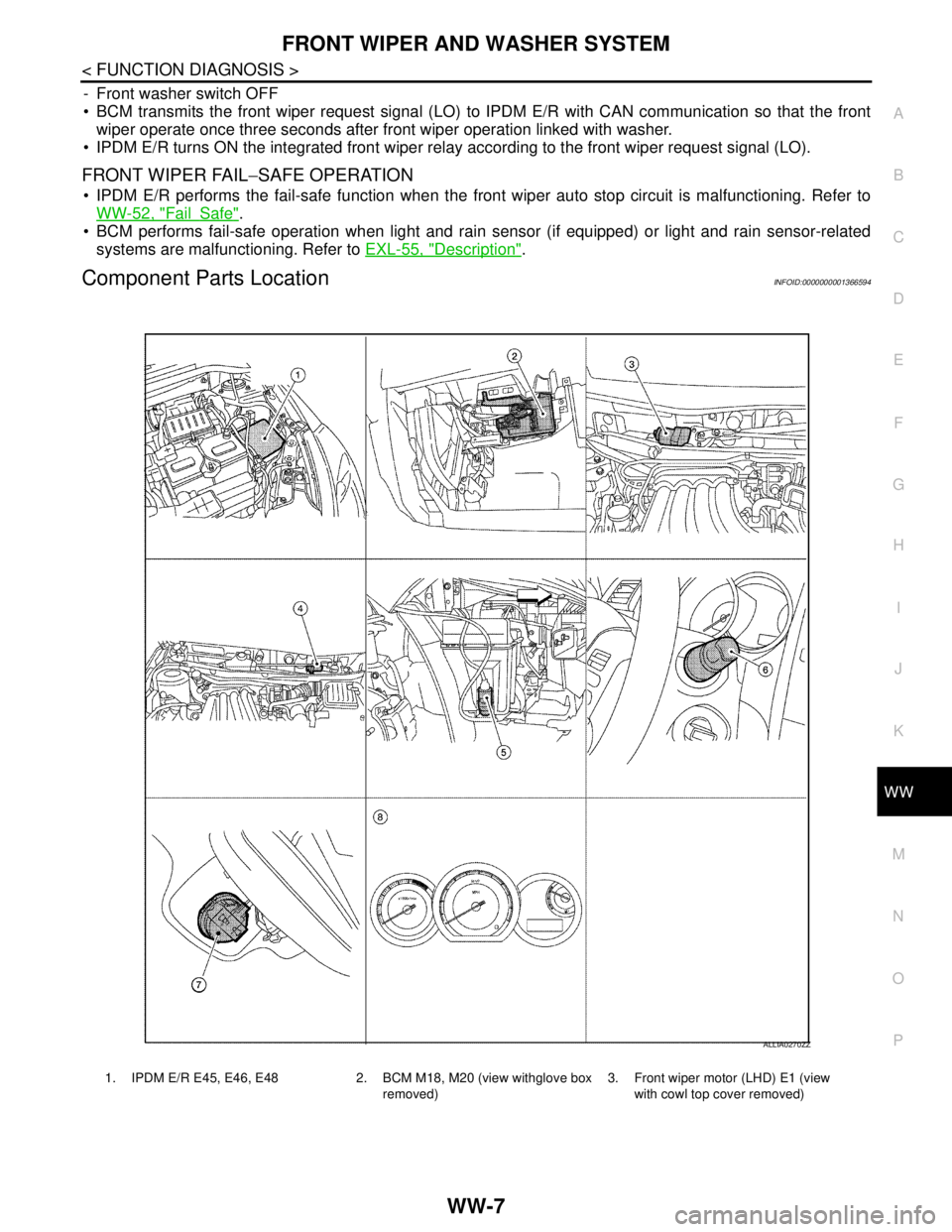
Component Parts LocationINFOID:0000000001366594
1. IPDM E/R E45, E46, E48 2. BCM M18, M20 (view withglove box
removed)3. Front wiper motor (LHD) E1 (view
with cowl top cover removed)
ALLIA0270ZZ
Page 5810 of 5883
WW-8
< FUNCTION DIAGNOSIS >
FRONT WIPER AND WASHER SYSTEM
Component Description
INFOID:0000000001366595
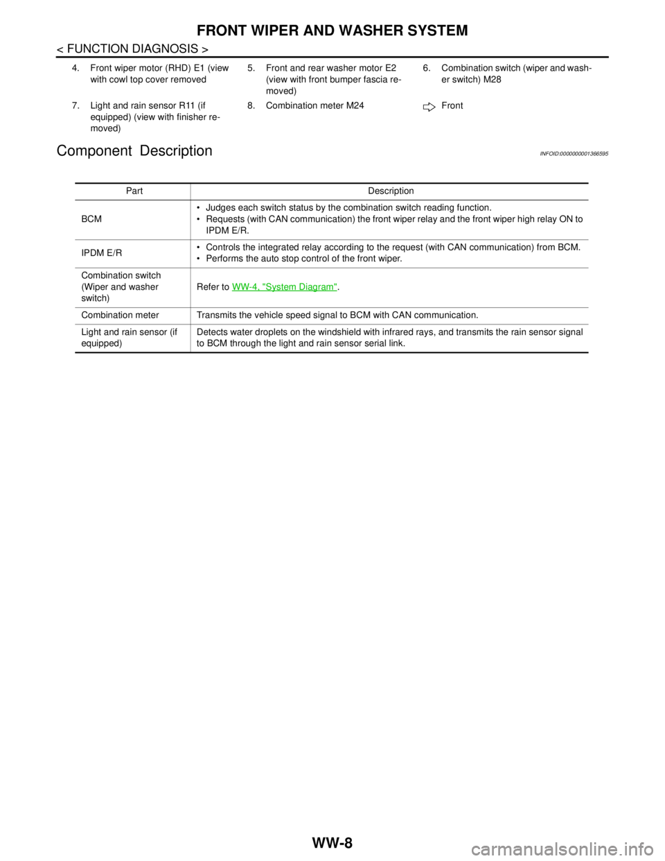
4. Front wiper motor (RHD) E1 (view
with cowl top cover removed5. Front and rear washer motor E2
(view with front bumper fascia re-
moved)6. Combination switch (wiper and wash-
er switch) M28
7. Light and rain sensor R11 (if
equipped) (view with finisher re-
moved)8. Combination meter M24 Front
Part Description
BCM Judges each switch status by the combination switch reading function.
Requests (with CAN communication) the front wiper relay and the front wiper high relay ON to
IPDM E/R.
IPDM E/R Controls the integrated relay according to the request (with CAN communication) from BCM.
Performs the auto stop control of the front wiper.
Combination switch
(Wiper and washer
switch)Refer to WW-4, "
System Diagram".
Combination meter Transmits the vehicle speed signal to BCM with CAN communication.
Light and rain sensor (if
equipped)Detects water droplets on the windshield with infrared rays, and transmits the rain sensor signal
to BCM through the light and rain sensor serial link.
Page 5863 of 5883
PRECAUTIONS
WW-61
< PRECAUTION >
C
D
E
F
G
H
I
J
K
MA
B
WW
N
O
P
PRECAUTION
PRECAUTIONS
Precaution for Supplemental Restraint System (SRS) "AIR BAG" and "SEAT BELT
PRE-TENSIONER"
INFOID:0000000001538893
The Supplemental Restraint System such as “AIR BAG” and “SEAT BELT PRE-TENSIONER”, used along
with a front seat belt, helps to reduce the risk or severity of injury to the driver and front passenger for certain
types of collision. Information necessary to service the system safely is included in the SR and SB section of
this Service Manual.
WARNING:
• To avoid rendering the SRS inoperative, which could increase the risk of personal injury or death in
the event of a collision which would result in air bag inflation, all maintenance must be performed by
an authorized NISSAN/INFINITI dealer.
Improper maintenance, including incorrect removal and installation of the SRS, can lead to personal
injury caused by unintentional activation of the system. For removal of Spiral Cable and Air Bag
Module, see the SR section.
Do not use electrical test equipment on any circuit related to the SRS unless instructed to in this
Service Manual. SRS wiring harnesses can be identified by yellow and/or orange harnesses or har-
ness connectors.
Precaution for Procedure without Cowl Top CoverINFOID:0000000001366647
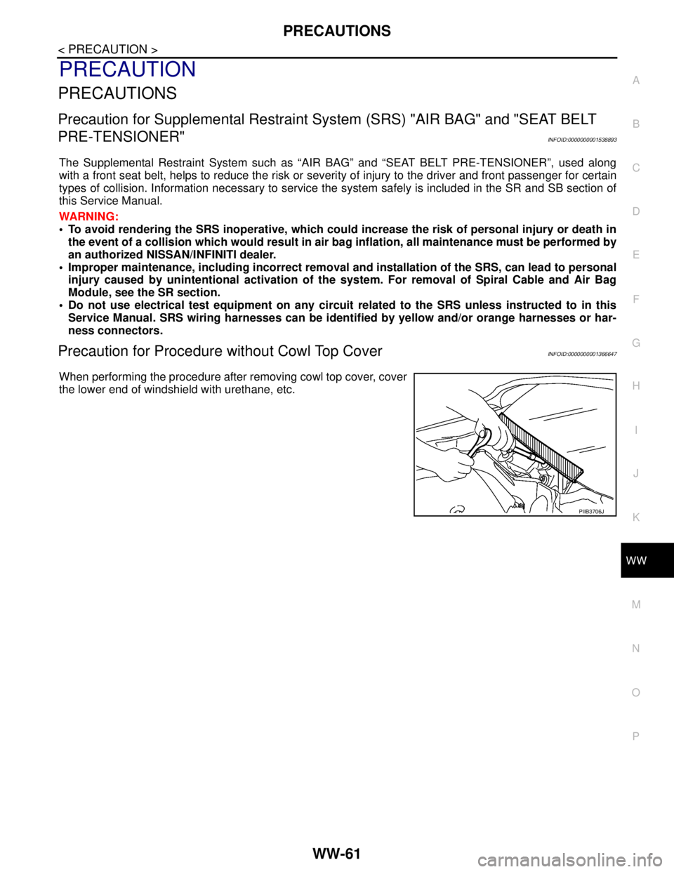
When performing the procedure after removing cowl top cover, cover
the lower end of windshield with urethane, etc.
PIIB3706J
Page 5869 of 5883
FRONT WASHER NOZZLE AND TUBE
WW-67
< ON-VEHICLE REPAIR >
C
D
E
F
G
H
I
J
K
MA
B
WW
N
O
P
FRONT WASHER NOZZLE AND TUBE
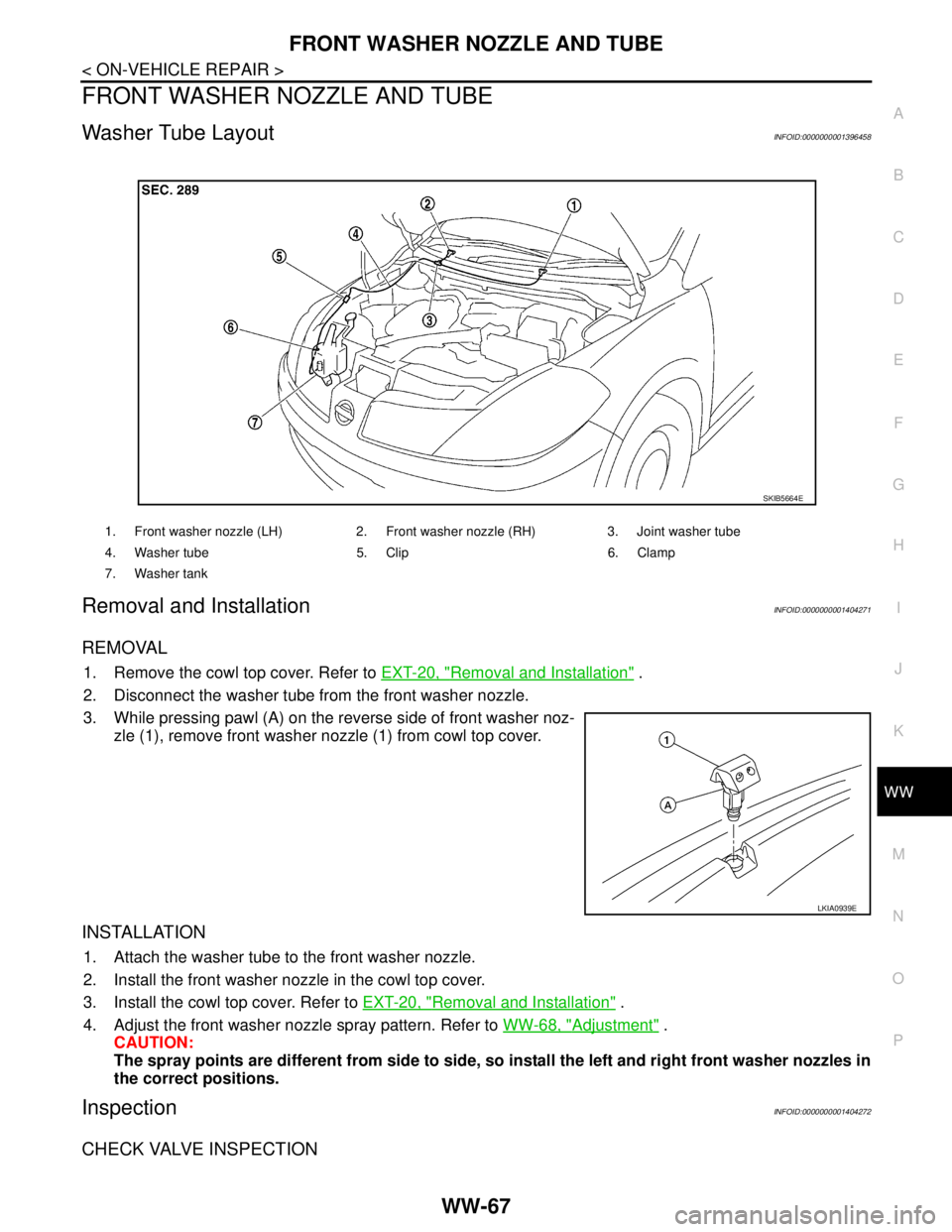
Washer Tube LayoutINFOID:0000000001396458
Removal and InstallationINFOID:0000000001404271
REMOVAL
1. Remove the cowl top cover. Refer to EXT-20, "Removal and Installation" .
2. Disconnect the washer tube from the front washer nozzle.
3. While pressing pawl (A) on the reverse side of front washer noz-
zle (1), remove front washer nozzle (1) from cowl top cover.
INSTALLATION
1. Attach the washer tube to the front washer nozzle.
2. Install the front washer nozzle in the cowl top cover.
3. Install the cowl top cover. Refer to EXT-20, "
Removal and Installation" .
4. Adjust the front washer nozzle spray pattern. Refer to WW-68, "
Adjustment" .
CAUTION:
The spray points are different from side to side, so install the left and right front washer nozzles in
the correct positions.
InspectionINFOID:0000000001404272
CHECK VALVE INSPECTION
1. Front washer nozzle (LH) 2. Front washer nozzle (RH) 3. Joint washer tube
4. Washer tube 5. Clip 6. Clamp
7. Washer tank
SKIB5664E
LKIA0939E