2007 NISSAN TIIDA front cowl
[x] Cancel search: front cowlPage 3269 of 5883

GW-10
< ON-VEHICLE REPAIR >
WINDSHIELD GLASS
ON-VEHICLE REPAIR
WINDSHIELD GLASS
Removal and InstallationINFOID:0000000001716818
REMOVAL
1. Partially remove the headlining (front edge). Refer to INT-31, "Removal and Installation - Hatchback" INT-
33, "Removal and Installation - Sedan".
2. Remove the front wiper arms. Refer to WW-70, "
Removal and Installation".
3. Remove the cowl top cover. Refer to EXT-20, "
Removal and Installation".
4. Disconnect the harness connector of wiper deicer.
5. Apply protective tape around the windshield glass to protect the painted surface from damage.
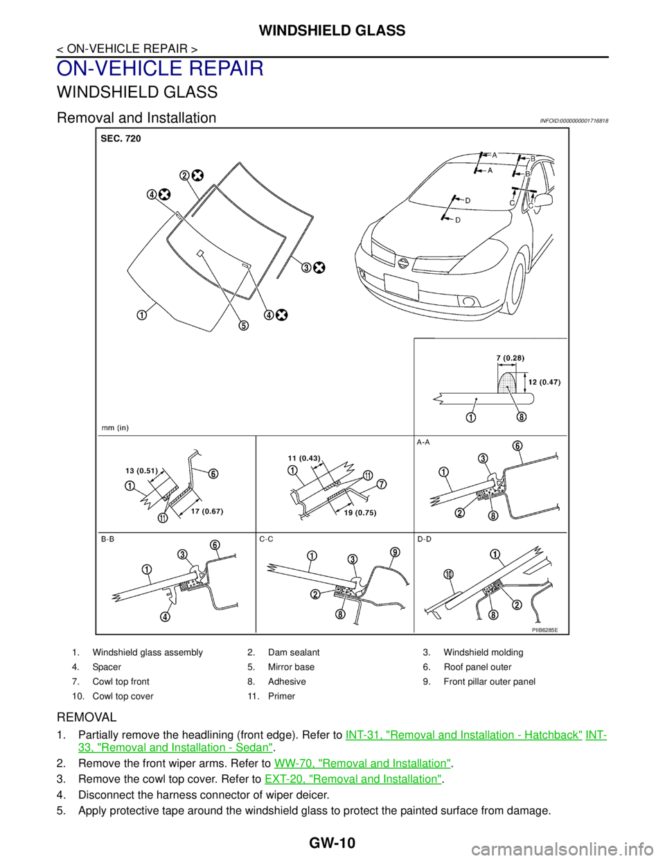
PIIB6285E
1. Windshield glass assembly 2. Dam sealant 3. Windshield molding
4. Spacer 5. Mirror base 6. Roof panel outer
7. Cowl top front 8. Adhesive 9. Front pillar outer panel
10. Cowl top cover 11. Primer
Page 3285 of 5883

PRECAUTIONS
HA-3
< PRECAUTION >
C
D
E
F
G
H
J
K
L
MA
B
HA
N
O
P
PRECAUTION
PRECAUTIONS
Precaution for Supplemental Restraint System (SRS) "AIR BAG" and "SEAT BELT
PRE-TENSIONER"
INFOID:0000000001396449
The Supplemental Restraint System such as “AIR BAG” and “SEAT BELT PRE-TENSIONER”, used along
with a front seat belt, helps to reduce the risk or severity of injury to the driver and front passenger for certain
types of collision. Information necessary to service the system safely is included in the SR and SB section of
this Service Manual.
WARNING:
• To avoid rendering the SRS inoperative, which could increase the risk of personal injury or death in
the event of a collision which would result in air bag inflation, all maintenance must be performed by
an authorized NISSAN/INFINITI dealer.
Improper maintenance, including incorrect removal and installation of the SRS, can lead to personal
injury caused by unintentional activation of the system. For removal of Spiral Cable and Air Bag
Module, see the SR section.
Do not use electrical test equipment on any circuit related to the SRS unless instructed to in this
Service Manual. SRS wiring harnesses can be identified by yellow and/or orange harnesses or har-
ness connectors.
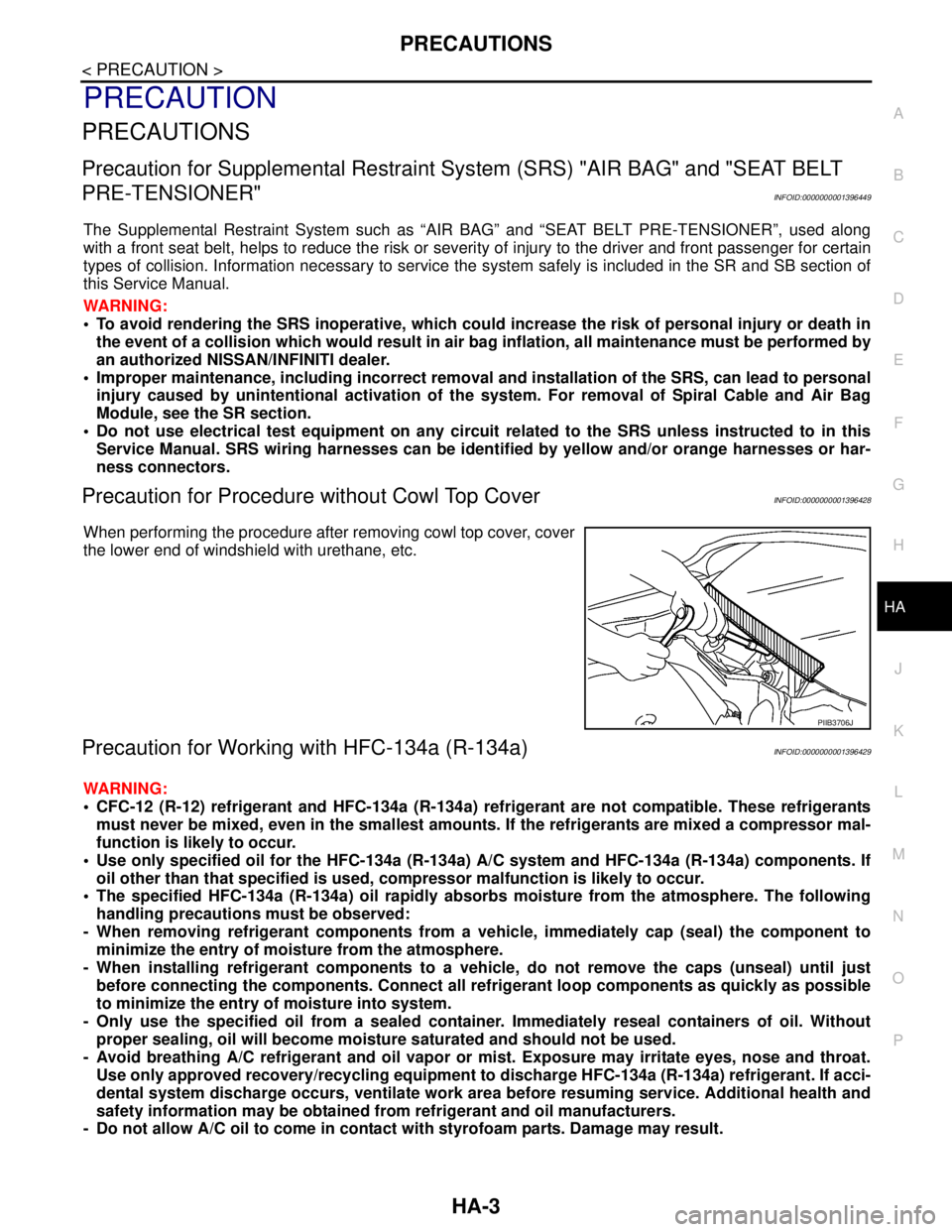
Precaution for Procedure without Cowl Top CoverINFOID:0000000001396428
When performing the procedure after removing cowl top cover, cover
the lower end of windshield with urethane, etc.
Precaution for Working with HFC-134a (R-134a)INFOID:0000000001396429
WARNING:
CFC-12 (R-12) refrigerant and HFC-134a (R-134a) refrigerant are not compatible. These refrigerants
must never be mixed, even in the smallest amounts. If the refrigerants are mixed a compressor mal-
function is likely to occur.
Use only specified oil for the HFC-134a (R-134a) A/C system and HFC-134a (R-134a) components. If
oil other than that specified is used, compressor malfunction is likely to occur.
The specified HFC-134a (R-134a) oil rapidly absorbs moisture from the atmosphere. The following
handling precautions must be observed:
- When removing refrigerant components from a vehicle, immediately cap (seal) the component to
minimize the entry of moisture from the atmosphere.
- When installing refrigerant components to a vehicle, do not remove the caps (unseal) until just
before connecting the components. Connect all refrigerant loop components as quickly as possible
to minimize the entry of moisture into system.
- Only use the specified oil from a sealed container. Immediately reseal containers of oil. Without
proper sealing, oil will become moisture saturated and should not be used.
- Avoid breathing A/C refrigerant and oil vapor or mist. Exposure may irritate eyes, nose and throat.
Use only approved recovery/recycling equipment to discharge HFC-134a (R-134a) refrigerant. If acci-
dental system discharge occurs, ventilate work area before resuming service. Additional health and
safety information may be obtained from refrigerant and oil manufacturers.
- Do not allow A/C oil to come in contact with styrofoam parts. Damage may result.
PIIB3706J
Page 3322 of 5883

HA-40
< ON-VEHICLE REPAIR >
LOW-PRESSURE PIPE
LOW-PRESSURE PIPE
Removal and Installation of Low-Pressure Pipe - K9KINFOID:0000000001404236
REMOVAL
1. Use the recovery/recycling equipment to evacuate the refrigerant. Refer to HA-21, "HFC-134a (R-134a)
Service Procedure".
2. Remove engine cover.
3. Remove cowl top cover. Refer to EXT-20, "
Removal and Installation".
4. Reposition the lower dash insulator out of the way.
5. Remove the front grille. Refer to EXT-19, "
Removal and Installation".
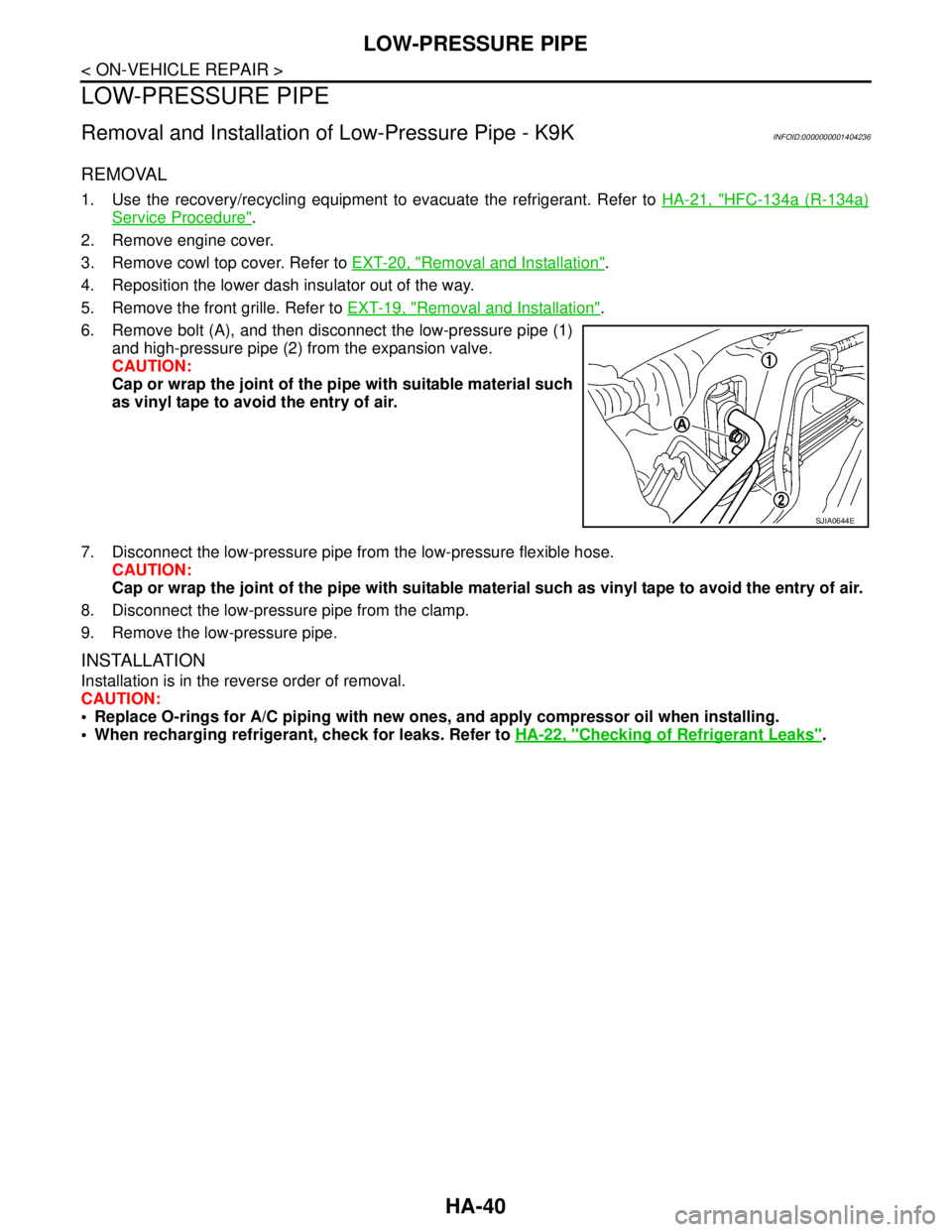
6. Remove bolt (A), and then disconnect the low-pressure pipe (1)
and high-pressure pipe (2) from the expansion valve.
CAUTION:
Cap or wrap the joint of the pipe with suitable material such
as vinyl tape to avoid the entry of air.
7. Disconnect the low-pressure pipe from the low-pressure flexible hose.
CAUTION:
Cap or wrap the joint of the pipe with suitable material such as vinyl tape to avoid the entry of air.
8. Disconnect the low-pressure pipe from the clamp.
9. Remove the low-pressure pipe.
INSTALLATION
Installation is in the reverse order of removal.
CAUTION:
Replace O-rings for A/C piping with new ones, and apply compressor oil when installing.
When recharging refrigerant, check for leaks. Refer to HA-22, "
Checking of Refrigerant Leaks".
SJIA0644E
Page 3325 of 5883

HIGH-PRESSURE PIPE
HA-43
< ON-VEHICLE REPAIR >
C
D
E
F
G
H
J
K
L
MA
B
HA
N
O
P
HIGH-PRESSURE PIPE
Removal and Installation of High-Pressure Pipe - MR18DE, HR16DEINFOID:0000000001404219
REMOVAL
1. Remove low-pressure flexible hose. Refer to HA-38, "Removal and Installation of Low-Pressure Flexible
Hose - MR18DE, HR16DE".
2. Remove high-pressure pipe from the clips.
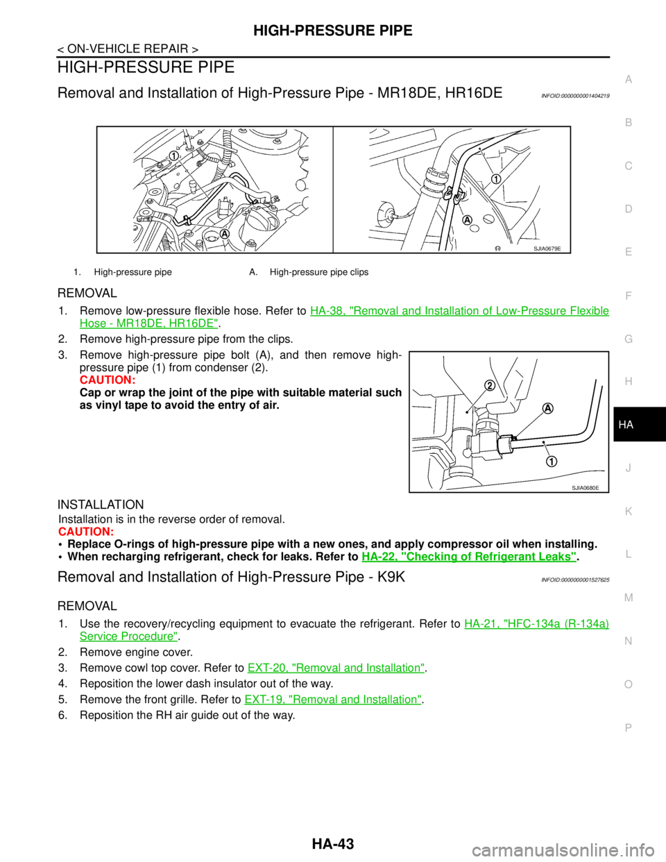
3. Remove high-pressure pipe bolt (A), and then remove high-
pressure pipe (1) from condenser (2).
CAUTION:
Cap or wrap the joint of the pipe with suitable material such
as vinyl tape to avoid the entry of air.
INSTALLATION
Installation is in the reverse order of removal.
CAUTION:
Replace O-rings of high-pressure pipe with a new ones, and apply compressor oil when installing.
When recharging refrigerant, check for leaks. Refer to HA-22, "
Checking of Refrigerant Leaks".
Removal and Installation of High-Pressure Pipe - K9KINFOID:0000000001527625
REMOVAL
1. Use the recovery/recycling equipment to evacuate the refrigerant. Refer to HA-21, "HFC-134a (R-134a)
Service Procedure".
2. Remove engine cover.
3. Remove cowl top cover. Refer to EXT-20, "
Removal and Installation".
4. Reposition the lower dash insulator out of the way.
5. Remove the front grille. Refer to EXT-19, "
Removal and Installation".
6. Reposition the RH air guide out of the way.
1. High-pressure pipe A. High-pressure pipe clips
SJIA0679E
SJIA0680E
Page 3335 of 5883

HAC-2
PTC HEATER CONTROL SYSTEM ..................63
PTC HEATER (300 WATT) .......................................63
PTC HEATER (300 WATT) : Wiring Diagram -
PTC Heater (300 Watt) - .........................................
63
PTC HEATER (1500 WATT) .....................................67
PTC HEATER (1500 WATT) : Wiring Diagram -
PTC Heater (1500 Watt) - .......................................
68
SYMPTOM DIAGNOSIS .............................72
AIR CONDITIONER CONTROL ........................72
Symptom Matrix Chart ..........................................72
INSUFFICIENT COOLING .................................73
Component Function Check ...................................73
Performance Test Diagnoses .................................74
Performance Chart .................................................75
Test Reading ..........................................................76
Trouble Diagnoses for Unusual Pressure ...............77
INSUFFICIENT HEATING .................................81
Component Function Check ...................................81
NOISE ................................................................83
Component Function Check ...................................83
PRECAUTION .............................................84
PRECAUTIONS .................................................84
Precaution for Supplemental Restraint System
(SRS) "AIR BAG" and "SEAT BELT PRE-TEN-
SIONER" .................................................................
84
Precaution for Procedures Without Cowl Top Cov-
er ............................................................................
84
Working with HFC-134a (R-134a) ..........................84
Precaution for Service Equipment ..........................85
AUTO AIR CONDITIONER (W/O NAVI)
BASIC INSPECTION ...................................
86
DIAGNOSIS AND REPAIR WORKFLOW .........86
How to Perform Trouble Diagnosis For Quick And
Accurate Repair ......................................................
86
INSPECTION AND ADJUSTMENT ...................87
Operational Check ..................................................87
FUNCTION DIAGNOSIS .............................89
FUNCTION INFORMATION ..............................89
Component Part Location .......................................89
REFRIGERATION SYSTEM ..............................91
Refrigerant Cycle ....................................................91
Refrigerant System Protection ................................91
AUTOMATIC AIR CONDITIONER SYSTEM .....92
Control System Diagram ........................................92
Control System Description ....................................92
Discharge Air Flow .................................................94
Switches And Their Control Function ......................95
CAN COMMUNICATION SYSTEM ...................96
System Description .................................................96
DIAGNOSIS SYSTEM (BCM) ............................97
CONSULT-III Function (BCM) ................................97
SELF-DIAGNOSIS FUNCTION .........................98
Front Air Control Self-Diagnosis .............................98
A/C System Self-Diagnosis Code Chart ...............104
COMPONENT DIAGNOSIS ......................106
MODE DOOR MOTOR .....................................106
System Description ...............................................106
Mode Door Motor Component Function Check ....107
Mode Door Motor Diagnosis Procedure ................109
AIR MIX DOOR MOTOR ..................................110
System Description ...............................................110
Air Mix Door Motor Component Function Check ..111
Air Mix Door Motor Diagnosis Procedure ..............112
INTAKE DOOR MOTOR ...................................114
System Description ...............................................114
Intake Door Motor Component Function Check ....115
Intake Door Motor Diagnosis Procedure ...............116
BLOWER MOTOR CONTROL SYSTEM .........118
System Description ...............................................118
Front Blower Motor Component Function Check ..119
Front Blower Motor Diagnosis Procedure .............120
Front Blower Motor Component Inspection ..........123
MAGNET CLUTCH ...........................................124
System Description ...............................................124
Magnet Clutch Component Function Check .........124
Magnet Clutch Diagnosis Procedure ....................125
AMBIENT SENSOR ..........................................130
Component Description ........................................130
Ambient Sensor Diagnosis Procedure ..................130
Ambient Sensor Component Inspection ...............131
IN-VEHICLE SENSOR ......................................133
Component Description ........................................133
In-Vehicle Sensor Diagnosis Procedure ...............133
In-Vehicle Sensor Component Inspection .............135
SUNLOAD SENSOR ........................................136
System Description ...............................................136
Sunload Sensor Diagnosis Procedure ..................136
Sunload Component Inspection ............................137
INTAKE SENSOR .............................................139
Component Inspection ..........................................139
Intake Sensor Diagnosis Procedure .....................139
Intake Sensor Component Inspection ...................140
PTC HEATER CONTROL SYSTEM .................142
Page 3336 of 5883

HAC-3
C
D
E
F
G
H
J
K
L
MA
B
HAC
N
O
P PTC HEATER (300 WATT) .....................................
142
PTC HEATER (300 WATT) : PTC Heater System
Description ............................................................
142
PTC HEATER (300 WATT) : PTC Heater Compo-
nent Description ....................................................
143
PTC HEATER (300 WATT) : PTC Heater (300
Watt) Diagnosis Procedure ...................................
144
PTC HEATER (300 WATT) : PTC Heater (300
Watt) Component Inspection .................................
151
PTC HEATER (1500 WATT) ...................................153
PTC HEATER (1500 WATT) : System Description ..153
PTC HEATER (1500 WATT) : Component De-
scription .................................................................
154
PTC HEATER (1500 WATT) : PTC Heater (1500
Watt) Diagnosis Procedure ...................................
155
PTC HEATER (1500 WATT) : PTC Heater (1500
Watt) Component Inspection .................................
160
POWER SUPPLY AND GROUND CIRCUIT
FOR CONTROLLER ........................................
163
Component Description .........................................163
Front Air Control Component Function Check ......163
Front Air Control Power and Ground Diagnosis
Procedure ..............................................................
163
ECU DIAGNOSIS .......................................165
AIR CONDITIONER CONTROL .......................165
Front Air Control Terminals Reference Values .....165
Wiring Diagram - Air Conditioner Control - ............167
PTC HEATER CONTROL SYSTEM ................175
PTC HEATER (300 WATT) .....................................175
PTC HEATER (300 WATT) : Wiring Diagram -
PTC Heater (300 Watt) - .......................................
175
PTC HEATER (1500 WATT) ...................................179
PTC HEATER (1500 WATT) : Wiring Diagram -
PTC Heater (1500 Watt) - .....................................
180
SYMPTOM DIAGNOSIS ............................184
AIR CONDITIONER CONTROL .......................184
Symptom Matrix Chart .........................................184
INSUFFICIENT COOLING ...............................185
Component Function Check ..................................185
Performance Test Diagnoses ................................186
Performance Chart ................................................188
Test Reading .........................................................189
Trouble Diagnoses for Unusual Pressure .............189
INSUFFICIENT HEATING ................................193
Component Function Check ..................................193
NOISE ...............................................................195
Component Function Check ..................................195
SELF-DIAGNOSIS CANNOT BE PER-
FORMED ..........................................................
197
Self-Diagnosis .......................................................197
MEMORY FUNCTION DOES NOT OPERATE .198
Memory Function Check ........................................198
PRECAUTION ............................................199
PRECAUTIONS ...............................................199
Precaution for Supplemental Restraint System
(SRS) "AIR BAG" and "SEAT BELT PRE-TEN-
SIONER" ...............................................................
199
Precaution for Procedures Without Cowl Top Cov-
er ...........................................................................
199
Working with HFC-134a (R-134a) .........................199
Precaution for Service Equipment .........................200
AUTO AIR CONDITIONER (W/NAVI)
BASIC INSPECTION .................................
201
DIAGNOSIS AND REPAIR WORKFLOW ......201
How to Perform Trouble Diagnosis For Quick And
Accurate Repair .....................................................
201
INSPECTION AND ADJUSTMENT ................202
Operational Check .................................................202
FUNCTION DIAGNOSIS ............................204
FUNCTION INFORMATION ............................204
Component Part Location ......................................204
REFRIGERATION SYSTEM ...........................206
Refrigerant Cycle ...................................................206
Refrigerant System Protection ...............................206
AUTOMATIC AIR CONDITIONER SYSTEM ..207
Control System Diagram .......................................207
Control System Description ...................................207
Discharge Air Flow ................................................208
Switches And Their Control Function ....................209
CAN COMMUNICATION SYSTEM .................211
System Description ................................................211
DIAGNOSIS SYSTEM (BCM) .........................212
CONSULT-III Function (BCM) ...............................212
SELF-DIAGNOSIS FUNCTION .......................213
Front Air Control Self-Diagnosis ............................213
Front Air Control Self-Diagnosis Code Chart .........218
COMPONENT DIAGNOSIS .......................219
MODE DOOR MOTOR ....................................219
System Description ................................................219
Mode Door Motor Component Function Check .....220
Mode Door Motor Diagnosis Procedure ................222
AIR MIX DOOR MOTOR .................................224
System Description ................................................224
Air Mix Door Motor Component Function Check ...225
Air Mix Door Motor Diagnosis Procedure ..............226
Page 3337 of 5883

HAC-4
INTAKE DOOR MOTOR ..................................228
System Description ................................................228
Intake Door Motor Component Function Check ....229
Intake Door Motor Diagnosis Procedure ...............230
BLOWER MOTOR CONTROL SYSTEM ........232
System Description ................................................232
Front Blower Motor Component Function Check ...233
Front Blower Motor Diagnosis Procedure ..............234
Front Blower Motor Component Inspection ...........236
MAGNET CLUTCH ..........................................238
System Description ................................................238
Magnet Clutch Component Function Check ..........238
Magnet Clutch Diagnosis Procedure .....................239
AMBIENT SENSOR .........................................244
Component Description .........................................244
Ambient Sensor Diagnosis Procedure ...................244
Ambient Sensor Component Inspection ................245
IN-VEHICLE SENSOR .....................................247
Component Description .........................................247
In-Vehicle Sensor Diagnosis Procedure ................247
In-Vehicle Sensor Component Inspection .............249
SUNLOAD SENSOR .......................................250
Component Description .........................................250
Sunload Sensor Diagnosis Procedure ...................250
Sunload Sensor Component Inspection ................251
INTAKE SENSOR ............................................253
System Description ................................................253
Intake Sensor Diagnosis Procedure ......................253
Intake Sensor Component Inspection ...................254
PTC HEATER CONTROL SYSTEM ................256
PTC HEATER (300 WATT) ......................................256
PTC HEATER (300 WATT) : PTC Heater System
Description .............................................................
256
PTC HEATER (300 WATT) : PTC Heater Compo-
nent Description .....................................................
257
PTC HEATER (300 WATT) : PTC Heater (300
Watt) Diagnosis Procedure ....................................
258
PTC HEATER (300 WATT) : PTC Heater (300
Watt) Component Inspection .................................
265
PTC HEATER (1500 WATT) ....................................267
PTC HEATER (1500 WATT) : System Description ..267
PTC HEATER (1500 WATT) : Component De-
scription .................................................................
268
PTC HEATER (1500 WATT) : PTC Heater (1500
Watt) Diagnosis Procedure ....................................
269
PTC HEATER (1500 WATT) : PTC Heater (1500
Watt) Component Inspection .................................
274
POWER SUPPLY AND GROUND CIRCUIT
FOR CONTROLLER .........................................
277
Component Description ........................................277
A/C Auto Amp. Component Function Check .........277
A/C Auto Amp Power and Ground Diagnosis Pro-
cedure ...................................................................
278
ECU DIAGNOSIS ......................................279
AIR CONDITIONER CONTROL .......................279
Front Air Control Terminals Reference Values .....279
Wiring Diagram - Air Conditioner Control - ...........281
PTC HEATER CONTROL SYSTEM .................289
PTC HEATER (300 WATT) .....................................289
PTC HEATER (300 WATT) : Wiring Diagram -
PTC Heater (300 Watt) - .......................................
289
PTC HEATER (1500 WATT) ...................................293
PTC HEATER (1500 WATT) : Wiring Diagram -
PTC Heater (1500 Watt) - .....................................
294
SYMPTOM DIAGNOSIS ...........................298
AIR CONDITIONER CONTROL .......................298
Symptom Matrix Chart .........................................298
INSUFFICIENT COOLING ................................299
Component Function Check .................................299
Performance Test Diagnoses ...............................300
Performance Chart ................................................302
Test Reading .........................................................303
Trouble Diagnoses for Unusual Pressure .............303
INSUFFICIENT HEATING ................................307
Component Function Check .................................307
NOISE ...............................................................309
Component Function Check .................................309
SELF-DIAGNOSIS CANNOT BE PER-
FORMED ...........................................................
311
Self-Diagnosis .......................................................311
MEMORY FUNCTION DOES NOT OPERATE ..312
Memory Function Check .......................................312
PRECAUTION ...........................................313
PRECAUTIONS ................................................313
Precaution for Supplemental Restraint System
(SRS) "AIR BAG" and "SEAT BELT PRE-TEN-
SIONER" ...............................................................
313
Precaution for Procedures Without Cowl Top Cov-
er ...........................................................................
313
Working with HFC-134a (R-134a) .........................313
Precaution for Service Equipment ........................314
Page 3417 of 5883
![NISSAN TIIDA 2007 Service Repair Manual HAC-84
< PRECAUTION >[MANUAL AIR CONDITIONER]
PRECAUTIONS
PRECAUTION
PRECAUTIONS
Precaution for Supplemental Restraint System (SRS) "AIR BAG" and "SEAT BELT
PRE-TENSIONER"
INFOID:0000000001683796
The NISSAN TIIDA 2007 Service Repair Manual HAC-84
< PRECAUTION >[MANUAL AIR CONDITIONER]
PRECAUTIONS
PRECAUTION
PRECAUTIONS
Precaution for Supplemental Restraint System (SRS) "AIR BAG" and "SEAT BELT
PRE-TENSIONER"
INFOID:0000000001683796
The](/manual-img/5/57395/w960_57395-3416.png)
HAC-84
< PRECAUTION >[MANUAL AIR CONDITIONER]
PRECAUTIONS
PRECAUTION
PRECAUTIONS
Precaution for Supplemental Restraint System (SRS) "AIR BAG" and "SEAT BELT
PRE-TENSIONER"
INFOID:0000000001683796
The Supplemental Restraint System such as “AIR BAG” and “SEAT BELT PRE-TENSIONER”, used along
with a front seat belt, helps to reduce the risk or severity of injury to the driver and front passenger for certain
types of collision. Information necessary to service the system safely is included in the SRS and SB section of
this Service Manual.
WARNING:
• To avoid rendering the SRS inoperative, which could increase the risk of personal injury or death in
the event of a collision which would result in air bag inflation, all maintenance must be performed by
an authorized NISSAN/INFINITI dealer.
Improper maintenance, including incorrect removal and installation of the SRS, can lead to personal
injury caused by unintentional activation of the system. For removal of Spiral Cable and Air Bag
Module, see the SRS section.
Do not use electrical test equipment on any circuit related to the SRS unless instructed to in this
Service Manual. SRS wiring harnesses can be identified by yellow and/or orange harnesses or har-
ness connectors.
Precaution for Procedures Without Cowl Top CoverINFOID:0000000001203084
When performing the procedure after removing cowl top cover, cover
the lower end of windshield with urethane, etc.
Working with HFC-134a (R-134a)INFOID:0000000001203085
WARNING:
CFC-12 (R-12) refrigerant and HFC-134a (R-134a) refrigerant are not compatible. These refrigerants
must never be mixed, even in the smallest amounts. If the refrigerants are mixed a compressor mal-
function is likely to occur.
Use only specified oil for the HFC-134a (R-134a) A/C system and HFC-134a (R-134a) components. If
oil other than that specified is used, compressor malfunction is likely to occur.
The specified HFC-134a (R-134a) oil rapidly absorbs moisture from the atmosphere. The following
handling precautions must be observed:
- When removing refrigerant components from a vehicle, immediately cap (seal) the component to
minimize the entry of moisture from the atmosphere.
- When installing refrigerant components to a vehicle, do not remove the caps (unseal) until just
before connecting the components. Connect all refrigerant loop components as quickly as possible
to minimize the entry of moisture into system.
- Only use the specified oil from a sealed container. Immediately reseal containers of oil. Without
proper sealing, oil will become moisture saturated and should not be used.
- Avoid breathing A/C refrigerant and oil vapor or mist. Exposure may irritate eyes, nose and throat.
Use only approved recovery/recycling equipment to discharge HFC-134a (R-134a) refrigerant. If acci-
dental system discharge occurs, ventilate work area before resuming service. Additional health and
safety information may be obtained from refrigerant and oil manufacturers.
- Do not allow A/C oil to come in contact with styrofoam parts. Damage may result.
PIIB3706J