Page 2976 of 5883
CYLINDER BLOCK
EM-329
< DISASSEMBLY AND ASSEMBLY >[K9K]
C
D
E
F
G
H
I
J
K
L
MA
EM
N
P O
28. Put the protector complete with the seal on front oil seal drift set
[SST: KV113B0210 (Mot. 1585)], being careful not to touch the
seal.
29. Install the cover (G) and nut (H) (putting the threaded part (I) of
the nut on the side away from the engine) of front oil seal drift
set [SST: KV113B0210 (Mot. 1585)].
30. Tighten the nut until the cover touches the cylinder block.
MBIB0495E
MBIB0496E
MBIB0497E
MBIB0498E
Page 2977 of 5883
![NISSAN TIIDA 2007 Service Repair Manual EM-330
< DISASSEMBLY AND ASSEMBLY >[K9K]
CYLINDER BLOCK
31. Remove the nut, the cover, the protector and the threaded rod.
32. Install ring gear stopper [SST: KV113B0060 (Mot. 582-01)] and
tighten fly NISSAN TIIDA 2007 Service Repair Manual EM-330
< DISASSEMBLY AND ASSEMBLY >[K9K]
CYLINDER BLOCK
31. Remove the nut, the cover, the protector and the threaded rod.
32. Install ring gear stopper [SST: KV113B0060 (Mot. 582-01)] and
tighten fly](/manual-img/5/57395/w960_57395-2976.png)
EM-330
< DISASSEMBLY AND ASSEMBLY >[K9K]
CYLINDER BLOCK
31. Remove the nut, the cover, the protector and the threaded rod.
32. Install ring gear stopper [SST: KV113B0060 (Mot. 582-01)] and
tighten flywheel bolts with new one.
33. Turn all bolts 36 degrees clockwise (angle tightening).
CAUTION:
Check and confirm the tightening angle by using the angle
wrench [SST: KV10112100 ( — )] or protractor. Avoid judg-
ment by visual inspection without the tool.
34. Install the clutch housing. Refer to TM-680, "
Exploded View".
35. Remove ring gear stopper [SST: KV113B0060 (Mot. 582-01)].
InspectionINFOID:0000000001381515
CYLINDER BLOCK TOP SURFACE DISTORTION
Using a scraper, remove gasket on the cylinder block surface, and also remove engine oil, scale, carbon, or
other contamination.
CAUTION:
Be careful not to allow gasket flakes to enter engine oil or engine coolant passages.
Measure the distortion on the cylinder block upper face at some
different points in six directions with a straight edge (A) and feeler
gauge (B).
If it exceeds the limit, replace cylinder block.
PISTON PROTRUSION
1. Clean the piston head.
2. Turn the crankshaft one turn in its operating direction to bring piston No. 1 close to TDC.
3. Install dial gauge stand set [KV113B0050 (Mot. 252-01) (com-
mercial service tool) or equivalent tool] on the piston.
4. Install dial gauge stand set [KV113B0040 (Mot. 251-01) (com-
mercial service tool) or equivalent tool] equipped with a gauge
on dial gauge stand set [KV113B0050 (Mot. 252-01) (commer-
cial service tool) or equivalent tool], and find TDC.
NOTE:
All measurements must be carried out along the longitudinal
axis of the engine, in order to eliminate any errors due to tilting
of the piston.
WARNING:
MBIB0499E
: 20.0 N·m (2.0 kg-m, 15 ft-lb)
MBIB0500E
Limit : Refer to EM-337, "CylinderBlock".
PBIC3250J
MBIB0480E
Page 2979 of 5883
EM-332
< DISASSEMBLY AND ASSEMBLY >[K9K]
CYLINDER BLOCK
Measure the side clearance of piston ring and piston ring groove
with a feeler gauge (A).
If the measured value exceeds the limit, replace piston ring, and
measure again. If it still exceeds the limit, replace piston also.
PISTON RING END GAP
Lubricate with new engine oil to piston (1) and piston ring (2), and
then insert (A) piston ring until middle of cylinder (B) with piston,
and measure piston ring end gap with a feeler gauge (C).
If the measured value exceeds the limit, replace piston ring.
CRANKSHAFT MAIN JOURNAL DIAMETER
Use micrometer to measure crankshaft main journal diameter.
CRANKSHAFT PIN JOURNAL DIAMETER
Use micrometer to measure crankshaft pin journal diameter.Standard : Refer to EM-337, "
CylinderBlock".
PBIC3280J
Standard : Refer to EM-337, "CylinderBlock".
PBIC3267J
Standard : Refer to EM-337, "CylinderBlock".
FEM114
Standard : Refer to EM-337, "CylinderBlock".
PBIC0127E
Page 3009 of 5883

EXL-8
< FUNCTION DIAGNOSIS >
HEADLAMP (HALOGEN)
FUNCTION DIAGNOSIS
HEADLAMP (HALOGEN)
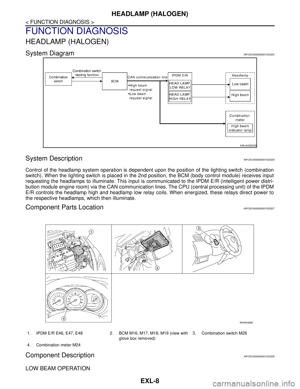
System DiagramINFOID:0000000001523225
System DescriptionINFOID:0000000001523226
Control of the headlamp system operation is dependent upon the position of the lighting switch (combination
switch). When the lighting switch is placed in the 2nd position, the BCM (body control module) receives input
requesting the headlamps to illuminate. This input is communicated to the IPDM E/R (intelligent power distri-
bution module engine room) via the CAN communication lines. The CPU (central processing unit) of the IPDM
E/R controls the headlamp high and headlamp low relay coils. When energized, these relays direct power to
the respective headlamps, which then illuminate.
Component Parts LocationINFOID:0000000001523227
Component DescriptionINFOID:0000000001523228
LOW BEAM OPERATION
AWLIA0002GB
1. IPDM E/R E46, E47, E48 2. BCM M16, M17, M18, M19 (view with
glove box removed)3. Combination switch M28
4. Combination meter M24
WKIA5469E
Page 3011 of 5883

EXL-10
< FUNCTION DIAGNOSIS >
HEADLAMP (XENON)
HEADLAMP (XENON)
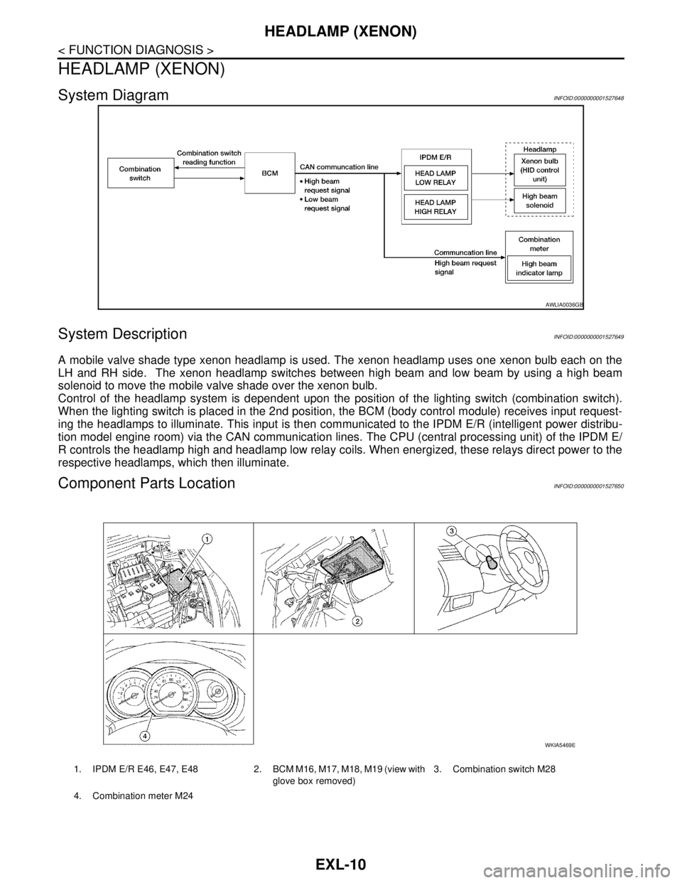
System DiagramINFOID:0000000001527648
System DescriptionINFOID:0000000001527649
A mobile valve shade type xenon headlamp is used. The xenon headlamp uses one xenon bulb each on the
LH and RH side. The xenon headlamp switches between high beam and low beam by using a high beam
solenoid to move the mobile valve shade over the xenon bulb.
Control of the headlamp system is dependent upon the position of the lighting switch (combination switch).
When the lighting switch is placed in the 2nd position, the BCM (body control module) receives input request-
ing the headlamps to illuminate. This input is then communicated to the IPDM E/R (intelligent power distribu-
tion model engine room) via the CAN communication lines. The CPU (central processing unit) of the IPDM E/
R controls the headlamp high and headlamp low relay coils. When energized, these relays direct power to the
respective headlamps, which then illuminate.
Component Parts LocationINFOID:0000000001527650
AWLIA0036GB
1. IPDM E/R E46, E47, E48 2. BCM M16, M17, M18, M19 (view with
glove box removed)3. Combination switch M28
4. Combination meter M24
WKIA5469E
Page 3018 of 5883

DAYTIME LIGHT SYSTEM
EXL-17
< FUNCTION DIAGNOSIS >
C
D
E
F
G
H
I
J
K
MA
B
EXL
N
O
P
DAYTIME LIGHT SYSTEM
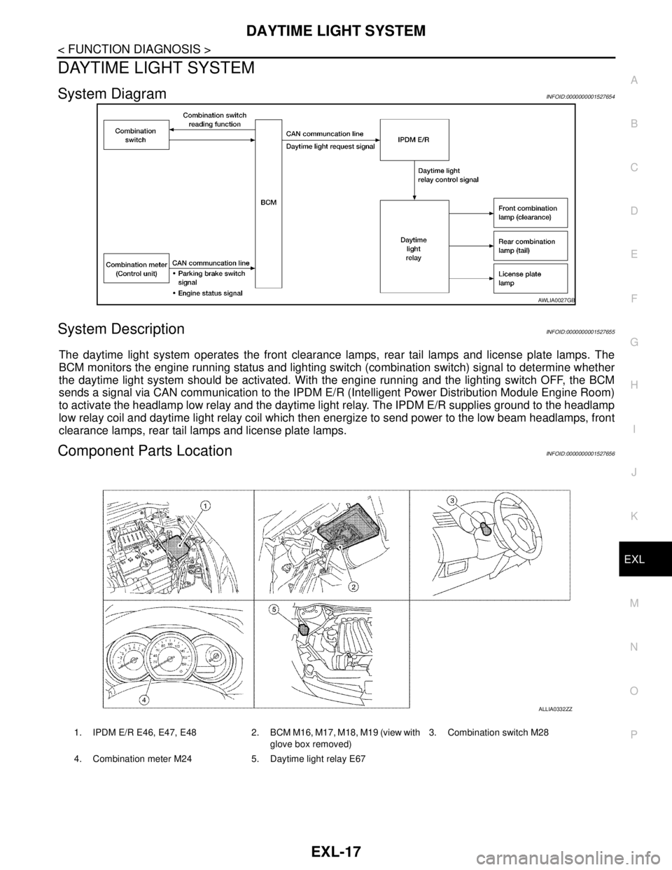
System DiagramINFOID:0000000001527654
System DescriptionINFOID:0000000001527655
The daytime light system operates the front clearance lamps, rear tail lamps and license plate lamps. The
BCM monitors the engine running status and lighting switch (combination switch) signal to determine whether
the daytime light system should be activated. With the engine running and the lighting switch OFF, the BCM
sends a signal via CAN communication to the IPDM E/R (Intelligent Power Distribution Module Engine Room)
to activate the headlamp low relay and the daytime light relay. The IPDM E/R supplies ground to the headlamp
low relay coil and daytime light relay coil which then energize to send power to the low beam headlamps, front
clearance lamps, rear tail lamps and license plate lamps.
Component Parts LocationINFOID:0000000001527656
AWLIA0027GB
1. IPDM E/R E46, E47, E48 2. BCM M16, M17, M18, M19 (view with
glove box removed)3. Combination switch M28
4. Combination meter M24 5. Daytime light relay E67
ALLIA0332ZZ
Page 3019 of 5883
EXL-18
< FUNCTION DIAGNOSIS >
DAYTIME LIGHT SYSTEM
Component Description
INFOID:0000000001527657
Part Description
BCM Monitors lighting switch position, engine running status and parking brake status to
determine if conditions are set for daytime light system operation.
Requests the IPDM E/R via CAN communication lines to ground the daytime light
relay coil.
IPDM E/RControls ground to the daytime light relay coil based on requests from the BCM (via
CAN communication lines).
Combination switch
(Lighting & turn signal switch)Refer to XX-XX, "*****"
.
Combination meterMonitors engine running status and forwards that information to the BCM via CAN
communication lines.
Page 3082 of 5883
HEADLAMP
EXL-81
< ON-VEHICLE MAINTENANCE >
C
D
E
F
G
H
I
J
K
MA
B
EXL
N
O
P
ON-VEHICLE MAINTENANCE
HEADLAMP
Aiming AdjustmentINFOID:0000000001529251
PREPARATION BEFORE ADJUSTING
Before performing aiming adjustment, check the following.
1. Keep all tires inflated to correct pressures.
2. Place vehicle on level surface.
3. Set that there is no-load in vehicle other than the driver (or equivalent weight placed in driver's position).
Coolant, engine oil filled up to correct level and full fuel tank.
LOW BEAM AND HIGH BEAM
1. Turn headlamp low beam ON.
2. Use adjusting screw to perform aiming adjustment.
ADJUSTMENT USING AN ADJUSTMENT SCREEN (LIGHT/DARK BORDERLINE)
1. Headlamp A. Inner and outer adjustment B. Adjusting screw
WKIA5417E