2007 NISSAN TIIDA fuse
[x] Cancel search: fusePage 5387 of 5883
![NISSAN TIIDA 2007 Service Repair Manual SYSTEM SYMPTOM
TM-441
< SYMPTOM DIAGNOSIS >[TYPE 2 (4AT: RE4F03B)]
C
E
F
G
H
I
J
K
L
MA
B
TM
N
O
P
.
3. Turn ignition switch OFF.
4. Check voltage between TCM connector terminals and ground.
OK or NG
NISSAN TIIDA 2007 Service Repair Manual SYSTEM SYMPTOM
TM-441
< SYMPTOM DIAGNOSIS >[TYPE 2 (4AT: RE4F03B)]
C
E
F
G
H
I
J
K
L
MA
B
TM
N
O
P
.
3. Turn ignition switch OFF.
4. Check voltage between TCM connector terminals and ground.
OK or NG](/manual-img/5/57395/w960_57395-5386.png)
SYSTEM SYMPTOM
TM-441
< SYMPTOM DIAGNOSIS >[TYPE 2 (4AT: RE4F03B)]
C
E
F
G
H
I
J
K
L
MA
B
TM
N
O
P
.
3. Turn ignition switch OFF.
4. Check voltage between TCM connector terminals and ground.
OK or NG
OK >> GO TO 4.
NG >> GO TO 3.
3.DETECT MALFUNCTIONING ITEM
Check the following.
Harness for short or open between ignition switch and TCM connector terminals 10, 19
Harness for short or open between battery and TCM connector terminal 28
10A fuse (No.13, located in the fuse block) and 10A fuse (No.49, located in the IPDM E/R)
Ignition switch.
OK or NG
OK >> GO TO 4.
NG >> Repair or replace damaged parts.
4.CHECK TCM GROUND CIRCUIT
1. Turn ignition switch OFF.
2. Disconnect TCM connector.
3. Check continuity between TCM connector terminals and ground.
OK or NG
OK >> GO TO 5.
NG >> Repair open circuit or short to ground or short to power
in harness or connectors.
5.DETECT MALFUNCTIONING ITEM
Check the following.
Harness for short or open between ignition switch and combination meter
Combination meter.
OK or NG
OK >> GO TO 6.
NG >> Repair or replace damaged parts.
6.CHECK SYMPTOM
Item Connector Terminal Judgement standard (Approx.)
TCM connectorE3110
Battery voltage 19
E32 28
SCIA2656E
Item Connector Terminal Judgement standard (Approx.)
TCM connectorE3110 0V
19 0V
E32 28 Battery voltage
SCIA2657E
Item Connector Terminal Continuity
TCM connector E32 25, 48 - Ground Yes
SCIA2671E
Page 5736 of 5883
WCS
POWER SUPPLY AND GROUND CIRCUIT
WCS-21
< COMPONENT DIAGNOSIS >
C
D
E
F
G
H
I
J
K
L
MB A
O
P
COMPONENT DIAGNOSIS
POWER SUPPLY AND GROUND CIRCUIT
COMBINATION METER
COMBINATION METER : Diagnosis ProcedureINFOID:0000000001728304
1.CHECK FUSES
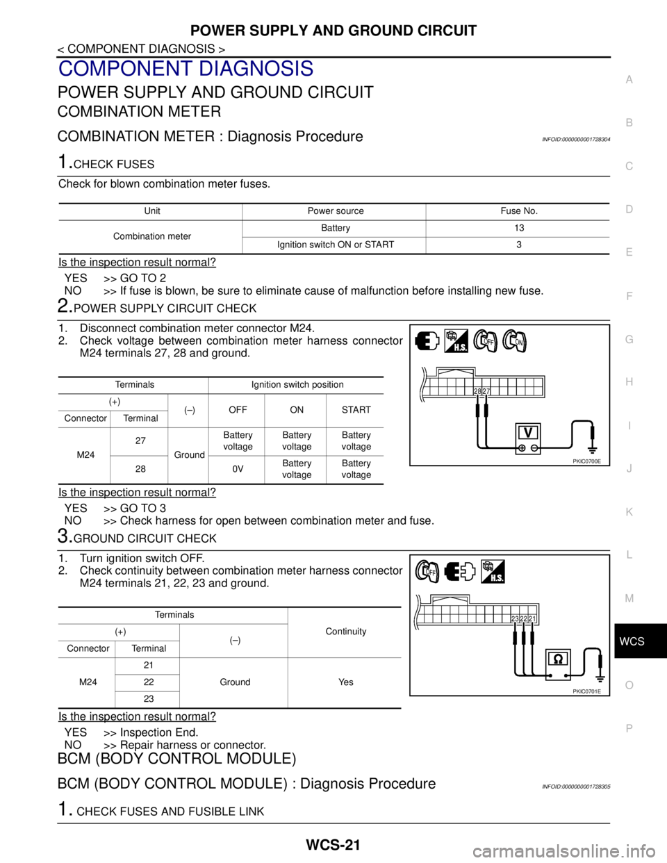
Check for blown combination meter fuses.
Is the inspection result normal?
YES >> GO TO 2
NO >> If fuse is blown, be sure to eliminate cause of malfunction before installing new fuse.
2.POWER SUPPLY CIRCUIT CHECK
1. Disconnect combination meter connector M24.
2. Check voltage between combination meter harness connector
M24 terminals 27, 28 and ground.
Is the inspection result normal?
YES >> GO TO 3
NO >> Check harness for open between combination meter and fuse.
3.GROUND CIRCUIT CHECK
1. Turn ignition switch OFF.
2. Check continuity between combination meter harness connector
M24 terminals 21, 22, 23 and ground.
Is the inspection result normal?
YES >> Inspection End.
NO >> Repair harness or connector.
BCM (BODY CONTROL MODULE)
BCM (BODY CONTROL MODULE) : Diagnosis ProcedureINFOID:0000000001728305
1. CHECK FUSES AND FUSIBLE LINK
Unit Power source Fuse No.
Combination meterBattery 13
Ignition switch ON or START 3
Terminals Ignition switch position
(+)
(–) OFF ON START
Connector Terminal
M2427
GroundBattery
voltageBattery
voltageBattery
voltage
28 0VBattery
voltageBattery
voltage
PKIC0700E
Te r m i n a l s
Continuity (+)
(–)
Connector Terminal
M2421
Ground Yes 22
23
PKIC0701E
Page 5737 of 5883
WCS-22
< COMPONENT DIAGNOSIS >
POWER SUPPLY AND GROUND CIRCUIT
Check that the following fuses and fusible link are not fusing.
Is the fuse fusing?
YES >> Replace the blown fuse or fusible link after repairing the affected circuit if a fuse or fusible link is
blown.
NO >> GO TO 2.
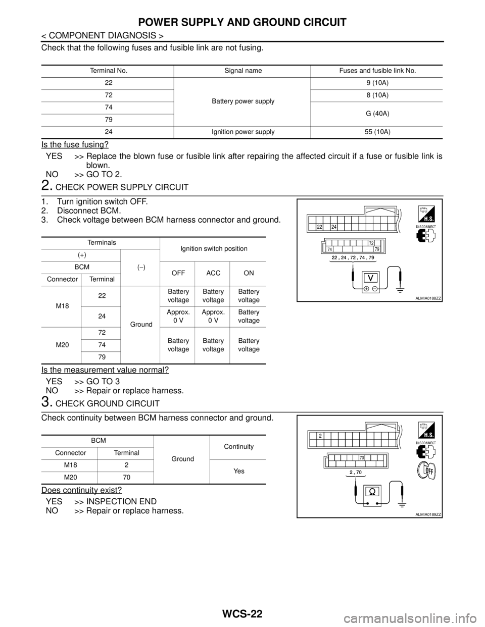
2. CHECK POWER SUPPLY CIRCUIT
1. Turn ignition switch OFF.
2. Disconnect BCM.
3. Check voltage between BCM harness connector and ground.
Is the measurement value normal?
YES >> GO TO 3
NO >> Repair or replace harness.
3. CHECK GROUND CIRCUIT
Check continuity between BCM harness connector and ground.
Does continuity exist?
YES >> INSPECTION END
NO >> Repair or replace harness.
Terminal No. Signal name Fuses and fusible link No.
22
Battery power supply9 (10A)
728 (10A)
74
G (40A)
79
24 Ignition power supply 55 (10A)
Te r m i n a l s
Ignition switch position
(+)
(−) BCM
OFF ACC ON
Connector Terminal
M1822
GroundBattery
voltageBattery
voltageBattery
voltage
24Approx.
0 VApprox.
0 VBattery
voltage
M2072
Battery
voltageBattery
voltageBattery
voltage 74
79
ALMIA0188ZZ
BCM
GroundContinuity
Connector Terminal
M18 2
Ye s
M20 70
ALMIA0189ZZ
Page 5741 of 5883
WCS-26
< COMPONENT DIAGNOSIS >
KEY SWITCH SIGNAL CIRCUIT (WITH INTELLIGENT KEY)
KEY SWITCH SIGNAL CIRCUIT (WITH INTELLIGENT KEY)
DescriptionINFOID:0000000001722936
Transmits a key switch signal to the BCM.
Component Function CheckINFOID:0000000001722937
1.CHECK BCM INPUT SIGNAL
Select “DATA MONITOR” for “BCM” and check the “KEY IN SW” monitor value.
>> Inspection End.
Diagnosis ProcedureINFOID:0000000001722938
1.CHECK FUSE
Check if the key switch and ignition knob switch 10A fuse (No. 31, located in the fuse and relay box) is blown.
Is the fuse blown?
YES >> Be sure to repair the cause of malfunction before installing new fuse.
NO >> GO TO 2
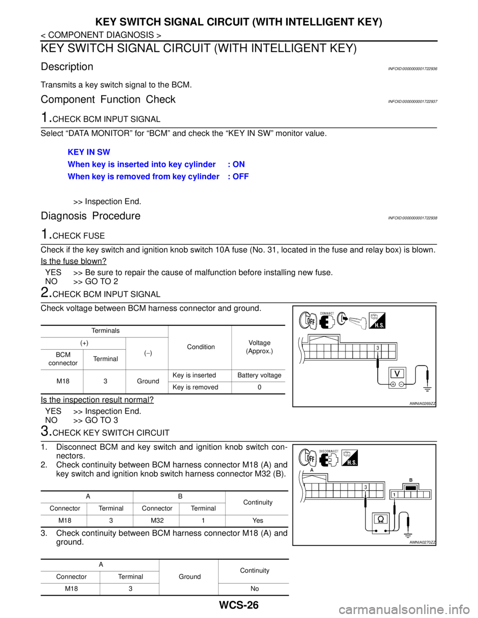
2.CHECK BCM INPUT SIGNAL
Check voltage between BCM harness connector and ground.
Is the inspection result normal?
YES >> Inspection End.
NO >> GO TO 3
3.CHECK KEY SWITCH CIRCUIT
1. Disconnect BCM and key switch and ignition knob switch con-
nectors.
2. Check continuity between BCM harness connector M18 (A) and
key switch and ignition knob switch harness connector M32 (B).
3. Check continuity between BCM harness connector M18 (A) and
ground.KEY IN SW
When key is inserted into key cylinder : ON
When key is removed from key cylinder : OFF
Te r m i n a l s
ConditionVo l ta g e
(Approx.) (+)
(−)
BCM
connectorTe r m i n a l
M18 3 GroundKey is inserted Battery voltage
Key is removed 0
AWNIA0269ZZ
AB
Continuity
Connector Terminal Connector Terminal
M183M321 Yes
A
GroundContinuity
Connector Terminal
M18 3 No
AWNIA0270ZZ
Page 5743 of 5883
WCS-28
< COMPONENT DIAGNOSIS >
KEY SWITCH SIGNAL CIRCUIT (WITHOUT INTELLIGENT KEY)
KEY SWITCH SIGNAL CIRCUIT (WITHOUT INTELLIGENT KEY)
DescriptionINFOID:0000000001722940
Transmits a key switch signal to the BCM.
Component Function CheckINFOID:0000000001722941
1.CHECK BCM INPUT SIGNAL
Select “DATA MONITOR” for “BCM” and check the “KEY IN SW” monitor value.
>> Inspection End.
Diagnosis ProcedureINFOID:0000000001722942
1.CHECK FUSE
Check if the key switch and key lock solenoid 10A fuse [No. 14, located in the fuse block (J/B)] is blown.
Is the fuse blown?
YES >> Be sure to repair the cause of malfunction before installing new fuse.
NO >> GO TO 2
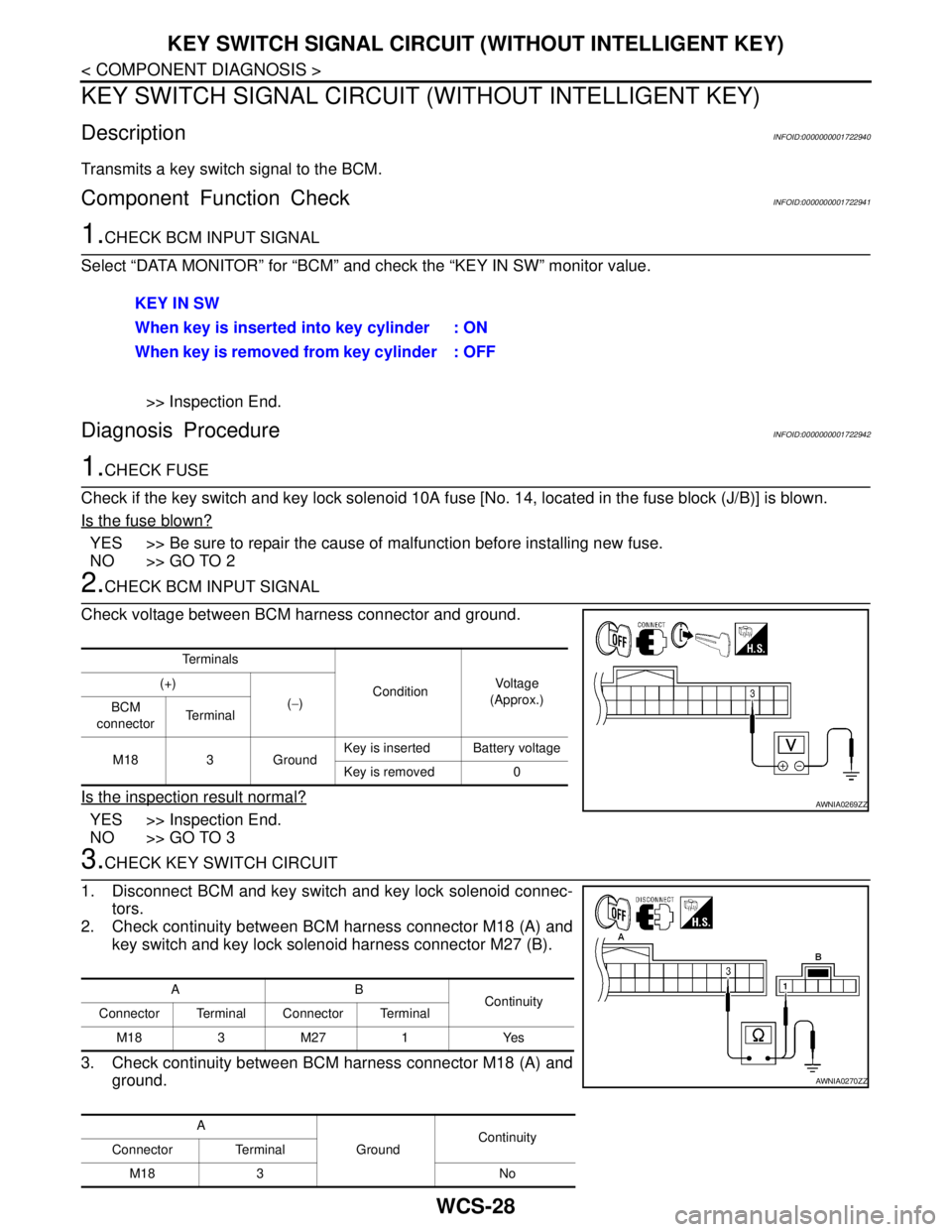
2.CHECK BCM INPUT SIGNAL
Check voltage between BCM harness connector and ground.
Is the inspection result normal?
YES >> Inspection End.
NO >> GO TO 3
3.CHECK KEY SWITCH CIRCUIT
1. Disconnect BCM and key switch and key lock solenoid connec-
tors.
2. Check continuity between BCM harness connector M18 (A) and
key switch and key lock solenoid harness connector M27 (B).
3. Check continuity between BCM harness connector M18 (A) and
ground.KEY IN SW
When key is inserted into key cylinder : ON
When key is removed from key cylinder : OFF
Te r m i n a l s
ConditionVo l ta g e
(Approx.) (+)
(−)
BCM
connectorTe r m i n a l
M18 3 GroundKey is inserted Battery voltage
Key is removed 0
AWNIA0269ZZ
AB
Continuity
Connector Terminal Connector Terminal
M183M271 Yes
A
GroundContinuity
Connector Terminal
M18 3 No
AWNIA0270ZZ
Page 5770 of 5883
WCS
COMBINATION METER
WCS-55
< ECU DIAGNOSIS >
C
D
E
F
G
H
I
J
K
L
MB A
O
P
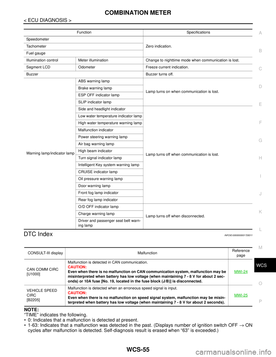
DTC IndexINFOID:0000000001728311
NOTE:
“TIME” indicates the following.
0: Indicates that a malfunction is detected at present.
1-63: Indicates that a malfunction was detected in the past. (Displays number of ignition switch OFF → ON
cycles after malfunction is detected. Self-diagnosis result is erased when “63” is exceeded.)
Function Specifications
Speedometer
Zero indication. Tachometer
Fuel gauge
Illumination control Meter illumination Change to nighttime mode when communication is lost.
Segment LCD Odometer Freeze current indication.
Buzzer Buzzer turns off.
Warning lamp/indicator lampABS warning lamp
Lamp turns on when communication is lost. Brake warning lamp
ESP OFF indicator lamp
SLIP indicator lamp
Side and headlight indicator
Lamp turns off when communication is lost. Low water temperature indicator lamp
High water temperature warning lamp
Malfunction indicator
Power steering warning lamp
Air bag warning lamp
High beam indicator
Turn signal indicator lamp
Intelligent Key system warning lamp
CRUISE indicator lamp
Oil pressure warning lamp
Door warning lamp
Front fog lamp indicator
Rear fog lamp indicator
O/D OFF indicator lamp
Lamp turns off when disconnected. Charge warning lamp
Driver and passenger seat belt warn-
ing lamp
CONSULT-III display MalfunctionReference
page
CAN COMM CIRC
[U1000]Malfunction is detected in CAN communication.
CAUTION:
Even when there is no malfunction on CAN communication system, malfunction may be
misinterpreted when battery has low voltage (when maintaining 7 - 8 V for about 2 sec-
onds) or 10A fuse [No. 19, located in the fuse block (J/B)] is disconnected.MWI-24
VEHICLE SPEED
CIRC
[B2205]Malfunction is detected when an erroneous speed signal is input.
CAUTION:
Even when there is no malfunction on speed signal system, malfunction may be misin-
terpreted when battery has low voltage (when maintaining 7 - 8 V for about 2 seconds). MWI-25
Page 5803 of 5883

WW-1
DRIVER CONTROLS
C
D
E
F
G
H
I
J
K
M
SECTION WW
A
B
WW
N
O
P
CONTENTS
WIPER & WASHER
BASIC INSPECTION ....................................3
DIAGNOSIS AND REPAIR WORKFLOW ..........3
Work Flow .................................................................3
FUNCTION DIAGNOSIS ...............................4
FRONT WIPER AND WASHER SYSTEM ..........4
System Diagram ........................................................4
System Description ...................................................4
Component Parts Location ........................................7
Component Description ............................................8
REAR WIPER AND WASHER SYSTEM ............9
System Diagram ........................................................9
System Description ...................................................9
Component Parts Location ......................................11
Component Description ..........................................11
HEADLAMP WASHER SYSTEM .......................12
System Diagram ......................................................12
System Description .................................................12
Component Parts Location ......................................13
Component Description ..........................................13
DIAGNOSIS SYSTEM (BCM) ............................14
COMMON ITEM .........................................................14
COMMON ITEM : CONSULT-III Function (BCM -
COMMON ITEM) .....................................................
14
WIPER .......................................................................14
WIPER : CONSULT-III Function (BCM - WIPER) ....14
DIAGNOSIS SYSTEM (IPDM E/R) .....................16
Diagnosis Description .............................................16
CONSULT - III Function (IPDM E/R) .......................16
COMPONENT DIAGNOSIS .........................17
WIPER AND WASHER FUSE, FUSIBLE LINK
....
17
Description ..............................................................17
Diagnosis Procedure ...............................................17
FRONT WIPER MOTOR LO CIRCUIT ..............18
Component Function Check ....................................18
Diagnosis Procedure ...............................................18
FRONT WIPER MOTOR HI CIRCUIT ...............20
Component Function Check ....................................20
Diagnosis Procedure ...............................................20
FRONT WIPER AUTO STOP SIGNAL CIR-
CUIT ..................................................................
22
Component Function Check ....................................22
Diagnosis Procedure ...............................................22
FRONT WIPER MOTOR GROUND CIRCUIT ...24
Diagnosis Procedure ...............................................24
WASHER SWITCH ............................................25
Description ...............................................................25
Component Inspection .............................................25
LIGHT & RAIN SENSOR ..................................27
Description ...............................................................27
Diagnosis Procedure ...............................................27
REAR WIPER MOTOR CIRCUIT ......................28
Component Function Check ....................................28
Diagnosis Procedure ...............................................28
REAR WIPER AUTO STOP SIGNAL CIRCUIT
...
30
Component Function Check ....................................30
Diagnosis Procedure ...............................................30
HEADLAMP WASHER RELAY ........................32
Component Inspection .............................................32
HEADLAMP WASHER CIRCUIT ......................33
Component Function Check ....................................33
Diagnosis Procedure ...............................................33
FRONT WIPER AND WASHER SYSTEM ........36
Page 5819 of 5883
WIPER AND WASHER FUSE, FUSIBLE LINK
WW-17
< COMPONENT DIAGNOSIS >
C
D
E
F
G
H
I
J
K
MA
B
WW
N
O
P
COMPONENT DIAGNOSIS
WIPER AND WASHER FUSE, FUSIBLE LINK
DescriptionINFOID:0000000001366608
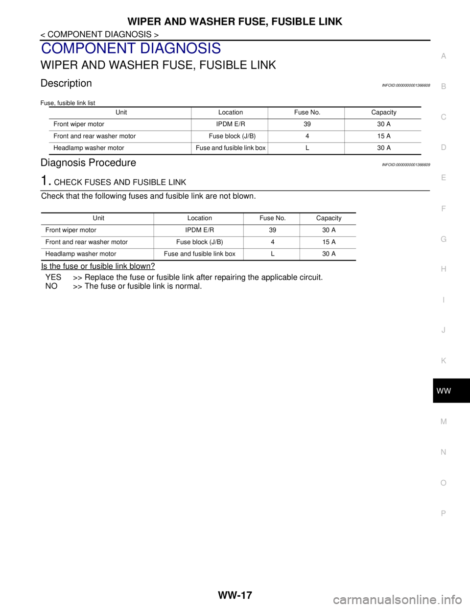
Fuse, fusible link list
Diagnosis ProcedureINFOID:0000000001366609
1. CHECK FUSES AND FUSIBLE LINK
Check that the following fuses and fusible link are not blown.
Is the fuse or fusible link blown?
YES >> Replace the fuse or fusible link after repairing the applicable circuit.
NO >> The fuse or fusible link is normal.
Unit Location Fuse No. Capacity
Front wiper motor IPDM E/R 39 30 A
Front and rear washer motor Fuse block (J/B) 4 15 A
Headlamp washer motor Fuse and fusible link box L 30 A
Unit Location Fuse No. Capacity
Front wiper motor IPDM E/R 39 30 A
Front and rear washer motor Fuse block (J/B) 4 15 A
Headlamp washer motor Fuse and fusible link box L 30 A