2007 NISSAN TIIDA recommended oil
[x] Cancel search: recommended oilPage 2843 of 5883
![NISSAN TIIDA 2007 Service Repair Manual EM-196
< ON-VEHICLE REPAIR >[MR18DE]
OIL SEAL
Drive belt; Refer to EM-142, "Component".
Crankshaft pulley; Refer to EM-176, "
Component".
2. Remove front oil seal using a suitable tool.
CAUTION:
B NISSAN TIIDA 2007 Service Repair Manual EM-196
< ON-VEHICLE REPAIR >[MR18DE]
OIL SEAL
Drive belt; Refer to EM-142, "Component".
Crankshaft pulley; Refer to EM-176, "
Component".
2. Remove front oil seal using a suitable tool.
CAUTION:
B](/manual-img/5/57395/w960_57395-2842.png)
EM-196
< ON-VEHICLE REPAIR >[MR18DE]
OIL SEAL
Drive belt; Refer to EM-142, "Component".
Crankshaft pulley; Refer to EM-176, "
Component".
2. Remove front oil seal using a suitable tool.
CAUTION:
Be careful not to damage front cover and crankshaft.
INSTALLATION
1. Apply new engine oil to new front oil seal joint surface and seal lip.
2. Install front oil seal so that each seal lip is oriented as shown in
the figure.
Install front oil seal (2) using a suitable tool with outer diameter
57 mm (2.24 in) and inner diameter 45 mm (1.77 in) (A) to the
dimension as shown.
CAUTION:
Be careful not to damage front cover and crankshaft.
Press-fit oil seal straight to avoid causing burrs or tilt-
ing.
Do not touch grease applied on oil seal lip.
3. Installation of the remaining components is in the reverse order of removal.
Removal and Installation of Rear Oil SealINFOID:0000000001337802
REMOVAL
1. Remove transaxle assembly. Refer to TM-681, "Removal and Installation".
2. Remove clutch cover and clutch disk. Refer to CL-13, "
Removal and Installation".
3. Remove flywheel. Refer to EM-211, "
Component".
4. Remove rear oil seal with a suitable tool.
CAUTION:
Be careful not to damage crankshaft and cylinder block.
INSTALLATION
1. Apply the liquid gasket lightly to entire outside area of new rear oil seal.
Use Genuine Silicone RTV Sealant or equivalent. Refer to GI-27, "
Recommended Chemical Prod-
ucts and Sealants".
A : Dust seal lip
B : Oil seal lip
: Engine outside
: Engine inside
PBIC3485J
Within 0.3 mm (0.012 in) toward engine front
Within 0.5 mm (0.020 in) toward engine rear
PBIC3729E
Page 2862 of 5883
![NISSAN TIIDA 2007 Service Repair Manual ENGINE UNIT
EM-215
< DISASSEMBLY AND ASSEMBLY >[MR18DE]
C
D
E
F
G
H
I
J
K
L
MA
EM
N
P O
2. Install water drain plug (1) to cylinder block.
Apply liquid gasket to the drain plug thread.
Use Genuine S NISSAN TIIDA 2007 Service Repair Manual ENGINE UNIT
EM-215
< DISASSEMBLY AND ASSEMBLY >[MR18DE]
C
D
E
F
G
H
I
J
K
L
MA
EM
N
P O
2. Install water drain plug (1) to cylinder block.
Apply liquid gasket to the drain plug thread.
Use Genuine S](/manual-img/5/57395/w960_57395-2861.png)
ENGINE UNIT
EM-215
< DISASSEMBLY AND ASSEMBLY >[MR18DE]
C
D
E
F
G
H
I
J
K
L
MA
EM
N
P O
2. Install water drain plug (1) to cylinder block.
Apply liquid gasket to the drain plug thread.
Use Genuine Silicone RTV Sealant or equivalent. Refer to
GI-27, "
Recommended Chemical Products and Sealants".
3. Remove dust, dirt, and engine oil on the bearing mating sur-
faces of cylinder block and main bearing cap.
4. Install thrust bearings to the both sides of the No. 3 journal hous-
ing (B) on cylinder block.
Install thrust bearings with the oil groove (A) facing crankshaft
arm (outside).
5. Install the main bearings paying attention to the direction.
CAUTION:
Before installing main bearings, apply new engine oil to the bearing surface (inside). Do not
apply new engine oil to the back surface, but thoroughly clean it.
When installing, align main bearing to the center position of cylinder block and main bearing
cap.
The difference (A) between main bearing upper (1) and
main bearing lower (3) should be 0.85 mm (0.033 in) or
less when installing.
Ensure the oil holes on cylinder block and oil holes (A) on
the main bearings (1) are aligned.
6. Install signal plate to crankshaft if removed.
7. Set the signal plate with the flange facing toward the counter weight side (engine front side) to the crank-
shaft rear surface.
8. Apply new engine oil to threads and seat surfaces of bolts.
: Engine front
9.8 N·m (1.0 kg-m, 87 in-lb)
PBIC3228J
: Engine front
PBIC3258J
2 : Cylinder block
4 : Main bearing cap
PBIC3237J
PBIC3236J
Page 2929 of 5883
![NISSAN TIIDA 2007 Service Repair Manual EM-282
< ON-VEHICLE REPAIR >[K9K]
INJECTION TUBE AND FUEL INJECTOR
6. Remove fuel hose shield.
7. Disconnect fuel feed hose.
8. Remove high pressure pipes protection cover (upper).
9. Remove the neck NISSAN TIIDA 2007 Service Repair Manual EM-282
< ON-VEHICLE REPAIR >[K9K]
INJECTION TUBE AND FUEL INJECTOR
6. Remove fuel hose shield.
7. Disconnect fuel feed hose.
8. Remove high pressure pipes protection cover (upper).
9. Remove the neck](/manual-img/5/57395/w960_57395-2928.png)
EM-282
< ON-VEHICLE REPAIR >[K9K]
INJECTION TUBE AND FUEL INJECTOR
6. Remove fuel hose shield.
7. Disconnect fuel feed hose.
8. Remove high pressure pipes protection cover (upper).
9. Remove the neck located on the fuel rail.
NOTE:
Undo the nut on the pump side or the injector side, then the nut located on the rail side. Undo the
nuts for each pipe in turn. Move the nut along the pipe keeping the olive in contact with the taper.
10. Remove all the injection tubes.
11. Plug all the holes in the injection circuit.
12. Remove fuel rail.
13. Disconnect fuel return pipe.
14. Remove retaining clip and disconnect the diesel return pipe on
the injector.
15. Plug all the holes of the injection circuit.
16. Disconnect the injector harness connector (1).
17. Remove the injector bracket (2).
18. Remove the injector.
19. Pull off the flame shield washer.
20. Disconnect the fuel pressure sensor.
21. Remove the high pressure pipes protection cover (lower).
INSTALLATION
CAUTION:
All the injection tubes removed must be systematically replaced.
1. Clean the injector sockets and the injector bodies, as well as their brackets using a lint-free cloth (use the
wipes recommended for this purpose, dipped in clean solvent.
2. Dry off using a different new wipe.
3. Replace the flame shield washer with a new one.
4. Position the injector.
5. Tighten the mounting bracket bolts.
6. Install injection tubes with new one.
7. Finger tighten the nuts.
8. Before fitting the new injection tubes, lightly lubricate the nut threads with the oil from the sachet provided
in the new parts kit.
NOTE:
Fit the pump/rail pipe before the rail/injector tubes.
9. Fit the pump-rail injection tube as follows:
Remove the protective plugs from the high pressure pump outlet, the high pressure rail inlet and the
pipe.
E1BIA0049ZZ
MBIB9030E
: 30.0 N·m (3.1 kg-m, 22 ft-lb)
Page 3182 of 5883
FSU-6
< ON-VEHICLE MAINTENANCE >
FRONT SUSPENSION ASSEMBLY
ON-VEHICLE MAINTENANCE
FRONT SUSPENSION ASSEMBLY
On-Vehicle Inspection and ServiceINFOID:0000000001716890
Make sure the mounting conditions (looseness, back lash) of each component and component conditions
(wear, damage) are normal.
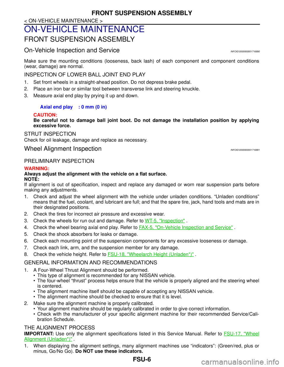
INSPECTION OF LOWER BALL JOINT END PLAY
1. Set front wheels in a straight-ahead position. Do not depress brake pedal.
2. Place an iron bar or similar tool between transverse link and steering knuckle.
3. Measure axial end play by prying it up and down.
CAUTION:
Be careful not to damage ball joint boot. Do not damage the installation position by applying
excessive force.
STRUT INSPECTION
Check for oil leakage, damage and replace as necessary.
Wheel Alignment InspectionINFOID:0000000001716891
PRELIMINARY INSPECTION
WARNING:
Always adjust the alignment with the vehicle on a flat surface.
NOTE:
If alignment is out of specification, inspect and replace any damaged or worn rear suspension parts before
making any adjustments.
1. Check and adjust the wheel alignment with the vehicle under unladen conditions. “Unladen conditions”
means that the fuel, coolant, and lubricant are full; and that the spare tire, jack, hand tools and mats are in
their designated positions.
2. Check the tires for incorrect air pressure and excessive wear.
3. Check the wheels for run out and damage. Refer to WT-5, "
Inspection" .
4. Check the wheel bearing axial end play. Refer to FA X - 5 , "
On-Vehicle Inspection and Service" .
5. Check the shock absorbers for leaks or damage.
6. Check each mounting point of the suspension components for any excessive looseness or damage.
7. Check each link, arm, and the suspension member for any damage.
8. Check the vehicle height. Refer to FSU-18, "
Wheelarch Height (Unladen*)" .
GENERAL INFORMATION AND RECOMMENDATIONS
1. A Four-Wheel Thrust Alignment should be performed.
This type of alignment is recommended for any NISSAN vehicle.
The four-wheel “thrust” process helps ensure that the vehicle is properly aligned and the steering wheel
is centered.
The alignment machine itself should be capable of accepting any NISSAN vehicle.
The alignment machine should be checked to ensure that it is level.
2. Make sure the alignment machine is properly calibrated.
Your alignment machine should be regularly calibrated in order to give correct information.
Check with the manufacturer of your specific alignment machine for their recommended Service/Cali-
bration Schedule.
THE ALIGNMENT PROCESS
IMPORTANT: Use only the alignment specifications listed in this Service Manual. Refer to FSU-17, "Wheel
Alignment (Unladen*)" .
1. When displaying the alignment settings, many alignment machines use “indicators”: (Green/red, plus or
minus, Go/No Go). Do NOT use these indicators. Axial end play : 0 mm (0 in)
Page 3195 of 5883
GI-1
GENERAL INFORMATION
C
D
E
F
G
H
I
J
K
L
MB
GI
SECTION GI
N
O
P
CONTENTS
GENERAL INFORMATION
HOW TO USE THIS MANUAL ......................3
HOW TO USE THIS MANUAL ............................3
Description ................................................................3
Terms ........................................................................3
Units ..........................................................................3
Contents ....................................................................3
Relation between Illustrations and Descriptions .......4
Component ................................................................4
How to Follow Trouble Diagnosis ..............................5
How to Read Wiring Diagram ....................................9
Abbreviations ..........................................................16
HOW TO FOLLOW TROUBLE DIAGNOSES ....18
Description ..............................................................18
How to Follow Test Groups in Trouble Diagnosis ....18
Key to Symbols Signifying Measurements or Pro-
cedures ...................................................................
19
HOW TO READ WIRING DIAGRAMS ...............21
Connector symbols .................................................21
Sample/wiring diagram -example- ...........................22
Description ..............................................................23
ABBREVIATIONS ..............................................25
Abbreviation List ......................................................25
TIGHTENING TORQUE OF STANDARD
BOLTS ................................................................
26
Tightening Torque Table .........................................26
RECOMMENDED CHEMICAL PRODUCTS
AND SEALANTS ................................................
27
Recommended Chemical Products and Sealants ....27
TERMINOLOGY .................................................28
SAE J1930 Terminology List ...................................28
FEATURES OF NEW MODEL .....................32
IDENTIFICATION INFORMATION .....................32
Model Variation .......................................................32
Dimensions ..............................................................41
Wheels & Tires ........................................................42
PRECAUTION ..............................................43
PRECAUTIONS .................................................43
Description ...............................................................43
Precaution for Supplemental Restraint System
(SRS) "AIR BAG" and "SEAT BELT PRE-TEN-
SIONER" .................................................................
43
Precaution Necessary for Steering Wheel Rota-
tion After Battery Disconnect ...................................
43
General Precaution ..................................................44
Precaution for Three Way Catalyst ..........................45
Precaution for Fuel (Unleaded Regular Gasoline
Recommended) .......................................................
45
Precaution for Multiport Fuel Injection System or
Engine Control System ............................................
46
Precaution for Hoses ...............................................46
Precaution for Engine Oils .......................................47
Precaution for Air Conditioning ................................47
LIFTING POINT .................................................48
Special Service Tool ................................................48
Garage Jack and Safety Stand and 2-Pole Lift .......48
Board-On Lift ...........................................................49
TOW TRUCK TOWING .....................................50
Tow Truck Towing ...................................................50
Vehicle Recovery (Freeing a Stuck Vehicle) ...........50
BASIC INSPECTION ...................................51
SERVICE INFORMATION FOR ELECTRICAL
INCIDENT ..........................................................
51
Work Flow ................................................................51
Control Units and Electrical Parts ............................51
How to Check Terminal ...........................................52
Intermittent Incident .................................................55
Circuit Inspection .....................................................58
CONSULT-III CHECKING SYSTEM .................63
Page 3239 of 5883
PRECAUTIONS
GI-45
< PRECAUTION >
C
D
E
F
G
H
I
J
K
L
MB
GI
N
O
P
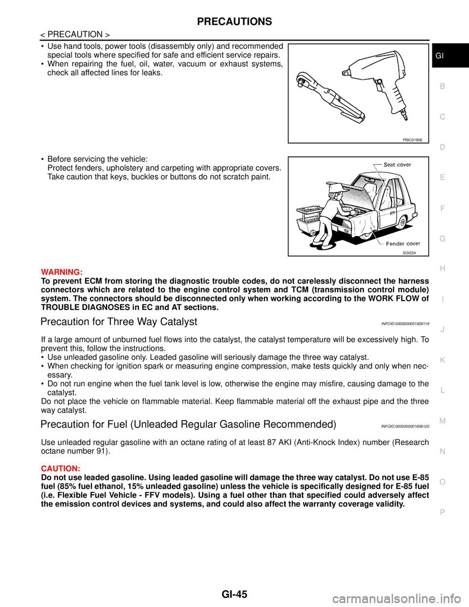
Use hand tools, power tools (disassembly only) and recommended
special tools where specified for safe and efficient service repairs.
When repairing the fuel, oil, water, vacuum or exhaust systems,
check all affected lines for leaks.
Before servicing the vehicle:
Protect fenders, upholstery and carpeting with appropriate covers.
Take caution that keys, buckles or buttons do not scratch paint.
WARNING:
To prevent ECM from storing the diagnostic trouble codes, do not carelessly disconnect the harness
connectors which are related to the engine control system and TCM (transmission control module)
system. The connectors should be disconnected only when working according to the WORK FLOW of
TROUBLE DIAGNOSES in EC and AT sections.
Precaution for Three Way CatalystINFOID:0000000001606119
If a large amount of unburned fuel flows into the catalyst, the catalyst temperature will be excessively high. To
prevent this, follow the instructions.
Use unleaded gasoline only. Leaded gasoline will seriously damage the three way catalyst.
When checking for ignition spark or measuring engine compression, make tests quickly and only when nec-
essary.
Do not run engine when the fuel tank level is low, otherwise the engine may misfire, causing damage to the
catalyst.
Do not place the vehicle on flammable material. Keep flammable material off the exhaust pipe and the three
way catalyst.
Precaution for Fuel (Unleaded Regular Gasoline Recommended)INFOID:0000000001606120
Use unleaded regular gasoline with an octane rating of at least 87 AKI (Anti-Knock Index) number (Research
octane number 91).
CAUTION:
Do not use leaded gasoline. Using leaded gasoline will damage the three way catalyst. Do not use E-85
fuel (85% fuel ethanol, 15% unleaded gasoline) unless the vehicle is specifically designed for E-85 fuel
(i.e. Flexible Fuel Vehicle - FFV models). Using a fuel other than that specified could adversely affect
the emission control devices and systems, and could also affect the warranty coverage validity.
PBIC0190E
SGI234
Page 3291 of 5883
PRECAUTIONS
HA-9
< PRECAUTION >
C
D
E
F
G
H
J
K
L
MA
B
HA
N
O
P
When the compressor is removed, store it in the same position as it is when mounted on the car.
When replacing or repairing compressor, follow “Maintenance of Oil Quantity in Compressor”
exactly. Refer to HA-19, "
Maintenance of Oil Quantity in Compressor".
Keep friction surfaces between clutch and pulley clean. If the surface is contaminated, with oil, wipe
it off by using a clean waste cloth moistened with thinner.
After compressor service operation, turn the compressor shaft by hand more than five turns in both
directions. This will equally distribute oil inside the compressor. After the compressor is installed,
let the engine idle and operate the compressor for one hour.
After replacing the compressor magnet clutch, apply voltage to the new one and check for usual
operation.
Precaution for Service EquipmentINFOID:0000000001396434
RECOVERY/RECYCLING EQUIPMENT
Be certain to follow the manufacturer’s instructions for machine operation and machine maintenance. Never
introduce any refrigerant other than that specified into the machine.
ELECTRONIC LEAK DETECTOR
Be certain to follow the manufacturer’s instructions for tester operation and tester maintenance.
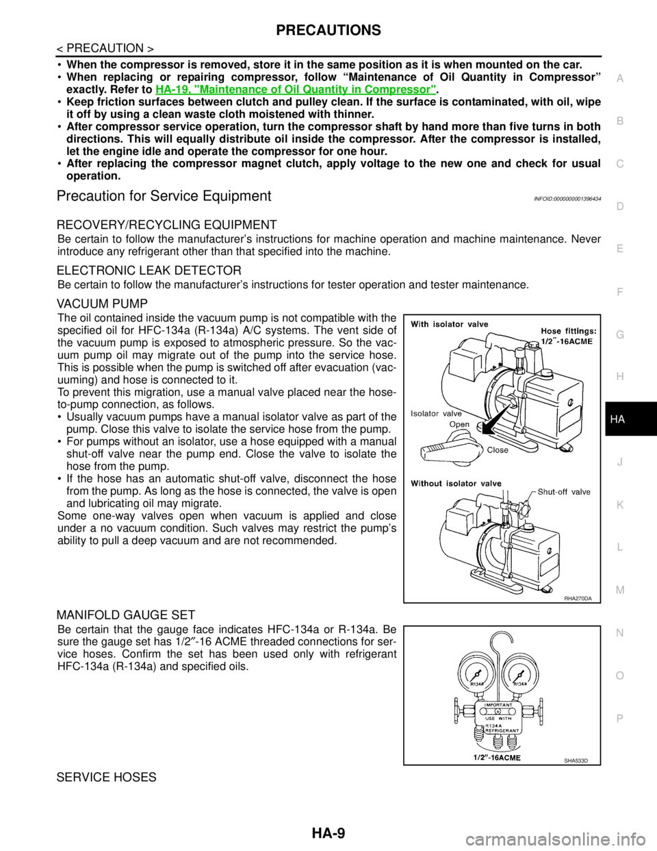
VACUUM PUMP
The oil contained inside the vacuum pump is not compatible with the
specified oil for HFC-134a (R-134a) A/C systems. The vent side of
the vacuum pump is exposed to atmospheric pressure. So the vac-
uum pump oil may migrate out of the pump into the service hose.
This is possible when the pump is switched off after evacuation (vac-
uuming) and hose is connected to it.
To prevent this migration, use a manual valve placed near the hose-
to-pump connection, as follows.
Usually vacuum pumps have a manual isolator valve as part of the
pump. Close this valve to isolate the service hose from the pump.
For pumps without an isolator, use a hose equipped with a manual
shut-off valve near the pump end. Close the valve to isolate the
hose from the pump.
If the hose has an automatic shut-off valve, disconnect the hose
from the pump. As long as the hose is connected, the valve is open
and lubricating oil may migrate.
Some one-way valves open when vacuum is applied and close
under a no vacuum condition. Such valves may restrict the pump’s
ability to pull a deep vacuum and are not recommended.
MANIFOLD GAUGE SET
Be certain that the gauge face indicates HFC-134a or R-134a. Be
sure the gauge set has 1/2″-16 ACME threaded connections for ser-
vice hoses. Confirm the set has been used only with refrigerant
HFC-134a (R-134a) and specified oils.
SERVICE HOSES
RHA270DA
SHA533D
Page 3292 of 5883
HA-10
< PRECAUTION >
PRECAUTIONS
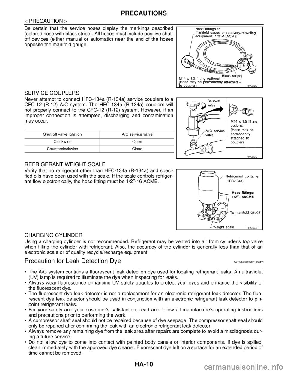
Be certain that the service hoses display the markings described
(colored hose with black stripe). All hoses must include positive shut-
off devices (either manual or automatic) near the end of the hoses
opposite the manifold gauge.
SERVICE COUPLERS
Never attempt to connect HFC-134a (R-134a) service couplers to a
CFC-12 (R-12) A/C system. The HFC-134a (R-134a) couplers will
not properly connect to the CFC-12 (R-12) system. However, if an
improper connection is attempted, discharging and contamination
may occur.
REFRIGERANT WEIGHT SCALE
Verify that no refrigerant other than HFC-134a (R-134a) and speci-
fied oils have been used with the scale. If the scale controls refriger-
ant flow electronically, the hose fitting must be 1/2″-16 ACME.
CHARGING CYLINDER
Using a charging cylinder is not recommended. Refrigerant may be vented into air from cylinder’s top valve
when filling the cylinder with refrigerant. Also, the accuracy of the cylinder is generally less than that of an
electronic scale or of quality recycle/recharge equipment.
Precaution for Leak Detection DyeINFOID:0000000001396435
The A/C system contains a fluorescent leak detection dye used for locating refrigerant leaks. An ultraviolet
(UV) lamp is required to illuminate the dye when inspecting for leaks.
Always wear fluorescence enhancing UV safety goggles to protect your eyes and enhance the visibility of
the fluorescent dye.
The fluorescent dye leak detector is not a replacement for an electronic refrigerant leak detector. The fluo-
rescent dye leak detector should be used in conjunction with an electronic refrigerant leak detector to pin-
point refrigerant leaks.
For your safety and your customer’s satisfaction, read and follow all manufacture’s operating instructions
and precautions prior to performing the work.
A compressor shaft seal should not be repaired because of dye seepage. The compressor shaft seal should
only be repaired after confirming the leak with an electronic refrigerant leak detector.
Always remove any remaining dye from the leak area after repairs are complete to avoid a misdiagnosis dur-
ing a future service.
Do not allow dye to come into contact with painted body panels or interior components. If dye is spilled,
clean immediately with the approved dye cleaner. Fluorescent dye left on a surface for an extended period of
time cannot be removed.
RHA272D
Shut-off valve rotation A/C service valve
Clockwise Open
Counterclockwise Close
RHA273D
RHA274D