2007 NISSAN TIIDA open hood
[x] Cancel search: open hoodPage 3118 of 5883

EXT-14
< ON-VEHICLE REPAIR >
FRONT BUMPER
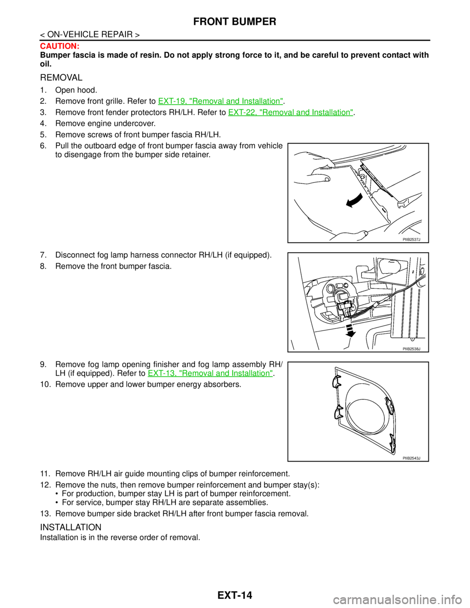
CAUTION:
Bumper fascia is made of resin. Do not apply strong force to it, and be careful to prevent contact with
oil.
REMOVAL
1. Open hood.
2. Remove front grille. Refer to EXT-19, "
Removal and Installation".
3. Remove front fender protectors RH/LH. Refer to EXT-22, "
Removal and Installation".
4. Remove engine undercover.
5. Remove screws of front bumper fascia RH/LH.
6. Pull the outboard edge of front bumper fascia away from vehicle
to disengage from the bumper side retainer.
7. Disconnect fog lamp harness connector RH/LH (if equipped).
8. Remove the front bumper fascia.
9. Remove fog lamp opening finisher and fog lamp assembly RH/
LH (if equipped). Refer to EXT-13, "
Removal and Installation".
10. Remove upper and lower bumper energy absorbers.
11. Remove RH/LH air guide mounting clips of bumper reinforcement.
12. Remove the nuts, then remove bumper reinforcement and bumper stay(s):
For production, bumper stay LH is part of bumper reinforcement.
For service, bumper stay RH/LH are separate assemblies.
13. Remove bumper side bracket RH/LH after front bumper fascia removal.
INSTALLATION
Installation is in the reverse order of removal.
PIIB2537J
PIIB2538J
PIIB2543J
Page 3123 of 5883

FRONT GRILLE
EXT-19
< ON-VEHICLE REPAIR >
C
D
E
F
G
H
I
J
L
MA
B
EXT
N
O
P
FRONT GRILLE
Removal and InstallationINFOID:0000000001568929
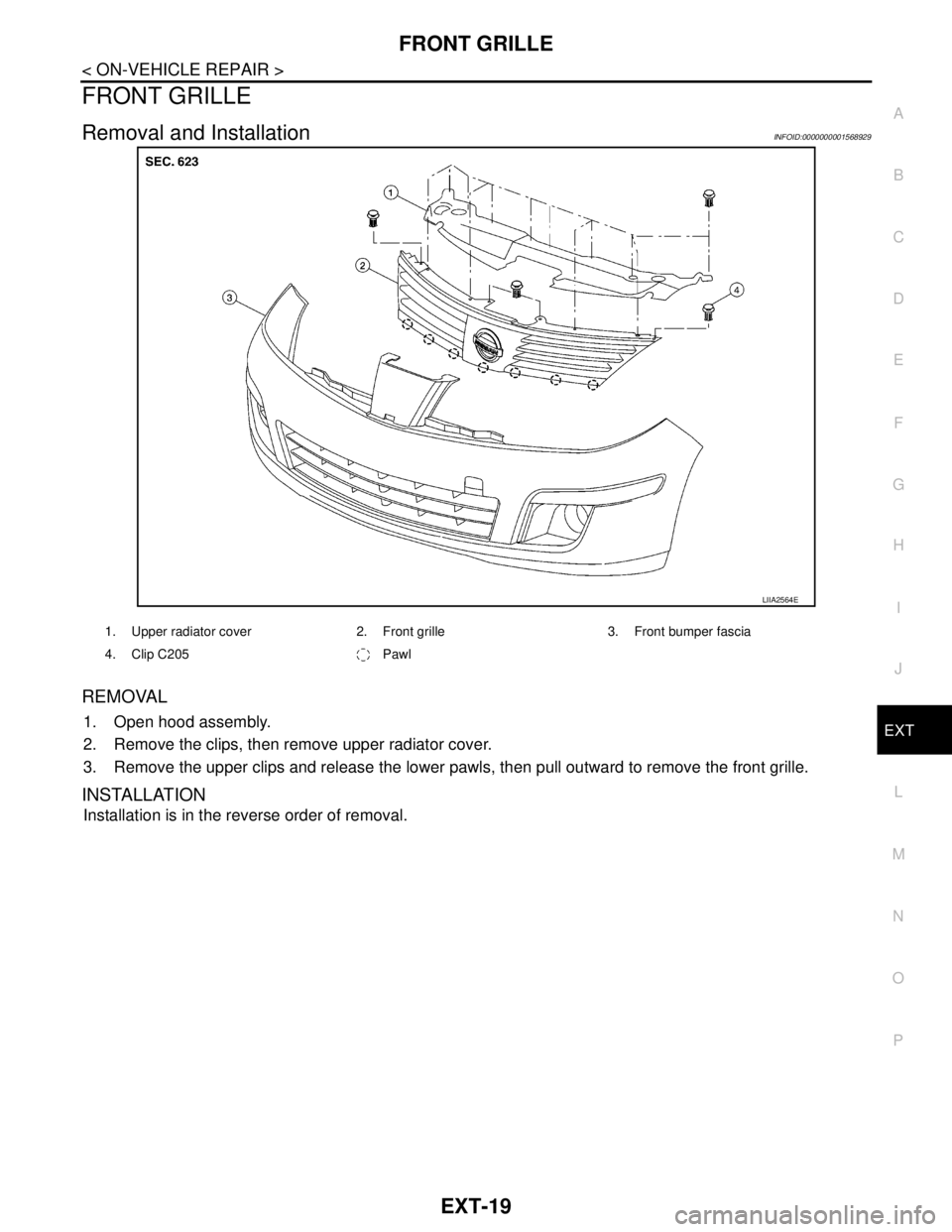
REMOVAL
1. Open hood assembly.
2. Remove the clips, then remove upper radiator cover.
3. Remove the upper clips and release the lower pawls, then pull outward to remove the front grille.
INSTALLATION
Installation is in the reverse order of removal.
LIIA2564E
1. Upper radiator cover 2. Front grille 3. Front bumper fascia
4. Clip C205 Pawl
Page 3409 of 5883
![NISSAN TIIDA 2007 Service Repair Manual HAC-76
< SYMPTOM DIAGNOSIS >[MANUAL AIR CONDITIONER]
INSUFFICIENT COOLING
Testing must be performed as follows:
Test Reading
Recirculating-to-discharge Air Temperature Table
Ambient Air Temperature-to NISSAN TIIDA 2007 Service Repair Manual HAC-76
< SYMPTOM DIAGNOSIS >[MANUAL AIR CONDITIONER]
INSUFFICIENT COOLING
Testing must be performed as follows:
Test Reading
Recirculating-to-discharge Air Temperature Table
Ambient Air Temperature-to](/manual-img/5/57395/w960_57395-3408.png)
HAC-76
< SYMPTOM DIAGNOSIS >[MANUAL AIR CONDITIONER]
INSUFFICIENT COOLING
Testing must be performed as follows:
Test Reading
Recirculating-to-discharge Air Temperature Table
Ambient Air Temperature-to-operating Pressure Table
*1: With blower control dial in the "1" position
*2: With blower control dial in the "4" position.
Test ReadingINFOID:0000000001547076
Recirculating-to-discharge Air Temperature Table
Vehicle condition Indoors or in the shade (in a well-ventilated place)
Doors Closed
Door window Open
Hood Open
TEMP. Max. COLD
Mode control dial
(Ventilation) set
Intake door lever
(Recirculation) set
Blower speedMax. speed set
Engine speed Idle speed
Operate the air conditioning system for 10 minutes before taking measurements.
Inside air (Recirculating air) at blower assembly inlet
Discharge air temperature at center ventilator
°C (°F) Relative humidity
%Air temperature
°C (°F)
50 - 6020 (68) 7.2 - 9.1 (45 - 48)
25 (77) 11.4 - 13.8 (53 - 57)
30 (86) 15.5 - 18.4 (60 - 65)
35 (95) 20.3 - 23.7 (69 - 75)
60 - 7020 (68) 9.1 - 10.9 (48 - 52)
25 (77) 13.8 - 16.2 (57 - 61)
30 (86) 18.4 - 21.3 (65 - 70)
35 (95) 23.7 - 27.1 (75 - 81)
Ambient air
High-pressure (Discharge side)
kPa (bar, kg/cm
2 , psi)Low-pressure (Suction side)
kPa (bar, kg/cm2 , psi) Relative humidity
%Air temperature
°C (°F)
50 - 7020 (68)843 - 1,036 *1
(11.08 - 13.63, 8.6 - 10.6, 122 - 150)159.0 - 194.0
(1.59 - 1.94, 1.62 - 1.98, 23.1 - 28.1)
25 (77)1,094 - 1,338 *1
(10.94 - 13.38, 11.2 - 13.6, 159 - 194)196.3 - 240.0
(1.96 - 2.40, 2.00 - 2.45, 28.5 - 34.8)
30 (86)1,298 - 1,590 *1
(12.98 - 15.90, 13.2 - 16.2, 188 - 231)248.0 - 302.7
(2.48 - 3.03, 2.53 - 3.09, 36.0 - 43.9)
35 (95)1,383 - 1,688 *2
(13.83 - 16.88, 14.1 - 17.2, 201 - 245)308.8 - 377.4
(3.09 - 3.77, 3.15 - 3.85, 44.8 - 54.7)
40 (104)1,628 - 1,988 *2
(16.28 - 19.88, 16.6 - 20.3, 236 - 288)377.4 - 461.2
(3.77 - 4.61, 3.85 - 4.70, 54.7 - 66.8)
Page 3522 of 5883
![NISSAN TIIDA 2007 Service Repair Manual INSUFFICIENT COOLING
HAC-189
< SYMPTOM DIAGNOSIS >[AUTO AIR CONDITIONER (W/O NAVI)]
C
D
E
F
G
H
J
K
L
MA
B
HAC
N
O
P
Testing must be performed as follows:
Test ReadingINFOID:0000000001547455
TEST READ NISSAN TIIDA 2007 Service Repair Manual INSUFFICIENT COOLING
HAC-189
< SYMPTOM DIAGNOSIS >[AUTO AIR CONDITIONER (W/O NAVI)]
C
D
E
F
G
H
J
K
L
MA
B
HAC
N
O
P
Testing must be performed as follows:
Test ReadingINFOID:0000000001547455
TEST READ](/manual-img/5/57395/w960_57395-3521.png)
INSUFFICIENT COOLING
HAC-189
< SYMPTOM DIAGNOSIS >[AUTO AIR CONDITIONER (W/O NAVI)]
C
D
E
F
G
H
J
K
L
MA
B
HAC
N
O
P
Testing must be performed as follows:
Test ReadingINFOID:0000000001547455
TEST READING
Recirculating-to-discharge Air Temperature Table
Ambient Air Temperature-to-operating Pressure Table
*1: In the motor fan low-speed control
*2: In the motor fan high-speed control
Trouble Diagnoses for Unusual PressureINFOID:0000000001547456
TROUBLE DIAGNOSIS FOR UNUSUAL PRESSURE
Vehicle condition Indoors or in the shade (in a well-ventilated place)
Doors Closed
Door window Open
Hood Open
TEMP. Max. COLD
Mode switch
(Ventilation) set
Recirculation (REC) switch
(Recirculation) set
Fan (blower) speedMax. speed set
Engine speed Idle speed
Operate the air conditioning system for 10 minutes before taking measurements.
Inside air (Recirculating air) at blower assembly inlet
Discharge air temperature at center ventilator
°C (°F) Relative humidity
%Air temperature
°C (°F)
50 - 6020 (68) 7.2 - 9.1 (45 - 48)
25 (77) 11.4 - 13.8 (53 - 57)
30 (86) 15.5 - 18.4 (60 - 65)
35 (95) 20.3 - 23.7 (69 - 75)
60 - 7020 (68) 9.1 - 10.9 (48 - 52)
25 (77) 13.8 - 16.2 (57 - 61)
30 (86) 18.4 - 21.3 (65 - 70)
35 (95) 23.7 - 27.1 (75 - 81)
Ambient air
High-pressure (Discharge side)
kPa (bar, kg/cm
2, psi)Low-pressure (Suction side)
kPa (bar, kg/cm2, psi) Relative humidity
%Air temperature
°C (°F)
50 - 7020 (68)843 - 1,036 *1
(11.08 - 13.63, 8.6 - 10.6, 122 - 150)159.0 - 194.0
(1.59 - 1.94, 1.62 - 1.98, 23.1 - 28.1)
25 (77)1,094 - 1,338 *1
(10.94 - 13.38, 11.2 - 13.6, 159 - 194)196.3 - 240.0
(1.96 - 2.40, 2.00 - 2.45, 28.5 - 34.8)
30 (86)1,298 - 1,590 *1
(12.98 - 15.90, 13.2 - 16.2, 188 - 231)248.0 - 302.7
(2.48 - 3.03, 2.53 - 3.09, 36.0 - 43.9)
35 (95)1,383 - 1,688 *2
(13.83 - 16.88, 14.1 - 17.2, 201 - 245)308.8 - 377.4
(3.09 - 3.77, 3.15 - 3.85, 44.8 - 54.7)
40 (104)1,628 - 1,988 *2
(16.28 - 19.88, 16.6 - 20.3, 236 - 288)377.4 - 461.2
(3.77 - 4.61, 3.85 - 4.70, 54.7 - 66.8)
Page 3636 of 5883
![NISSAN TIIDA 2007 Service Repair Manual INSUFFICIENT COOLING
HAC-303
< SYMPTOM DIAGNOSIS >[AUTO AIR CONDITIONER (W/NAVI)]
C
D
E
F
G
H
J
K
L
MA
B
HAC
N
O
P
Testing must be performed as follows:
Test ReadingINFOID:0000000001547377
TEST READIN NISSAN TIIDA 2007 Service Repair Manual INSUFFICIENT COOLING
HAC-303
< SYMPTOM DIAGNOSIS >[AUTO AIR CONDITIONER (W/NAVI)]
C
D
E
F
G
H
J
K
L
MA
B
HAC
N
O
P
Testing must be performed as follows:
Test ReadingINFOID:0000000001547377
TEST READIN](/manual-img/5/57395/w960_57395-3635.png)
INSUFFICIENT COOLING
HAC-303
< SYMPTOM DIAGNOSIS >[AUTO AIR CONDITIONER (W/NAVI)]
C
D
E
F
G
H
J
K
L
MA
B
HAC
N
O
P
Testing must be performed as follows:
Test ReadingINFOID:0000000001547377
TEST READING
Recirculating-to-discharge Air Temperature Table
Ambient Air Temperature-to-operating Pressure Table
*1: In the blower motor low-speed control
*2: In the blower motor high-speed control
Trouble Diagnoses for Unusual PressureINFOID:0000000001547378
TROUBLE DIAGNOSIS FOR UNUSUAL PRESSURE
Vehicle condition Indoors or in the shade (in a well-ventilated place)
Doors Closed
Door window Open
Hood Open
TEMP. Max. COLD
Mode control dial
(Ventilation) set
Intake switch
(Recirculation) set
Blower speedMax. speed set
Engine speed Idle speed
Operate the air conditioning system for 10 minutes before taking measurements.
Inside air (Recirculating air) at blower assembly inlet
Discharge air temperature at center ventilator
°C (°F) Relative humidity
%Air temperature
°C (°F)
50 - 6020 (68) 7.2 - 9.1 (45 - 48)
25 (77) 11.4 - 13.8 (53 - 57)
30 (86) 15.5 - 18.4 (60 - 65)
35 (95) 20.3 - 23.7 (69 - 75)
60 - 7020 (68) 9.1 - 10.9 (48 - 52)
25 (77) 13.8 - 16.2 (57 - 61)
30 (86) 18.4 - 21.3 (65 - 70)
35 (95) 23.7 - 27.1 (75 - 81)
Ambient air
High-pressure (Discharge side)
kPa (bar, kg/cm
2, psi)Low-pressure (Suction side)
kPa (bar, kg/cm2, psi) Relative humidity
%Air temperature
°C (°F)
50 - 7020 (68)843 - 1,036 *1
(11.08 - 13.63, 8.6 - 10.6, 122 - 150)159.0 - 194.0
(1.59 - 1.94, 1.62 - 1.98, 23.1 - 28.1)
25 (77)1,094 - 1,338 *1
(10.94 - 13.38, 11.2 - 13.6, 159 - 194)196.3 - 240.0
(1.96 - 2.40, 2.00 - 2.45, 28.5 - 34.8)
30 (86)1,298 - 1,590 *1
(12.98 - 15.90, 13.2 - 16.2, 188 - 231)248.0 - 302.7
(2.48 - 3.03, 2.53 - 3.09, 36.0 - 43.9)
35 (95)1,383 - 1,688 *2
(13.83 - 16.88, 14.1 - 17.2, 201 - 245)308.8 - 377.4
(3.09 - 3.77, 3.15 - 3.85, 44.8 - 54.7)
40 (104)1,628 - 1,988 *2
(16.28 - 19.88, 16.6 - 20.3, 236 - 288)377.4 - 461.2
(3.77 - 4.61, 3.85 - 4.70, 54.7 - 66.8)
Page 3731 of 5883

IP-16
< SERVICE INFORMATION >
INSTRUMENT PANEL ASSEMBLY
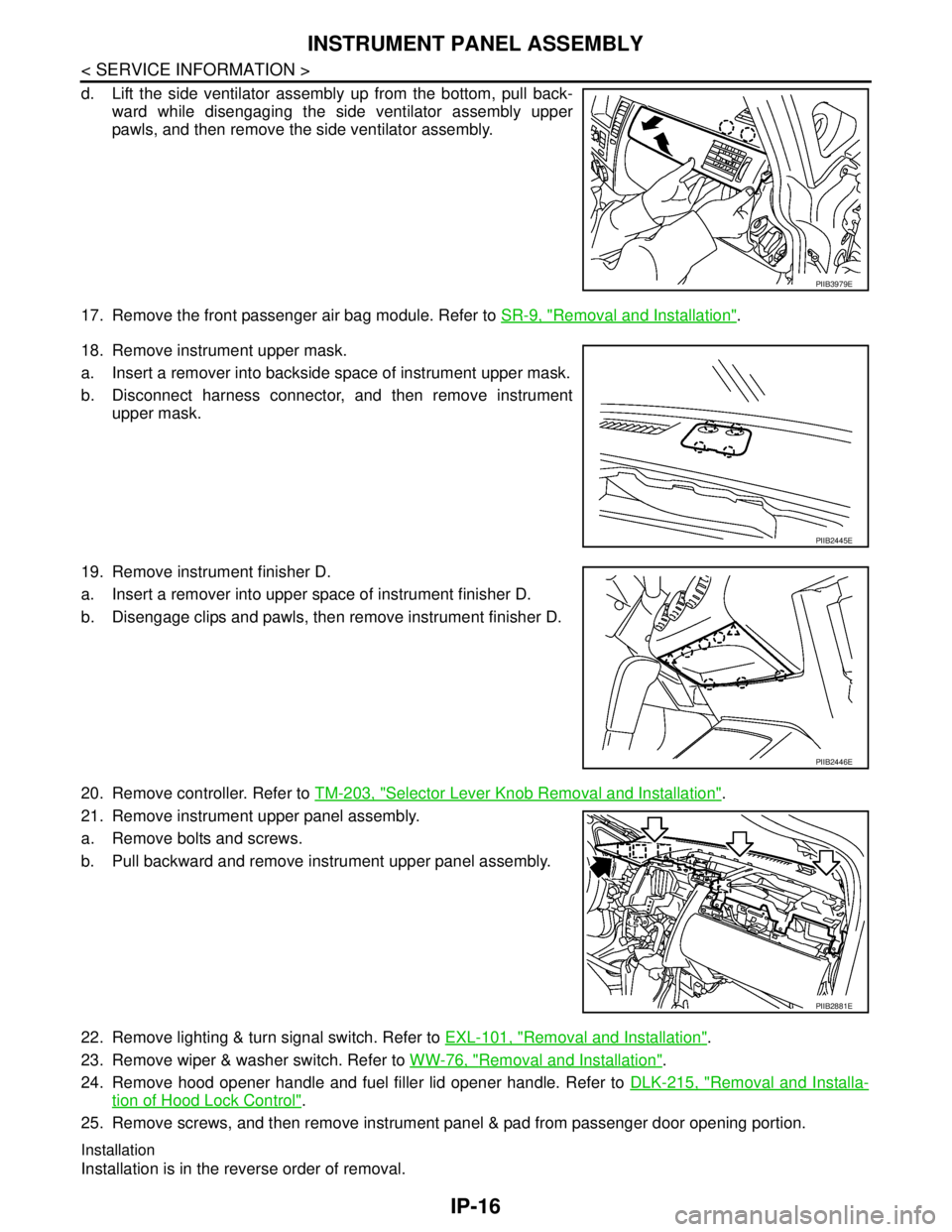
d. Lift the side ventilator assembly up from the bottom, pull back-
ward while disengaging the side ventilator assembly upper
pawls, and then remove the side ventilator assembly.
17. Remove the front passenger air bag module. Refer to SR-9, "
Removal and Installation".
18. Remove instrument upper mask.
a. Insert a remover into backside space of instrument upper mask.
b. Disconnect harness connector, and then remove instrument
upper mask.
19. Remove instrument finisher D.
a. Insert a remover into upper space of instrument finisher D.
b. Disengage clips and pawls, then remove instrument finisher D.
20. Remove controller. Refer to TM-203, "
Selector Lever Knob Removal and Installation".
21. Remove instrument upper panel assembly.
a. Remove bolts and screws.
b. Pull backward and remove instrument upper panel assembly.
22. Remove lighting & turn signal switch. Refer to EXL-101, "
Removal and Installation".
23. Remove wiper & washer switch. Refer to WW-76, "
Removal and Installation".
24. Remove hood opener handle and fuel filler lid opener handle. Refer to DLK-215, "
Removal and Installa-
tion of Hood Lock Control".
25. Remove screws, and then remove instrument panel & pad from passenger door opening portion.
Installation
Installation is in the reverse order of removal.
PIIB3979E
PIIB2445E
PIIB2446E
PIIB2881E
Page 4246 of 5883

MA-6
< ON-VEHICLE MAINTENANCE >
GENERAL MAINTENANCE
ON-VEHICLE MAINTENANCE
GENERAL MAINTENANCE
General MaintenanceINFOID:0000000001277597
General maintenance includes those items which should be checked during the normal day-to-day operation
of the vehicle. They are essential if the vehicle is to continue operating properly. The owners can perform the
checks and inspections themselves or they can have their NISSAN dealers do them for a nominal charge.
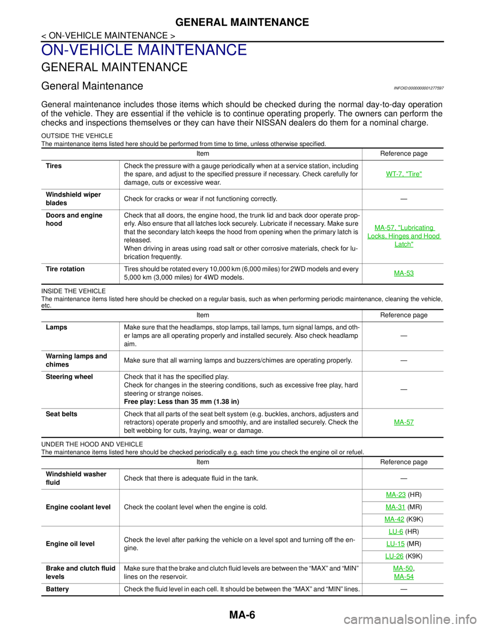
OUTSIDE THE VEHICLE
The maintenance items listed here should be performed from time to time, unless otherwise specified.
INSIDE THE VEHICLE
The maintenance items listed here should be checked on a regular basis, such as when performing periodic maintenance, cleaning the vehicle,
etc.
UNDER THE HOOD AND VEHICLE
The maintenance items listed here should be checked periodically e.g. each time you check the engine oil or refuel.
Item Reference page
TiresCheck the pressure with a gauge periodically when at a service station, including
the spare, and adjust to the specified pressure if necessary. Check carefully for
damage, cuts or excessive wear.WT-7, "
Tire"
Windshield wiper
bladesCheck for cracks or wear if not functioning correctly. —
Doors and engine
hoodCheck that all doors, the engine hood, the trunk lid and back door operate prop-
erly. Also ensure that all latches lock securely. Lubricate if necessary. Make sure
that the secondary latch keeps the hood from opening when the primary latch is
released.
When driving in areas using road salt or other corrosive materials, check for lu-
brication frequently.MA-57, "
Lubricating
Locks, Hinges and Hood
Latch"
Tire rotationTires should be rotated every 10,000 km (6,000 miles) for 2WD models and every
5,000 km (3,000 miles) for 4WD models.MA-53
Item Reference page
LampsMake sure that the headlamps, stop lamps, tail lamps, turn signal lamps, and oth-
er lamps are all operating properly and installed securely. Also check headlamp
aim.—
Warning lamps and
chimesMake sure that all warning lamps and buzzers/chimes are operating properly. —
Steering wheelCheck that it has the specified play.
Check for changes in the steering conditions, such as excessive free play, hard
steering or strange noises.
Free play: Less than 35 mm (1.38 in)—
Seat beltsCheck that all parts of the seat belt system (e.g. buckles, anchors, adjusters and
retractors) operate properly and smoothly, and are installed securely. Check the
belt webbing for cuts, fraying, wear or damage.MA-57
Item Reference page
Windshield washer
fluidCheck that there is adequate fluid in the tank. —
Engine coolant levelCheck the coolant level when the engine is cold.MA-23
(HR)
MA-31
(MR)
MA-42
(K9K)
Engine oil levelCheck the level after parking the vehicle on a level spot and turning off the en-
gine.LU-6
(HR)
LU-15
(MR)
LU-26
(K9K)
Brake and clutch fluid
levelsMake sure that the brake and clutch fluid levels are between the “MAX” and “MIN”
lines on the reservoir.MA-50
,
MA-54
BatteryCheck the fluid level in each cell. It should be between the “MAX” and “MIN” lines. —
Page 4363 of 5883

MWI-56
< ECU DIAGNOSIS >
BCM (BODY CONTROL MODULE)
ENGINE RUNEngine stopped OFF
Engine running ON
ENGINE STATUS
NOTE:
Diesel engine models
onlyEngine stopped STOP
While the engine stalls STALL
Engine running RUN
At engine cranking CRA
FA N O N S I GFan switch OFF OFF
Fan switch ON ON
FR FOG SWFront fog lamp switch OFF OFF
Front fog lamp switch ON ON
FR WASHER SWFront washer switch OFF OFF
Front washer switch ON ON
FR WIPER LOWFront wiper switch OFF OFF
Front wiper switch LO ON
FR WIPER HIFront wiper switch OFF OFF
Front wiper switch HI ON
FR WIPER INTFront wiper switch OFF OFF
Front wiper switch INT ON
FR WIPER STOPAny position other than front wiper stop position OFF
Front wiper stop position ON
HAZARD SWWhen hazard switch is not pressed OFF
When hazard switch is pressed ON
LIGHT SW 1STLighting switch OFF OFF
Lighting switch 1st ON
H/L SW POSHeadlamp switch OFF OFF
Headlamp switch 1st ON
HI BEAM SWHigh beam switch OFF OFF
High beam switch HI ON
HOOD SWClose the hood
NOTE:
Vehicles without theft warning system are OFF-fixedOFF
Open the hood ON
H/L WASH SWNOTE:
The item is indicated, but not monitoredOFF
IGN ON SWIgnition switch OFF or ACC OFF
Ignition switch ON ON
IGN SW CANIgnition switch OFF or ACC OFF
Ignition switch ON ON
INT VOLUME Wiper intermittent dial is in a dial position 1 - 7 1 - 7
I-KEY LOCK
1LOCK button of Intelligent Key is not pressed OFF
LOCK button of Intelligent Key is pressed ON
I-KEY UNLOCK
1UNLOCK button of Intelligent Key is not pressed OFF
UNLOCK button of Intelligent Key is pressed ON
KEY SW
2Mechanical key is removed from key cylinder OFF
Mechanical key is inserted to key cylinder ON Monitor Item Condition Value/Status