Page 5690 of 5883
PTC HEATER
VTL-29
< ON-VEHICLE REPAIR >[AUTOMATIC AIR CONDITIONER]
C
D
E
F
G
H
J
K
L
MA
B
VTL
N
O
P
3. Remove the water temperature sensor screw (A), and then
remove the water temperature sensor (1).
INSTALLATION
Installation is in the reverse order of removal.
SJIA0934E
Page 5697 of 5883
VTL-36
< ON-VEHICLE REPAIR >[MANUAL AIR CONDITIONER]
INTAKE SENSOR
INTAKE SENSOR
Removal and InstallationINFOID:0000000001700349
REMOVAL
1. Remove the evaporator. Refer to VTL-41, "Removal and Installation of Evaporator".
CAUTION:
Cap or wrap the joint of the pipe with suitable material such as vinyl tape to avoid the entry of air.
2. Remove the intake sensor (1) from the evaporator (2).
CAUTION:
Mark the position of intake sensor on the evaporator for
installation.
INSTALLATION
Installation is in the reverse order of removal.
CAUTION:
Replace O-rings for A/C piping with new ones, and then apply compressor oil to it when installing it.
Install the intake sensor in the same position as the original intake sensor.
When recharging refrigerant, check for leaks.
ZJIA0798J
Page 5701 of 5883
VTL-40
< ON-VEHICLE REPAIR >[MANUAL AIR CONDITIONER]
A/C UNIT ASSEMBLY
43. Cooler pipe assembly 44. Water temperature sensor 45. Full hot switch
46. PTC heater 47. PTC control unit
Page 5714 of 5883
![NISSAN TIIDA 2007 Service Repair Manual PTC HEATER
VTL-53
< ON-VEHICLE REPAIR >[MANUAL AIR CONDITIONER]
C
D
E
F
G
H
J
K
L
MA
B
VTL
N
O
P
PTC HEATER
Removal and Installation of PTC Control UnitINFOID:0000000001696541
REMOVAL
1. Remove the in NISSAN TIIDA 2007 Service Repair Manual PTC HEATER
VTL-53
< ON-VEHICLE REPAIR >[MANUAL AIR CONDITIONER]
C
D
E
F
G
H
J
K
L
MA
B
VTL
N
O
P
PTC HEATER
Removal and Installation of PTC Control UnitINFOID:0000000001696541
REMOVAL
1. Remove the in](/manual-img/5/57395/w960_57395-5713.png)
PTC HEATER
VTL-53
< ON-VEHICLE REPAIR >[MANUAL AIR CONDITIONER]
C
D
E
F
G
H
J
K
L
MA
B
VTL
N
O
P
PTC HEATER
Removal and Installation of PTC Control UnitINFOID:0000000001696541
REMOVAL
1. Remove the instrument lower finisher and instrument lower cover (LH) for LHD only. Refer to IP-11,
"Removal and Installation".
2. Remove the glove box assembly and instrument lower cover (RH) for RHD only. Refer to IP-11, "
Removal
and Installation".
3. Disconnect connector (A).
4. Remove mounting screws (B), and then remove PTC control
unit (1).
INSTALLATION
Installation is basically the reverse order of removal.
Removal and Installation of PTC HeaterINFOID:0000000001696542
REMOVAL
1. Remove instrument panel and pad. Refer to IP-11, "Removal and Installation".
2. Disconnect PTC heater connector and full hot switch connector.
3. Remove mounting screws (A), and then remove PTC heater (1)
and full hot switch (2).
INSTALLATION
Installation is basically the reverse order of removal.
Removal and Installation of Water Temperature SensorINFOID:0000000001696543
REMOVAL
1. Remove A/C unit assembly. Refer to VTL-37, "Removal and Installation".
2. Remove heater pipe cover. Refer to VTL-39, "
Disassembly and Assembly".
SJIA0776E
SJIA0774E
Page 5715 of 5883
VTL-54
< ON-VEHICLE REPAIR >[MANUAL AIR CONDITIONER]
PTC HEATER
3. Remove mounting screw (A), and then remove water tempera-
ture sensor (1).
INSTALLATION
Installation is basically the reverse order of removal.
SJIA0934E
Page 5752 of 5883

WCS
COMBINATION METER
WCS-37
< ECU DIAGNOSIS >
C
D
E
F
G
H
I
J
K
L
MB A
O
P
ECU DIAGNOSIS
COMBINATION METER
Reference ValueINFOID:0000000001728308
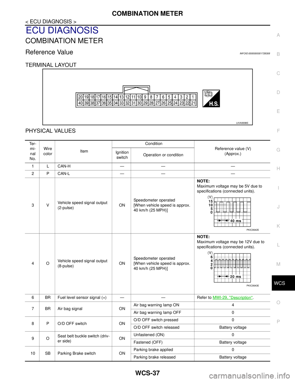
TERMINAL LAYOUT
PHYSICAL VALUES
LKIA0698E
Te r -
mi-
nal
No.Wire
colorItemCondition
Reference value (V)
(Approx.) Ignition
switchOperation or condition
1 L CAN-H — — —
2 P CAN-L — — —
3VVehicle speed signal output
(2-pulse)ONSpeedometer operated
[When vehicle speed is approx.
40 km/h (25 MPH)] NOTE:
Maximum voltage may be 5V due to
specifications (connected units).
4OVehicle speed signal output
(8-pulse)ONSpeedometer operated
[When vehicle speed is approx.
40 km/h (25 MPH)]NOTE:
Maximum voltage may be 12V due to
specifications (connected units).
6 BR Fuel level sensor signal (+) — — Refer to MWI-29, "
Description".
7 BR Air bag signal ONAir bag warning lamp ON 4
Air bag warning lamp OFF 0
8 P O/D OFF switch ONO/D OFF switch pressed 0
O/D OFF switch released Battery voltage
9OSeat belt buckle switch (driv-
er side)ONUnfastened (ON) 0
Fastened (OFF) Battery voltage
10 SB Parking Brake switch ONParking brake applied 0
Parking brake released Battery voltage
PKIC0642E
PKIC0643E
Page 5753 of 5883

WCS-38
< ECU DIAGNOSIS >
COMBINATION METER
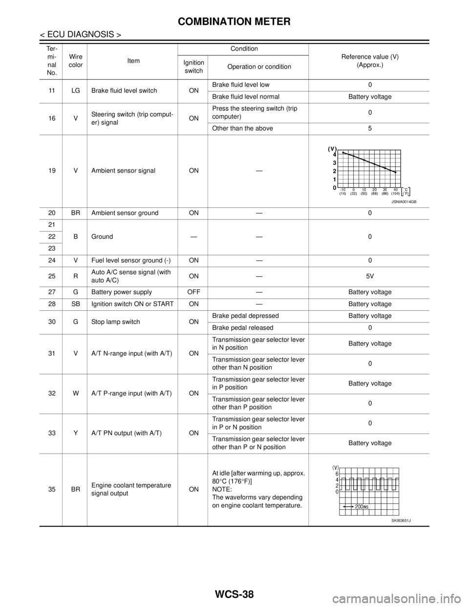
11 LG Brake fluid level switch ONBrake fluid level low 0
Brake fluid level normal Battery voltage
16 VSteering switch (trip comput-
er) signalONPress the steering switch (trip
computer)0
Other than the above 5
19 V Ambient sensor signal ON —
20 BR Ambient sensor ground ON — 0
21
BGround — — 0 22
23
24 V Fuel level sensor ground (-) ON — 0
25 RAuto A/C sense signal (with
auto A/C)ON — 5V
27 G Battery power supply OFF — Battery voltage
28 SB Ignition switch ON or START ON — Battery voltage
30 G Stop lamp switch ONBrake pedal depressed Battery voltage
Brake pedal released 0
31 V A/T N-range input (with A/T) ONTransmission gear selector lever
in N positionBattery voltage
Transmission gear selector lever
other than N position0
32 W A/T P-range input (with A/T) ONTransmission gear selector lever
in P positionBattery voltage
Transmission gear selector lever
other than P position0
33 Y A/T PN output (with A/T) ONTransmission gear selector lever
in P or N position0
Transmission gear selector lever
other than P or N positionBattery voltage
35 BREngine coolant temperature
signal outputONAt idle [after warming up, approx.
80°C (176°F)]
NOTE:
The waveforms vary depending
on engine coolant temperature. Te r -
mi-
nal
No.Wire
colorItemCondition
Reference value (V)
(Approx.) Ignition
switchOperation or condition
JSNIA0014GB
SKIB3651J
Page 5754 of 5883
WCS
COMBINATION METER
WCS-39
< ECU DIAGNOSIS >
C
D
E
F
G
H
I
J
K
L
MB A
O
P36 L Oil level sensor signal ON —Refer to MWI-32, "
Component Inspec-
tion (With Diesel)" or MWI-33, "Compo-
nent Inspection (Without Diesel)".
NOTE:
The measurement cannot be performed
because the signal is only input for a
moment when the ignition switch is
turned ON.
37 O Oil level sensor signal ground ON — 0
38 L Generator ONGenerator voltage low 0
Generator voltage normal Battery voltage Te r -
mi-
nal
No.Wire
colorItemCondition
Reference value (V)
(Approx.) Ignition
switchOperation or condition