2007 NISSAN TIIDA sensor
[x] Cancel search: sensorPage 5773 of 5883

WCS-58
< ECU DIAGNOSIS >
BCM (BODY CONTROL MODULE)
1: With Intelligent Key
2: With remote keyless entry system
3: HatchbackKEYLESS LOCK
2LOCK button of key fob is not pressed OFF
LOCK button of key fob is pressed ON
KEYLESS UNLOCK
2UNLOCK button of key fob is not pressed OFF
UNLOCK button of key fob is pressed ON
LIT-SEN FAILLight & rain sensor is in normal condition OK
Light & rain sensor is with internal error NOTOK
OIL PRESS SW Ignition switch OFF or ACC
Engine runningOFF
Ignition switch ON ON
OUT SIDE TEMP
NOTE:
Diesel engine modelsIgnition switch ONApproximately the same as outside
air temperature
PASSING SWOther than lighting switch PASS OFF
Lighting switch PASS ON
PUSH SW
1Return to ignition switch to LOCK position OFF
Press ignition switch ON
REAR DEF SWRear window defogger switch OFF OFF
Rear window defogger switch ON ON
RKE LOCK AND
UNLOCK
2NOTE:
The item is indicated, but not monitoredOFF
ON
RR FOG SWRear fog lamp switch OFF OFF
Rear fog lamp switch ON ON
RR WASHER SW
3Rear washer switch OFF OFF
Rear washer switch ON ON
RR WIPER INT
3Rear wiper switch OFF OFF
Rear wiper switch INT ON
RR WIPER ON
3 Rear wiper switch OFF OFF
Rear wiper switch ON ON
RR WIPER STOP
3Rear wiper stop position OFF
Other than rear wiper stop position ON
TAIL LAMP SWLighting switch OFF OFF
Lighting switch 1ST ON
TRNK OPNR SWWhen back door opener switch is not pressed OFF
When back door opener switch is pressed ON
TURN SIGNAL LTurn signal switch OFF OFF
Turn signal switch LH ON
TURN SIGNAL RTurn signal switch OFF OFF
Turn signal switch RH ON
UNLOCK WITH DRNOTE:
The item is indicated, but not monitoredOFF
ON
VEHICLE SPEED While driving Equivalent to speedometer reading Monitor Item Condition Value/Status
Page 5783 of 5883
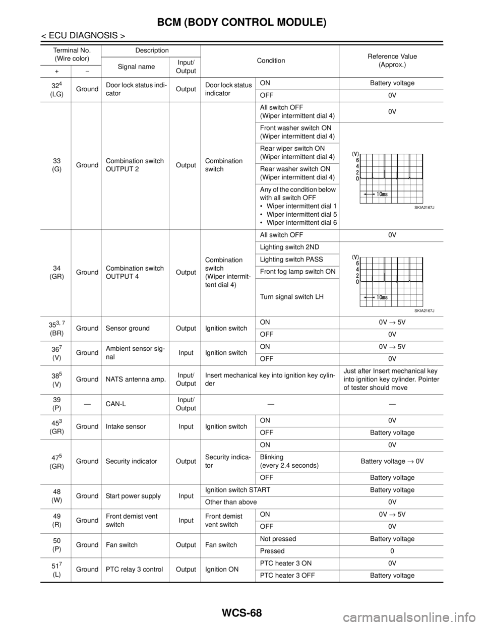
WCS-68
< ECU DIAGNOSIS >
BCM (BODY CONTROL MODULE)
324
(LG)GroundDoor lock status indi-
catorOutputDoor lock status
indicatorON Battery voltage
OFF 0V
33
(G)GroundCombination switch
OUTPUT 2OutputCombination
switchAll switch OFF
(Wiper intermittent dial 4)0V
Front washer switch ON
(Wiper intermittent dial 4)
Rear wiper switch ON
(Wiper intermittent dial 4)
Rear washer switch ON
(Wiper intermittent dial 4)
Any of the condition below
with all switch OFF
Wiper intermittent dial 1
Wiper intermittent dial 5
Wiper intermittent dial 6
34
(GR)GroundCombination switch
OUTPUT 4OutputCombination
switch
(Wiper intermit-
tent dial 4)All switch OFF 0V
Lighting switch 2ND
Lighting switch PASS
Front fog lamp switch ON
Turn signal switch LH
35
3, 7
(BR)Ground Sensor ground Output Ignition switchON 0V → 5V
OFF 0V
36
7
(V)GroundAmbient sensor sig-
nalInput Ignition switchON 0V → 5V
OFF 0V
38
5
(V)Ground NATS antenna amp.Input/
OutputInsert mechanical key into ignition key cylin-
derJust after Insert mechanical key
into ignition key cylinder. Pointer
of tester should move
39
(P)—CAN-LInput/
Output——
45
3
(GR)Ground Intake sensor Input Ignition switchON 0V
OFF Battery voltage
47
5
(GR)Ground Security indicator OutputSecurity indica-
torON 0V
Blinking
(every 2.4 seconds)Battery voltage → 0V
OFF Battery voltage
48
(W)Ground Start power supply InputIgnition switch START Battery voltage
Other than above 0V
49
(R)GroundFront demist vent
switchInputFront demist
vent switchON 0V → 5V
OFF 0V
50
(P)Ground Fan switch Output Fan switchNot pressed Battery voltage
Pressed 0
51
7
(L)Ground PTC relay 3 control Output Ignition ONPTC heater 3 ON 0V
PTC heater 3 OFF Battery voltage Te r m i n a l N o .
(Wire color)Description
ConditionReference Value
(Approx.)
Signal nameInput/
Output +−
SKIA2167J
SKIA2167J
Page 5784 of 5883
WCS
BCM (BODY CONTROL MODULE)
WCS-69
< ECU DIAGNOSIS >
C
D
E
F
G
H
I
J
K
L
MB A
O
P
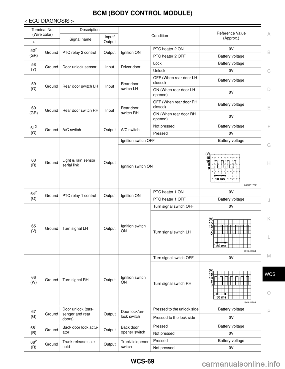
527
(GR)Ground PTC relay 2 control Output Ignition ONPTC heater 2 ON 0V
PTC heater 2 OFF Battery voltage
58
(Y)Ground Door unlock sensor Input Driver doorLock Battery voltage
Unlock 0V
59
(O)Ground Rear door switch LH InputRear door
switch LHOFF (When rear door LH
closed) Battery voltage
ON (When rear door LH
opened)0V
60
(GR)Ground Rear door switch RH InputRear door
switch RHOFF (When rear door RH
closed) Battery voltage
ON (When rear door RH
opened)0V
61
3
(O)Ground A/C switch Output A/C switchNot pressed Battery voltage
Pressed 0V
63
(R)GroundLight & rain sensor
serial linkOutputIgnition switch OFF Battery voltage
Ignition switch ON
64
7
(O)Ground PTC relay 1 control Output Ignition ONPTC heater 1 ON 0V
PTC heater 1 OFF Battery voltage
65
(V)Ground Turn signal LH OutputIgnition switch
ONTurn signal switch OFF 0V
Turn signal switch LH
66
(W)Ground Turn signal RH OutputIgnition switch
ONTurn signal switch OFF 0V
Turn signal switch RH
67
(G)GroundDoor unlock (pas-
senger and rear
doors)OutputDoor lock/un-
lock switchPressed to the unlock side Battery voltage
Pressed to the lock side 0V
68
1
(R)GroundBack door lock actu-
atorOutputBack door
opener switchPressed Battery voltage
Not pressed 0V
68
2
(R)GroundTrunk release sole-
noidOutputTrunk lid opener
switchPressed Battery voltage
Not pressed 0V Terminal No.
(Wire color)Description
ConditionReference Value
(Approx.)
Signal nameInput/
Output +−
MKIB0173E
SKIA1120J
SKIA1120J
Page 5803 of 5883

WW-1
DRIVER CONTROLS
C
D
E
F
G
H
I
J
K
M
SECTION WW
A
B
WW
N
O
P
CONTENTS
WIPER & WASHER
BASIC INSPECTION ....................................3
DIAGNOSIS AND REPAIR WORKFLOW ..........3
Work Flow .................................................................3
FUNCTION DIAGNOSIS ...............................4
FRONT WIPER AND WASHER SYSTEM ..........4
System Diagram ........................................................4
System Description ...................................................4
Component Parts Location ........................................7
Component Description ............................................8
REAR WIPER AND WASHER SYSTEM ............9
System Diagram ........................................................9
System Description ...................................................9
Component Parts Location ......................................11
Component Description ..........................................11
HEADLAMP WASHER SYSTEM .......................12
System Diagram ......................................................12
System Description .................................................12
Component Parts Location ......................................13
Component Description ..........................................13
DIAGNOSIS SYSTEM (BCM) ............................14
COMMON ITEM .........................................................14
COMMON ITEM : CONSULT-III Function (BCM -
COMMON ITEM) .....................................................
14
WIPER .......................................................................14
WIPER : CONSULT-III Function (BCM - WIPER) ....14
DIAGNOSIS SYSTEM (IPDM E/R) .....................16
Diagnosis Description .............................................16
CONSULT - III Function (IPDM E/R) .......................16
COMPONENT DIAGNOSIS .........................17
WIPER AND WASHER FUSE, FUSIBLE LINK
....
17
Description ..............................................................17
Diagnosis Procedure ...............................................17
FRONT WIPER MOTOR LO CIRCUIT ..............18
Component Function Check ....................................18
Diagnosis Procedure ...............................................18
FRONT WIPER MOTOR HI CIRCUIT ...............20
Component Function Check ....................................20
Diagnosis Procedure ...............................................20
FRONT WIPER AUTO STOP SIGNAL CIR-
CUIT ..................................................................
22
Component Function Check ....................................22
Diagnosis Procedure ...............................................22
FRONT WIPER MOTOR GROUND CIRCUIT ...24
Diagnosis Procedure ...............................................24
WASHER SWITCH ............................................25
Description ...............................................................25
Component Inspection .............................................25
LIGHT & RAIN SENSOR ..................................27
Description ...............................................................27
Diagnosis Procedure ...............................................27
REAR WIPER MOTOR CIRCUIT ......................28
Component Function Check ....................................28
Diagnosis Procedure ...............................................28
REAR WIPER AUTO STOP SIGNAL CIRCUIT
...
30
Component Function Check ....................................30
Diagnosis Procedure ...............................................30
HEADLAMP WASHER RELAY ........................32
Component Inspection .............................................32
HEADLAMP WASHER CIRCUIT ......................33
Component Function Check ....................................33
Diagnosis Procedure ...............................................33
FRONT WIPER AND WASHER SYSTEM ........36
Page 5804 of 5883

WW-2
Wiring Diagram .......................................................36
REAR WIPER AND WASHER SYSTEM ...........41
Wiring Diagram .......................................................41
HEADLAMP WASHER SYSTEM ......................47
Wiring Diagram .......................................................47
ECU DIAGNOSIS ........................................51
BCM (BODY CONTROL MODULE) ..................51
Reference Value .....................................................51
IPDM E/R (INTELLIGENT POWER DISTRI-
BUTION MODULE ENGINE ROOM) .................
52
Reference Value .....................................................52
Fail Safe .................................................................52
SYMPTOM DIAGNOSIS .............................54
WIPER AND WASHER SYSTEM SYMPTOMS
...
54
Symptom Table ......................................................54
NORMAL OPERATING CONDITION ................57
Description ..............................................................57
FRONT WIPER DOES NOT OPERATE ............58
Description ..............................................................58
Diagnosis Procedure ..............................................58
HEADLAMP WASHER DOES NOT OPER-
ATE ....................................................................
60
Description ..............................................................60
Diagnosis Procedure ..............................................60
PRECAUTION .............................................61
PRECAUTIONS .................................................61
Precaution for Supplemental Restraint System
(SRS) "AIR BAG" and "SEAT BELT PRE-TEN-
SIONER" .................................................................
61
Precaution for Procedure without Cowl Top Cover ...61
ON-VEHICLE REPAIR ................................62
HEADLAMP WASHER NOZZLE AND TUBE ...62
Exploded View ........................................................62
Removal and Installation .........................................62
Inspection ................................................................63
WASHER TANK ................................................64
Removal and Installation .........................................64
WASHER PUMP ................................................65
Removal and Installation .........................................65
HEADLAMP WASHER PUMP ..........................66
Removal and Installation .........................................66
FRONT WASHER NOZZLE AND TUBE ...........67
Washer Tube Layout ...............................................67
Removal and Installation .........................................67
Inspection ................................................................67
Adjustment ..............................................................68
FRONT WIPER ARM .........................................69
Exploded View ........................................................69
Removal and Installation .........................................70
Adjustment ..............................................................71
FRONT WIPER DRIVE ASSEMBLY .................72
Exploded View ........................................................72
Removal and Installation .........................................73
Adjustment ..............................................................73
RAIN SENSOR ..................................................75
Exploded View ........................................................75
Removal and Installation .........................................75
WIPER AND WASHER SWITCH ......................76
Exploded View ........................................................76
Removal and Installation .........................................76
REAR WIPER MOTOR ......................................77
Exploded View ........................................................77
Removal and Installation .........................................77
Adjustment ..............................................................78
REAR WASHER NOZZLE AND TUBE .............80
Washer Tube Layout ...............................................80
Removal and Installation .........................................80
Adjustment ..............................................................81
Page 5807 of 5883
FRONT WIPER AND WASHER SYSTEM
WW-5
< FUNCTION DIAGNOSIS >
C
D
E
F
G
H
I
J
K
MA
B
WW
N
O
P
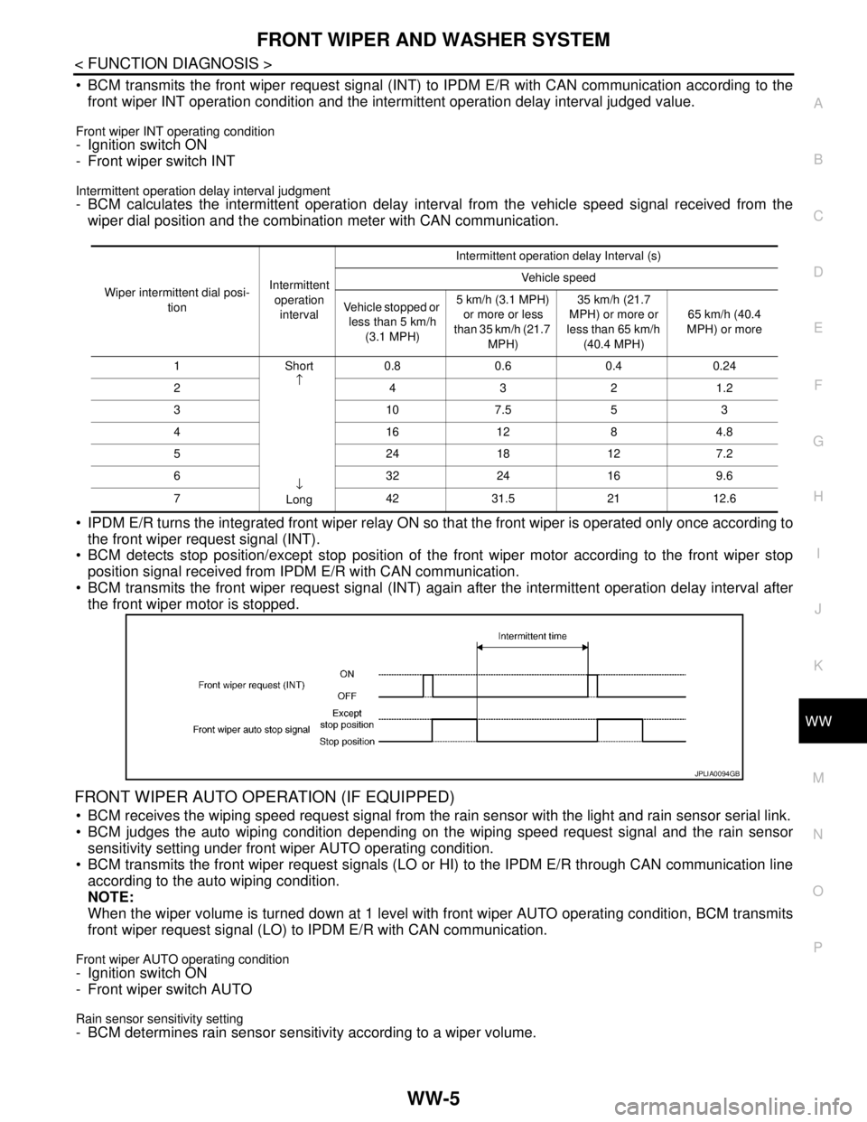
BCM transmits the front wiper request signal (INT) to IPDM E/R with CAN communication according to the
front wiper INT operation condition and the intermittent operation delay interval judged value.
Front wiper INT operating condition- Ignition switch ON
- Front wiper switch INT
Intermittent operation delay interval judgment- BCM calculates the intermittent operation delay interval from the vehicle speed signal received from the
wiper dial position and the combination meter with CAN communication.
IPDM E/R turns the integrated front wiper relay ON so that the front wiper is operated only once according to
the front wiper request signal (INT).
BCM detects stop position/except stop position of the front wiper motor according to the front wiper stop
position signal received from IPDM E/R with CAN communication.
BCM transmits the front wiper request signal (INT) again after the intermittent operation delay interval after
the front wiper motor is stopped.
FRONT WIPER AUTO OPERATION (IF EQUIPPED)
BCM receives the wiping speed request signal from the rain sensor with the light and rain sensor serial link.
BCM judges the auto wiping condition depending on the wiping speed request signal and the rain sensor
sensitivity setting under front wiper AUTO operating condition.
BCM transmits the front wiper request signals (LO or HI) to the IPDM E/R through CAN communication line
according to the auto wiping condition.
NOTE:
When the wiper volume is turned down at 1 level with front wiper AUTO operating condition, BCM transmits
front wiper request signal (LO) to IPDM E/R with CAN communication.
Front wiper AUTO operating condition- Ignition switch ON
- Front wiper switch AUTO
Rain sensor sensitivity setting- BCM determines rain sensor sensitivity according to a wiper volume.
Wiper intermittent dial posi-
tionIntermittent
operation
intervalIntermittent operation delay Interval (s)
Vehicle speed
Vehicle stopped or
less than 5 km/h
(3.1 MPH)5 km/h (3.1 MPH)
or more or less
than 35 km/h (21.7
MPH)35 km/h (21.7
MPH) or more or
less than 65 km/h
(40.4 MPH)65 km/h (40.4
MPH) or more
1Short
↑
↓
Long0.8 0.6 0.4 0.24
2 4321.2
3107.553
4161284.8
5 2418127.2
6 3224169.6
7 4231.52112.6
JPLIA0094GB
Page 5808 of 5883
WW-6
< FUNCTION DIAGNOSIS >
FRONT WIPER AND WASHER SYSTEM
IPDM E/R turns ON the integrated front wiper relay and front wiper HI relay according to the front wiper
request signal (LO or HI).
Light and rain sensor transmits rain sensor signal to BCM for HI operation immediately after sensing the
raindrops increase under the wiper motor LO operating with the front wiper switch AUTO.
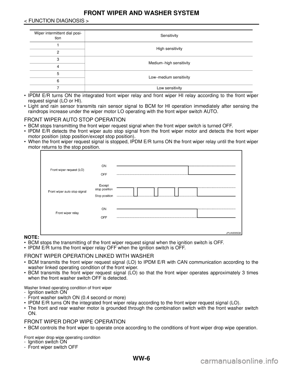
FRONT WIPER AUTO STOP OPERATION
BCM stops transmitting the front wiper request signal when the front wiper switch is turned OFF.
IPDM E/R detects the front wiper auto stop signal from the front wiper motor and detects the front wiper
motor position (stop position/except stop position).
When the front wiper request signal is stopped, IPDM E/R turns ON the front wiper relay until the front wiper
motor returns to the stop position.
NOTE:
BCM stops the transmitting of the front wiper request signal when the ignition switch is OFF.
IPDM E/R turns the front wiper relay OFF when the ignition switch is OFF.
FRONT WIPER OPERATION LINKED WITH WASHER
BCM transmits the front wiper request signal (LO) to IPDM E/R with CAN communication according to the
washer linked operating condition of the front wiper.
BCM transmits the front wiper request signal (LO) so that the front wiper operates approximately 3 times
when the front washer switch OFF is detected.
Washer linked operating condition of front wiper- Ignition switch ON
- Front washer switch ON (0.4 second or more)
IPDM E/R turns ON the integrated front wiper relay according to the front wiper request signal (LO).
The front and rear washer motor is grounded through the combination switch with the front washer switch
ON.
FRONT WIPER DROP WIPE OPERATION
BCM controls the front wiper to operate once according to the conditions of front wiper drop wipe operation.
Front wiper drop wipe operating condition- Ignition switch ON
- Front wiper switch OFF
Wiper intermittent dial posi-
tionSensitivity
1
High sensitivity
2
3
Medium−high sensitivity
4
5
Low−medium sensitivity
6
7 Low sensitivity
JPLIA0095GB
Page 5809 of 5883
FRONT WIPER AND WASHER SYSTEM
WW-7
< FUNCTION DIAGNOSIS >
C
D
E
F
G
H
I
J
K
MA
B
WW
N
O
P
- Front washer switch OFF
BCM transmits the front wiper request signal (LO) to IPDM E/R with CAN communication so that the front
wiper operate once three seconds after front wiper operation linked with washer.
IPDM E/R turns ON the integrated front wiper relay according to the front wiper request signal (LO).
FRONT WIPER FAIL−SAFE OPERATION
IPDM E/R performs the fail-safe function when the front wiper auto stop circuit is malfunctioning. Refer to
WW-52, "
FailSafe".
BCM performs fail-safe operation when light and rain sensor (if equipped) or light and rain sensor-related
systems are malfunctioning. Refer to EXL-55, "
Description".
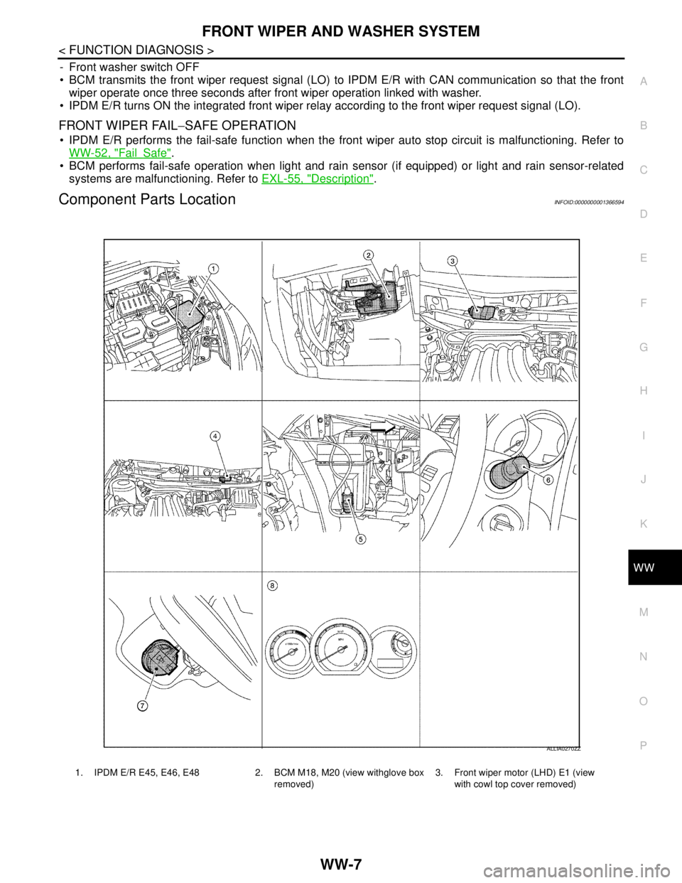
Component Parts LocationINFOID:0000000001366594
1. IPDM E/R E45, E46, E48 2. BCM M18, M20 (view withglove box
removed)3. Front wiper motor (LHD) E1 (view
with cowl top cover removed)
ALLIA0270ZZ