2007 NISSAN TIIDA fuse
[x] Cancel search: fusePage 3591 of 5883
![NISSAN TIIDA 2007 Service Repair Manual HAC-258
< COMPONENT DIAGNOSIS >[AUTO AIR CONDITIONER (W/NAVI)]
PTC HEATER CONTROL SYSTEM
The ambient sensor is attached on the radiator core support upper. It
detects ambient temperature and converts NISSAN TIIDA 2007 Service Repair Manual HAC-258
< COMPONENT DIAGNOSIS >[AUTO AIR CONDITIONER (W/NAVI)]
PTC HEATER CONTROL SYSTEM
The ambient sensor is attached on the radiator core support upper. It
detects ambient temperature and converts](/manual-img/5/57395/w960_57395-3590.png)
HAC-258
< COMPONENT DIAGNOSIS >[AUTO AIR CONDITIONER (W/NAVI)]
PTC HEATER CONTROL SYSTEM
The ambient sensor is attached on the radiator core support upper. It
detects ambient temperature and converts it into a resistance value
which is then input into the front air control.
PTC HEATER (300 WATT) : PTC Heater (300 Watt) Diagnosis ProcedureINFOID:0000000001548107
DIAGNOSTIC PROCEDURE FOR PTC SYSTEM
SYMPTOM: PTC heater system operation is malfunction.
1.CHECK POWER SUPPLY FOR PTC RELAY-1
1. Turn ignition switch ON.
2. Check voltage between PTC relay-1 harness connector E61 ter-
minals 2, 3, and ground.
Is the inspection result normal
YES >> GO TO 2.
NO >> Check power supply circuit and 10A fuse (No. 2) and 40A fusible link (No. I), located in the fuse
and fusible link box.
If fuses are OK, check harness for open circuit. Repair or replace if necessary.
If fuses are NG, replace fuse and check harness for short circuit. Repair or replace if necessary.
2.CHECK PTC RELAY-1
1. Turn ignition switch OFF.
2. Check PTC relay-1. Refer to HAC-265, "
PTC HEATER (300 WATT) : PTC Heater (300 Watt) Component
Inspection".
Is the inspection result normal
YES >> GO TO 3.
NO >> Replace PTC relay-1. Refer to XX.
3.CHECK PTC RELAY-1 OUTPUT CIRCUIT
1. Disconnect ambient sensor, PTC heater and water temperature
sensor connectors.
2. Turn temperature control dial clockwise until full hot position.
3. Turn mode control dial to foot position.
4. Start the engine.
5. Turn blower control dial to maximum speed.
6. Check continuity between PTC relay-1 harness connector E61
terminal 1 and ground.
Is the inspection result normal
YES >> GO TO 5.
AWIIA0600ZZ
Te r m i n a l s
Voltag e
(Approx.)
(+) (−)
Connector Terminal
Ground Battery voltage
PTC relay-1: E612
3
SJIA0913E
Connector Terminal
GroundContinuity
PTC relay-1: E61 1 Yes
AWIIA0455ZZ
Page 3603 of 5883
![NISSAN TIIDA 2007 Service Repair Manual HAC-270
< COMPONENT DIAGNOSIS >[AUTO AIR CONDITIONER (W/NAVI)]
PTC HEATER CONTROL SYSTEM
2.CHECK BLOWER RELAY GROUND CIRCUIT
1. Turn ignition switch OFF.
2. Check continuity between blower relay harn NISSAN TIIDA 2007 Service Repair Manual HAC-270
< COMPONENT DIAGNOSIS >[AUTO AIR CONDITIONER (W/NAVI)]
PTC HEATER CONTROL SYSTEM
2.CHECK BLOWER RELAY GROUND CIRCUIT
1. Turn ignition switch OFF.
2. Check continuity between blower relay harn](/manual-img/5/57395/w960_57395-3602.png)
HAC-270
< COMPONENT DIAGNOSIS >[AUTO AIR CONDITIONER (W/NAVI)]
PTC HEATER CONTROL SYSTEM
2.CHECK BLOWER RELAY GROUND CIRCUIT
1. Turn ignition switch OFF.
2. Check continuity between blower relay harness connector J-1
terminal 2 and ground.
Is the inspection result normal
YES >> GO TO 3.
NO >> Repair harness or connector.
3.CHECK BLOWER RELAY
1. Turn ignition switch OFF.
2. Check blower relay. Refer to XX-XX, "*****"
.
Is the inspection result normal
YES >> GO TO 4.
NO >> Replace blower relay.
4.CHECK POWER SUPPLY FOR PTC RELAY-1
1. Turn ignition switch OFF.
2. Reconnect blower relay.
3. Turn ignition switch ON.
4. Check voltage between PTC relay-1 harness connector E61 ter-
minals 2, 3, and ground.
Is the inspection result normal
YES >> GO TO 5.
NO >> Check power supply circuit and 10A and 40A fuse (No. 16 and I, located in the fuse block).
Refer to XX.
If fuses are OK, check harness for open circuit. Repair or replace if necessary.
If fuses are NG, replace fuse and check harness for short circuit. Repair or replace if necessary.
5.CHECK POWER SUPPLY FOR PTC RELAY-2
Check voltage between PTC relay-2 harness connector E62 termi-
nals 2, 3, and ground.
Is the inspection result normal
YES >> GO TO 6.
NO >> Check power supply circuit and 80A fuse (N, located in the fuse block). Refer to XX.
If fuses are OK, check harness for open circuit. Repair or replace if necessary.
If fuses are NG, replace fuse and check harness for short circuit. Repair or replace if necessary.
Connector Terminal
GroundContinuity
Blower relay: J-1 2 Yes
WJIA2264E
Te r m i n a l s
Voltag e
(Approx.)
(+) (−)
Connector Terminal
Ground Battery voltage
PTC relay-2: E612
3
AWIIA0466ZZ
Te r m i n a l s
Voltag e
(Approx.)
(+) (−)
Connector Terminal
Ground Battery voltage
PTC relay-2: E622
3
AWIIA0466ZZ
Page 3604 of 5883
![NISSAN TIIDA 2007 Service Repair Manual PTC HEATER CONTROL SYSTEM
HAC-271
< COMPONENT DIAGNOSIS >[AUTO AIR CONDITIONER (W/NAVI)]
C
D
E
F
G
H
J
K
L
MA
B
HAC
N
O
P
6.CHECK POWER SUPPLY FOR PTC RELAY-3
Check voltage between PTC relay-3 harness NISSAN TIIDA 2007 Service Repair Manual PTC HEATER CONTROL SYSTEM
HAC-271
< COMPONENT DIAGNOSIS >[AUTO AIR CONDITIONER (W/NAVI)]
C
D
E
F
G
H
J
K
L
MA
B
HAC
N
O
P
6.CHECK POWER SUPPLY FOR PTC RELAY-3
Check voltage between PTC relay-3 harness](/manual-img/5/57395/w960_57395-3603.png)
PTC HEATER CONTROL SYSTEM
HAC-271
< COMPONENT DIAGNOSIS >[AUTO AIR CONDITIONER (W/NAVI)]
C
D
E
F
G
H
J
K
L
MA
B
HAC
N
O
P
6.CHECK POWER SUPPLY FOR PTC RELAY-3
Check voltage between PTC relay-3 harness connector E61 termi-
nals 2, 3, and ground.
Is the inspection result normal
YES >> GO TO 5.
NO >> Check power supply circuit and 80A fuse (P, located in the fuse block). Refer to XX-XX.
If fuses are OK, check harness for open circuit. Repair or replace if necessary.
If fuses are NG, replace fuse and check harness for short circuit. Repair or replace if necessary.
7.CHECK PTC RELAYS
1. Turn ignition switch OFF.
2. Check PTC relay. Refer to XX-XX, "*****"
.
Is the inspection result normal
YES >> GO TO 6.
NO >> Replace inoperative PTC relay.
8.CHECK PTC RELAY-1 GROUND CIRCUIT
1. Disconnect ambient sensor, and PTC heater connectors.
2. Turn temperature control dial clockwise until full hot position.
3. Turn mode control dial to foot position.
4. Start the engine (1,000 RPM minimum).
5. Turn blower control dial to low speed.
6. Check continuity between PTC relay-1 harness connector E61
terminal 1 and ground.
Is the inspection result normal
YES >> GO TO 10.
NO >> GO TO 9.
9.CHECK CIRCUIT CONTINUITY BETWEEN PTC RELAY-1 AND BCM
1. Turn ignition switch OFF.
2. Disconnect BCM connector.
3. Check continuity between PTC relay-1 harness connector E61
(A) terminal 1 and BCM harness connector M19 (B) terminal 64.
Is the inspection result normal
YES >> Replace BCM. Refer to XXXX.
NO >> Repair harness or connector.
10.CHECK PTC RELAY-2 GROUND CIRCUIT
Te r m i n a l s
Vo l ta g e
(Approx.)
(+) (−)
Connector Terminal
Ground Battery voltage
PTC relay-3: E632
3
AWIIA0466ZZ
Connector Terminal
GroundContinuity
PTC relay-1: E61 1 Yes
AWIIA0455ZZ
AB
Continuity
Connector Terminal Connector Terminal
PTC relay-1: E61 1 BCM: M19 64 Yes
AWIIA0467ZZ
Page 3611 of 5883
![NISSAN TIIDA 2007 Service Repair Manual HAC-278
< COMPONENT DIAGNOSIS >[AUTO AIR CONDITIONER (W/NAVI)]
POWER SUPPLY AND GROUND CIRCUIT FOR CONTROLLER
A/C Auto Amp Power and Ground Diagnosis Procedure
INFOID:0000000001547370
DIAGNOSTIC PROCE NISSAN TIIDA 2007 Service Repair Manual HAC-278
< COMPONENT DIAGNOSIS >[AUTO AIR CONDITIONER (W/NAVI)]
POWER SUPPLY AND GROUND CIRCUIT FOR CONTROLLER
A/C Auto Amp Power and Ground Diagnosis Procedure
INFOID:0000000001547370
DIAGNOSTIC PROCE](/manual-img/5/57395/w960_57395-3610.png)
HAC-278
< COMPONENT DIAGNOSIS >[AUTO AIR CONDITIONER (W/NAVI)]
POWER SUPPLY AND GROUND CIRCUIT FOR CONTROLLER
A/C Auto Amp Power and Ground Diagnosis Procedure
INFOID:0000000001547370
DIAGNOSTIC PROCEDURE FOR A/C SYSTEM
SYMPTOM: A/C system does not come on.
1.CHECK POWER SUPPLY CIRCUIT FOR FRONT AIR CONTROL.
1. Turn ignition switch OFF.
2. Disconnect front air control connector.
3. Check voltage between front air control harness connector and
ground.
OK or NG
OK >> GO TO 2.
NG >> Check 10A fuses Nos. 2, 13 and 16, located in the fuse block (J/B).
If fuses are OK, check harness for open circuit. Repair or replace if necessary.
If fuses are NG, replace fuse and check harness for short circuit. Repair or replace if necessary.
2.CHECK GROUND CIRCUIT FOR FRONT AIR CONTROL
1. Turn ignition switch OFF.
2. Check continuity between front air control harness connector
and ground.
OK or NG
OK >> Replace front air control Refer to XX.
NG >> Repair or replace harness.
SJIA0877E
Terminals Ignition switch position
(+) (-)
OFF ACC ON
Connector Terminal
Ground
front air control:
M8519Battery
voltageBattery
voltageBattery
voltage
11Approx.
0VApprox.
0VBattery
voltage
18Approx.
0VApprox.
0VBattery
voltage
SJIA0878E
Connector Terminal
GroundContinuity
front air control:
M8520 Yes
SJIA0879E
Page 3726 of 5883

INSTRUMENT PANEL ASSEMBLY
IP-11
< SERVICE INFORMATION >
C
D
E
F
G
H
I
K
L
MA
B
IP
N
O
P
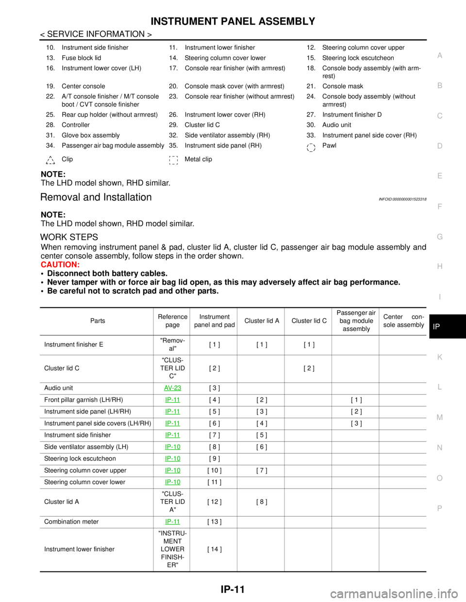
NOTE:
The LHD model shown, RHD similar.
Removal and InstallationINFOID:0000000001523318
NOTE:
The LHD model shown, RHD model similar.
WORK STEPS
When removing instrument panel & pad, cluster lid A, cluster lid C, passenger air bag module assembly and
center console assembly, follow steps in the order shown.
CAUTION:
Disconnect both battery cables.
Never tamper with or force air bag lid open, as this may adversely affect air bag performance.
Be careful not to scratch pad and other parts.
10. Instrument side finisher 11. Instrument lower finisher 12. Steering column cover upper
13. Fuse block lid 14. Steering column cover lower 15. Steering lock escutcheon
16. Instrument lower cover (LH) 17. Console rear finisher (with armrest) 18. Console body assembly (with arm-
rest)
19. Center console 20. Console mask cover (with armrest) 21. Console mask
22. A/T console finisher / M/T console
boot / CVT console finisher23. Console rear finisher (without armrest) 24. Console body assembly (without
armrest)
25. Rear cup holder (without armrest) 26. Instrument lower cover (RH) 27. Instrument finisher D
28. Controller 29. Cluster lid C 30. Audio unit
31. Glove box assembly 32. Side ventilator assembly (RH) 33. Instrument panel side cover (RH)
34. Passenger air bag module assembly 35. Instrument side panel (RH) Pawl
Clip Metal clip
PartsReference
pageInstrument
panel and padCluster lid A Cluster lid C Passenger air
bag module
assemblyCenter con-
sole assembly
Instrument finisher E"Remov-
al"[ 1 ] [ 1 ] [ 1 ]
Cluster lid C"CLUS-
TER LID
C"[ 2 ] [ 2 ]
Audio unitAV- 2 3
[ 3 ]
Front pillar garnish (LH/RH)IP-11
[ 4 ] [ 2 ] [ 1 ]
Instrument side panel (LH/RH)IP-11
[ 5 ] [ 3 ] [ 2 ]
Instrument panel side covers (LH/RH)IP-11
[ 6 ] [ 4 ] [ 3 ]
Instrument side finisherIP-11
[ 7 ] [ 5 ]
Side ventilator assembly (LH)IP-10
[ 8 ] [ 6 ]
Steering lock escutcheonIP-10
[ 9 ]
Steering column cover upperIP-10
[ 10 ] [ 7 ]
Steering column cover lowerIP-10
[ 11 ]
Cluster lid A"CLUS-
TER LID
A"[ 12 ] [ 8 ]
Combination meterIP-11
[ 13 ]
Instrument lower finisher"INSTRU-
MENT
LOWER
FINISH-
ER"[ 14 ]
Page 3727 of 5883
![NISSAN TIIDA 2007 Service Repair Manual IP-12
< SERVICE INFORMATION >
INSTRUMENT PANEL ASSEMBLY
[ ]: Number indicates step in removal procedures.
INSTRUMENT PANEL ASSEMBLY
Removal
1. Pull instrument finisher E backward by approximately 30
d NISSAN TIIDA 2007 Service Repair Manual IP-12
< SERVICE INFORMATION >
INSTRUMENT PANEL ASSEMBLY
[ ]: Number indicates step in removal procedures.
INSTRUMENT PANEL ASSEMBLY
Removal
1. Pull instrument finisher E backward by approximately 30
d](/manual-img/5/57395/w960_57395-3726.png)
IP-12
< SERVICE INFORMATION >
INSTRUMENT PANEL ASSEMBLY
[ ]: Number indicates step in removal procedures.
INSTRUMENT PANEL ASSEMBLY
Removal
1. Pull instrument finisher E backward by approximately 30
degrees while disengaging the instrument finisher E metal clips
and pawl.
Glove box assembly"GLOVE
BOX AS-
SEMBLY"[ 15 ]
Side ventilator assembly (RH)IP-10
[ 16 ] [ 4 ]
Passenger air bag module assemblySR-9
[ 17 ] [ 5 ]
Instrument upper maskIP-10
[ 18 ]
Instrument finisher DIP-10
[ 19 ]
Controller TM-674
[ 20 ]
Instrument upper panel assembly IP-11
[ 21 ]
Console mask"Remov-
al"[ 22 ] [ 1 ]
CVT, A/T console finisherIP-23
[ 23 ] [ 2 ]
M/T console bootIP-23
[ 23 ] [ 2 ]
Console rear finisherIP-23
[ 24 ] [ 3 ]
Console mask cover (with arm rest)IP-23
[ 25 ] [ 4 ]
Rear cup holder (without arm rest)IP-23
[ 25 ] [ 4 ]
Console body assemblyIP-23
[ 26 ] [ 5 ]
Instrument lower cover (LH/RH)"INSTRU-
MENT
LOWER
FINISH-
ER"[ 27 ] [ 6 ]
Center console assembly"CEN-
TER
CON-
SOLE AS-
SEMBLY"[ 28 ] [ 7 ]
Fuse block lidIP-10
[ 29 ]
Lighting and turn signal switchEXL-101
[ 30 ]
Wiper & washer switchWW-76
[ 31 ]
Instrument panel & padIP-10
[ 32 ] PartsReference
pageInstrument
panel and padCluster lid A Cluster lid C Passenger air
bag module
assemblyCenter con-
sole assembly
WIIA1224E
Page 3730 of 5883

INSTRUMENT PANEL ASSEMBLY
IP-15
< SERVICE INFORMATION >
C
D
E
F
G
H
I
K
L
MA
B
IP
N
O
P
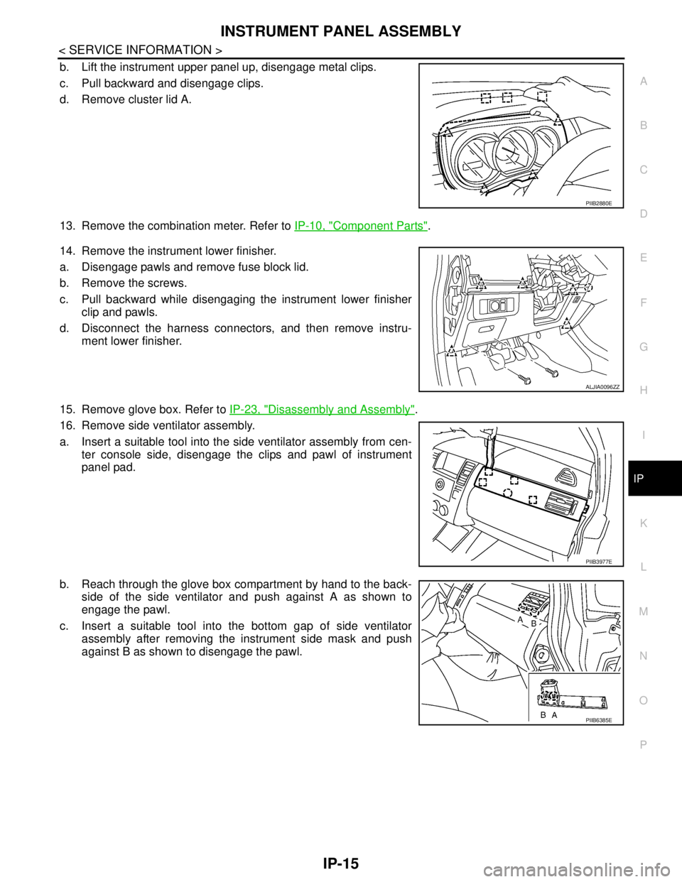
b. Lift the instrument upper panel up, disengage metal clips.
c. Pull backward and disengage clips.
d. Remove cluster lid A.
13. Remove the combination meter. Refer to IP-10, "
Component Parts".
14. Remove the instrument lower finisher.
a. Disengage pawls and remove fuse block lid.
b. Remove the screws.
c. Pull backward while disengaging the instrument lower finisher
clip and pawls.
d. Disconnect the harness connectors, and then remove instru-
ment lower finisher.
15. Remove glove box. Refer to IP-23, "
Disassembly and Assembly".
16. Remove side ventilator assembly.
a. Insert a suitable tool into the side ventilator assembly from cen-
ter console side, disengage the clips and pawl of instrument
panel pad.
b. Reach through the glove box compartment by hand to the back-
side of the side ventilator and push against A as shown to
engage the pawl.
c. Insert a suitable tool into the bottom gap of side ventilator
assembly after removing the instrument side mask and push
against B as shown to disengage the pawl.
PIIB2880E
ALJIA0096ZZ
PIIB3977E
PIIB6385E
Page 3737 of 5883

IP-22
< SERVICE INFORMATION >
INSTRUMENT PANEL ASSEMBLY
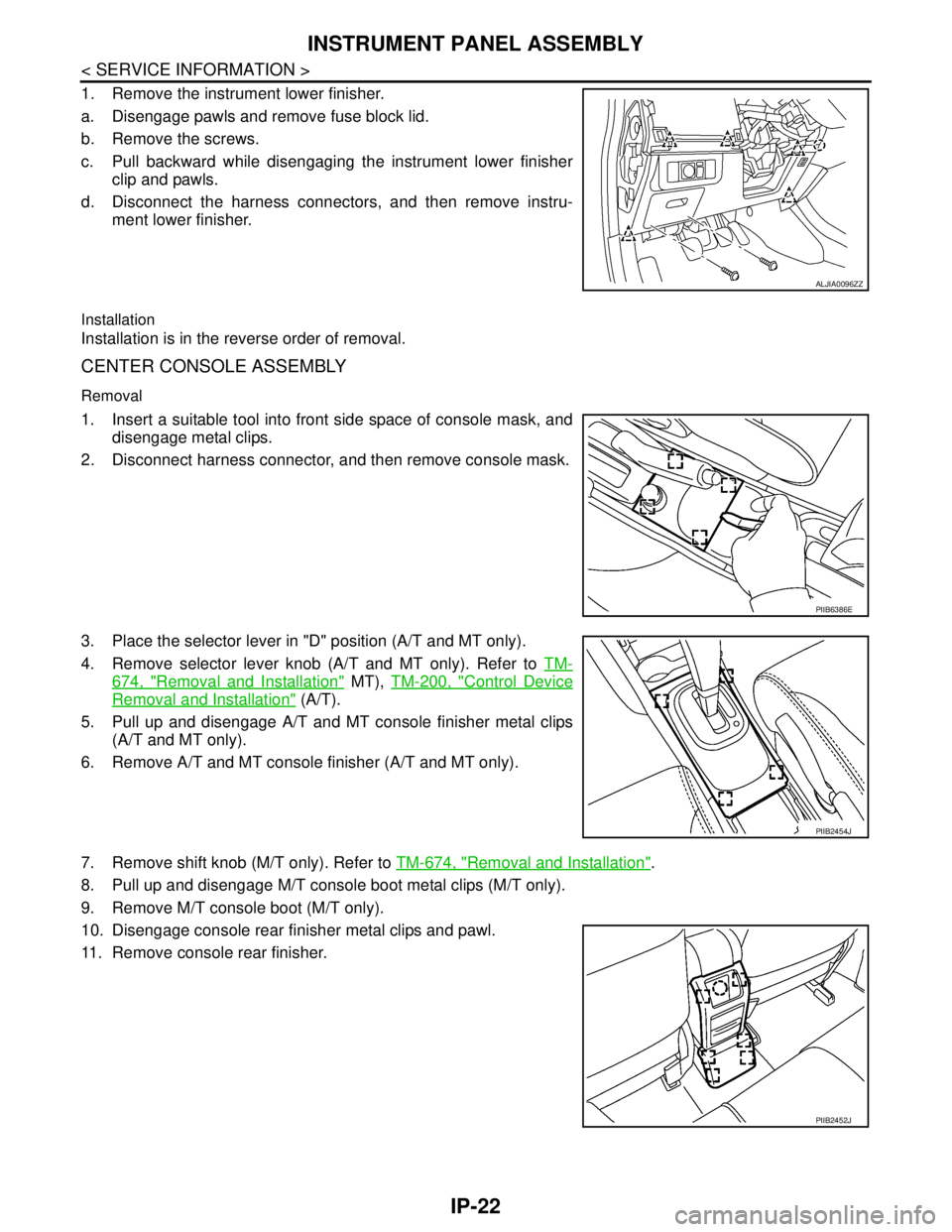
1. Remove the instrument lower finisher.
a. Disengage pawls and remove fuse block lid.
b. Remove the screws.
c. Pull backward while disengaging the instrument lower finisher
clip and pawls.
d. Disconnect the harness connectors, and then remove instru-
ment lower finisher.
Installation
Installation is in the reverse order of removal.
CENTER CONSOLE ASSEMBLY
Removal
1. Insert a suitable tool into front side space of console mask, and
disengage metal clips.
2. Disconnect harness connector, and then remove console mask.
3. Place the selector lever in "D" position (A/T and MT only).
4. Remove selector lever knob (A/T and MT only). Refer to TM-
674, "Removal and Installation" MT), TM-200, "Control Device
Removal and Installation" (A/T).
5. Pull up and disengage A/T and MT console finisher metal clips
(A/T and MT only).
6. Remove A/T and MT console finisher (A/T and MT only).
7. Remove shift knob (M/T only). Refer to TM-674, "
Removal and Installation".
8. Pull up and disengage M/T console boot metal clips (M/T only).
9. Remove M/T console boot (M/T only).
10. Disengage console rear finisher metal clips and pawl.
11. Remove console rear finisher.
ALJIA0096ZZ
PIIB6386E
PIIB2454J
PIIB2452J