2007 NISSAN TIIDA fuse
[x] Cancel search: fusePage 3050 of 5883
PARKING LAMP CIRCUIT
EXL-49
< COMPONENT DIAGNOSIS >
C
D
E
F
G
H
I
J
K
MA
B
EXL
N
O
P
WITHOUT DAYTIME LIGHT SYSTEM : Diagnosis ProcedureINFOID:0000000001527577
1.CHECK PARKING LAMP FUSE
1. Turn the ignition switch OFF.
2. Check that the following fuse is not open.
Is the fuse open?
YES >> Repair the harness and replace the fuse.
NO >> GO TO 2
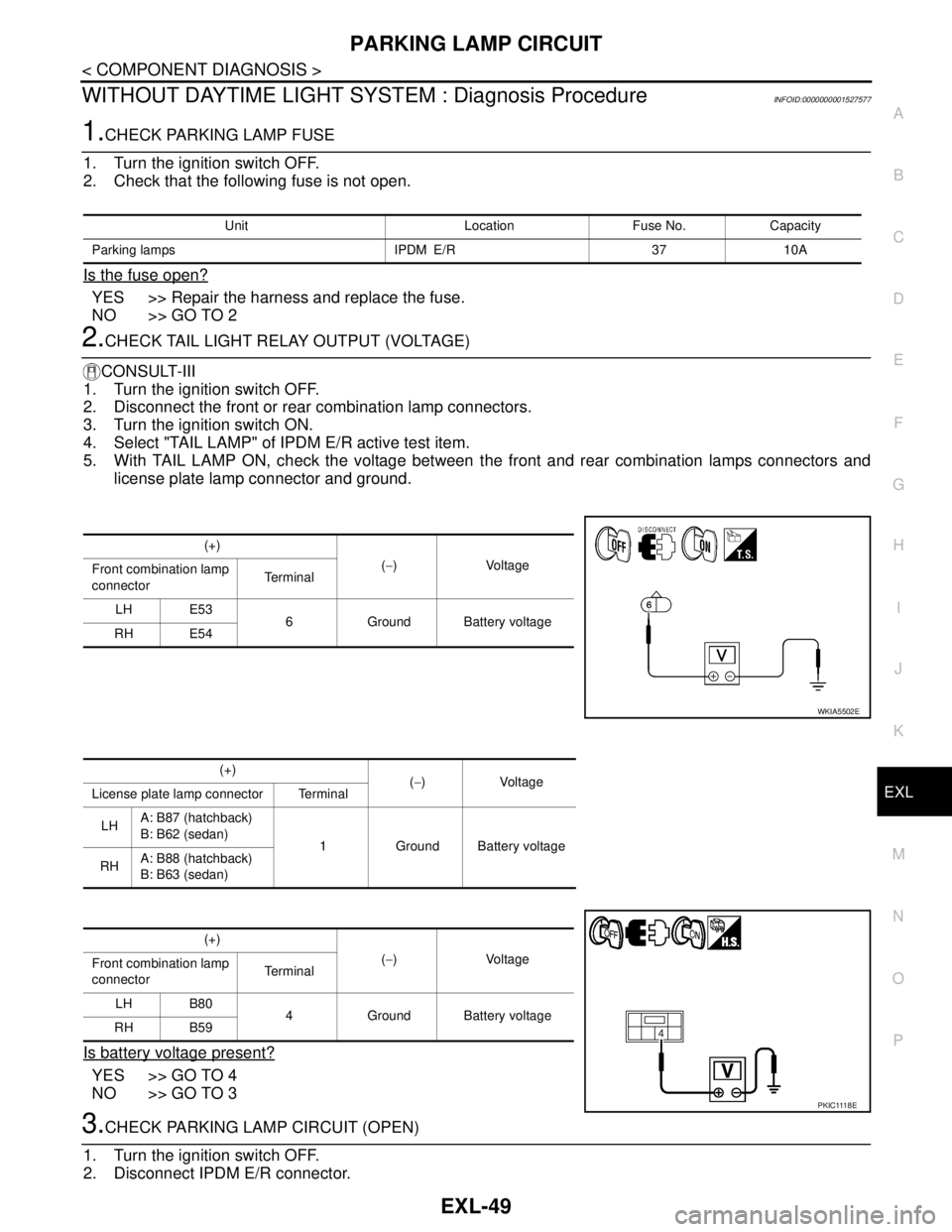
2.CHECK TAIL LIGHT RELAY OUTPUT (VOLTAGE)
CONSULT-III
1. Turn the ignition switch OFF.
2. Disconnect the front or rear combination lamp connectors.
3. Turn the ignition switch ON.
4. Select "TAIL LAMP" of IPDM E/R active test item.
5. With TAIL LAMP ON, check the voltage between the front and rear combination lamps connectors and
license plate lamp connector and ground.
Is battery voltage present?
YES >> GO TO 4
NO >> GO TO 3
3.CHECK PARKING LAMP CIRCUIT (OPEN)
1. Turn the ignition switch OFF.
2. Disconnect IPDM E/R connector.
Unit Location Fuse No. Capacity
Parking lamps IPDM E/R 37 10A
(+)
(−)Voltage
Front combination lamp
connectorTe r m i n a l
LH E53
6 Ground Battery voltage
RH E54
WKIA5502E
(+)
(−)Voltage
License plate lamp connector Terminal
LHA: B87 (hatchback)
B: B62 (sedan)
1 Ground Battery voltage
RHA: B88 (hatchback)
B: B63 (sedan)
(+)
(−)Voltage
Front combination lamp
connectorTe r m i n a l
LH B80
4 Ground Battery voltage
RH B59
P K I C 111 8 E
Page 3074 of 5883
EXTERIOR LIGHTING SYSTEM SYMPTOMS
EXL-73
< SYMPTOM DIAGNOSIS >
C
D
E
F
G
H
I
J
K
MA
B
EXL
N
O
P
SYMPTOM DIAGNOSIS
EXTERIOR LIGHTING SYSTEM SYMPTOMS
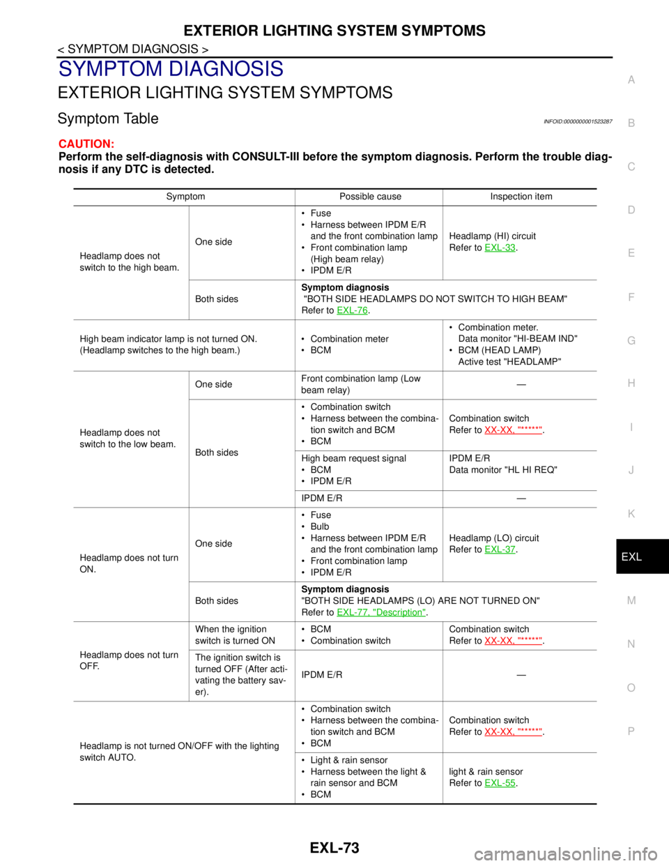
Symptom TableINFOID:0000000001523287
CAUTION:
Perform the self-diagnosis with CONSULT-III before the symptom diagnosis. Perform the trouble diag-
nosis if any DTC is detected.
Symptom Possible cause Inspection item
Headlamp does not
switch to the high beam.One sideFuse
Harness between IPDM E/R
and the front combination lamp
Front combination lamp
(High beam relay)
IPDM E/RHeadlamp (HI) circuit
Refer to EXL-33
.
Both sidesSymptom diagnosis
"BOTH SIDE HEADLAMPS DO NOT SWITCH TO HIGH BEAM"
Refer to EXL-76
.
High beam indicator lamp is not turned ON.
(Headlamp switches to the high beam.) Combination meter
BCM Combination meter.
Data monitor "HI-BEAM IND"
BCM (HEAD LAMP)
Active test "HEADLAMP"
Headlamp does not
switch to the low beam.One sideFront combination lamp (Low
beam relay)—
Both sides Combination switch
Harness between the combina-
tion switch and BCM
BCMCombination switch
Refer to XX-XX, "*****"
.
High beam request signal
BCM
IPDM E/RIPDM E/R
Data monitor "HL HI REQ"
IPDM E/R —
Headlamp does not turn
ON.One sideFuse
Bulb
Harness between IPDM E/R
and the front combination lamp
Front combination lamp
IPDM E/RHeadlamp (LO) circuit
Refer to EXL-37
.
Both sidesSymptom diagnosis
"BOTH SIDE HEADLAMPS (LO) ARE NOT TURNED ON"
Refer to EXL-77, "
Description".
Headlamp does not turn
OFF.When the ignition
switch is turned ONBCM
Combination switchCombination switch
Refer to XX-XX, "*****"
.
The ignition switch is
turned OFF (After acti-
vating the battery sav-
er).IPDM E/R —
Headlamp is not turned ON/OFF with the lighting
switch AUTO. Combination switch
Harness between the combina-
tion switch and BCM
BCMCombination switch
Refer to XX-XX, "*****"
.
Light & rain sensor
Harness between the light &
rain sensor and BCM
BCMlight & rain sensor
Refer to EXL-55
.
Page 3075 of 5883

EXL-74
< SYMPTOM DIAGNOSIS >
EXTERIOR LIGHTING SYSTEM SYMPTOMS
Daytime light system does not activate. Either high beam bulb
Parking brake switch
Combination switch
BCM
IPDM E/R
Daytime light relay
Harness between IPDM E/R
and daytime light relay.Daytime light system description.
Refer to XX-XX, "*****"
.
Front fog lamp is not
turned ON.One side Front fog lamp bulb
Harness between IPDM E/R
and the front combination lamp
Front combination lamp
IPDM E/RFront fog lamp circuit
Refer to EXL-41
.
Both sideSymptom diagnosis
"BOTH SIDE FRONT FOG LAMPS ARE NOT TURNED ON"
Refer to EXL-79
.
Parking lamp is not turned
ON.One sideFuse
Parking lamp bulb
Harness between IPDM E/R
and the front/rear combination
lamp
Front/rear combination lamp
IPDM E/RParking lamp circuit
Refer to EXL-46
.
Both sidesSymptom diagnosis
"PARKING, LICENSE PLATE AND TAIL LAMPS ARE NOT TURNED
ON"
Refer to EXL-78
.
Turn signal lamp does not
blink.Indicator lamp is nor-
mal.
(The applicable side
performs the high flash-
er activation). Harness between BCM and
each turn signal lamp
Turn signal lamp bulb
Door mirror (if equipped with
turn signals in the door mirrors)Turn signal lamp circuit
Refer to EXL-52
.
Turn signal indicator lamp
does not blink.One side Combination meter —
Both sides
(Always) Turn signal indicator lamp sig-
nal
Combination meter
BCM Combination meter.
Data monitor "TURN IND"
BCM (FLASHER)
Active test "FLASHER"
Both sides
(Does blink when acti-
vating the hazard warn-
ing lamp with the
ignition switch OFF) The combination meter power
supply and the ground circuit
Combination meterCombination meter
Power supply and the ground circuit
Refer to XX-XX, "*****"
. Symptom Possible cause Inspection item
Page 3206 of 5883
GI-12
< HOW TO USE THIS MANUAL >
HOW TO USE THIS MANUAL
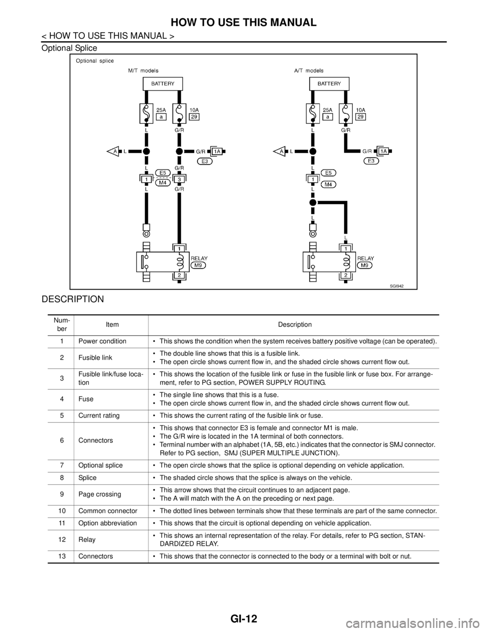
Optional Splice
DESCRIPTION
SGI942
Num-
berItem Description
1 Power condition This shows the condition when the system receives battery positive voltage (can be operated).
2Fusible link The double line shows that this is a fusible link.
The open circle shows current flow in, and the shaded circle shows current flow out.
3Fusible link/fuse loca-
tion This shows the location of the fusible link or fuse in the fusible link or fuse box. For arrange-
ment, refer to PG section, POWER SUPPLY ROUTING.
4Fuse The single line shows that this is a fuse.
The open circle shows current flow in, and the shaded circle shows current flow out.
5 Current rating This shows the current rating of the fusible link or fuse.
6 Connectors This shows that connector E3 is female and connector M1 is male.
The G/R wire is located in the 1A terminal of both connectors.
Terminal number with an alphabet (1A, 5B, etc.) indicates that the connector is SMJ connector.
Refer to PG section, SMJ (SUPER MULTIPLE JUNCTION).
7 Optional splice The open circle shows that the splice is optional depending on vehicle application.
8 Splice The shaded circle shows that the splice is always on the vehicle.
9 Page crossing This arrow shows that the circuit continues to an adjacent page.
The A will match with the A on the preceding or next page.
10 Common connector The dotted lines between terminals show that these terminals are part of the same connector.
11 Option abbreviation This shows that the circuit is optional depending on vehicle application.
12 Relay This shows an internal representation of the relay. For details, refer to PG section, STAN-
DARDIZED RELAY.
13 Connectors This shows that the connector is connected to the body or a terminal with bolt or nut.
Page 3207 of 5883

HOW TO USE THIS MANUAL
GI-13
< HOW TO USE THIS MANUAL >
C
D
E
F
G
H
I
J
K
L
MB
GI
N
O
P
Harness Indication
14 Wire color This shows a code for the color of the wire.
B = Black
W = White
R = Red
G = Green
L = Blue
Y = Yellow
LG = Light GreenBR = Brown
OR or O = Orange
P = Pink
PU or V (Violet) = Purple
GY or GR = Gray
SB = Sky Blue
CH = Dark Brown
DG = Dark Green
When the wire color is striped, the base color is given first, followed by the stripe color as shown
below:
Example: L/W = Blue with White Stripe
15 Option description This shows a description of the option abbreviation used on the page.
16 Switch This shows that continuity exists between terminals 1 and 2 when the switch is in the A posi-
tion. Continuity exists between terminals 1 and 3 when the switch is in the B position.
17 Assembly parts Connector terminal in component shows that it is a harness incorporated assembly.
18 Cell code This identifies each page of the wiring diagram by section, system and wiring diagram page
number.
19 Current flow arrow Arrow indicates electric current flow, especially where the direction of standard flow (vertically
downward or horizontally from left to right) is difficult to follow.
A double arrow “ ” shows that current can flow in either direction depending on circuit
operation.
20 System branch This shows that the system branches to another system identified by cell code (section and
system).
21 Page crossing This arrow shows that the circuit continues to another page identified by cell code.
The C will match with the C on another page within the system other than the next or preceding
pages.
22 Shielded line The line enclosed by broken line circle shows shield wire.
23Component box in
wave line This shows that another part of the component is also shown on another page (indicated by
wave line) within the system.
24 Component name This shows the name of a component.
25 Connector number This shows the connector number.
The letter shows which harness the connector is located in.
Example: M: main harness. For detail and to locate the connector, refer to PG section "Main
Harness", “Harness Layout”. A coordinate grid is included for complex harnesses to aid in lo-
cating connectors.
26 Ground (GND) The line spliced and grounded under wire color shows that ground line is spliced at the ground-
ed connector.
27 Ground (GND) This shows the ground connection. For detailed ground distribution information, refer to
"Ground Distribution" in PG section.
28 Connector views This area shows the connector faces of the components in the wiring diagram on the page.
29 Common component Connectors enclosed in broken line show that these connectors belong to the same compo-
nent.
30 Connector color This shows a code for the color of the connector. For code meaning, refer to wire color codes,
Number 14 of this chart.
31Fusible link and fuse
box This shows the arrangement of fusible link(s) and fuse(s), used for connector views of "POW-
ER SUPPLY ROUTING" in PG section.
The open square shows current flow in, and the shaded square shows current flow out.
32 Reference area This shows that more information on the Super Multiple Junction (SMJ) and Joint Connectors
(J/C) exists on the PG section. Refer to "Reference Area" for details. Num-
berItem Description
Page 3217 of 5883

HOW TO READ WIRING DIAGRAMS
GI-23
< HOW TO USE THIS MANUAL >
C
D
E
F
G
H
I
J
K
L
MB
GI
N
O
P
DescriptionINFOID:0000000001691462
SWITCH POSITIONS
Switches are shown in wiring diagrams as if the vehicle is in the “normal” condition.
A vehicle is in the “normal” condition when:
Number Item Description
1 Power supply This means the power supply of fusible link or fuse.
2 Fusible link “X” means the fusible link.
3Number of fusible link/
fuse This means the number of fusible link or fuse location.
4 Fuse “/” means the fuse.
5Current rating of fus-
ible link/fuse This means the current rating of the fusible link or fuse.
6 Optional splice The open circle shows that the splice is optional depending on vehicle application.
7 Connector number The letter shows which harness the connector is located in.
Example “M”: main harness. For detail and to locate the connector, refer to ELECTRICAL
UNIT LOCATION in PG, HARNESS LAYOUT in PG.
8Splice
The shaded circle “ ” means the splice.
9 Page crossing This circuit continues to an adjacent page.
10 Option abbreviation
This means the vehicle specifications which layouts the circuit between “ ”.
11 Relay This shows an internal representation of the relay.
12 Option description This shows a description of the option abbreviation used on the page.
13 Switch This shows that continuity exists between terminals 1 and 2 when the switch is in the A
position. Continuity exists between terminals 1 and 3 when the switch is in the B position.
14 Circuit (Wiring) This means the wiring.
15 System branch This shows that the circuit is branched to other systems.
16 Shielded line The line enclosed by broken line circle shows shield wire.
17 Component name This shows the name of a component.
18 Ground (GND) This shows the ground connection.
19 Connector This means the connector information.
This unit-side is described by the connector symbols.
20 Connectors This means that a transmission line bypasses two connectors or more.
21 Wire color This shows a code for the color of the wire.
B = Black
W = White
R = Red
G = Green
L = Blue
Y = Yellow
LG = Light GreenBR = Brown
OR or O = Orange
P = Pink
PU or V (Violet) = Purple
GY or GR = Gray
SB = Sky Blue
CH = Dark Brown
DG = Dark Green
When the wire color is striped, the base color is given first, followed by the stripe color as
shown below:
Example: L/W = Blue with White Stripe
22 Terminal number This means the terminal number of a connector.
Page 3252 of 5883
GI-58
< BASIC INSPECTION >
SERVICE INFORMATION FOR ELECTRICAL INCIDENT
Circuit Inspection
INFOID:0000000001691471
DESCRIPTION
In general, testing electrical circuits is an easy task if it is approached in a logical and organized method.
Before beginning it is important to have all available information on the system to be tested. Also, get a thor-
ough understanding of system operation. Then you will be able to use the appropriate equipment and follow
the correct test procedure.
You may have to simulate vehicle vibrations while testing electrical components. Gently shake the wiring
harness or electrical component to do this.
NOTE:
Refer to GI-52, "
How to Check Terminal" to probe or check terminal.
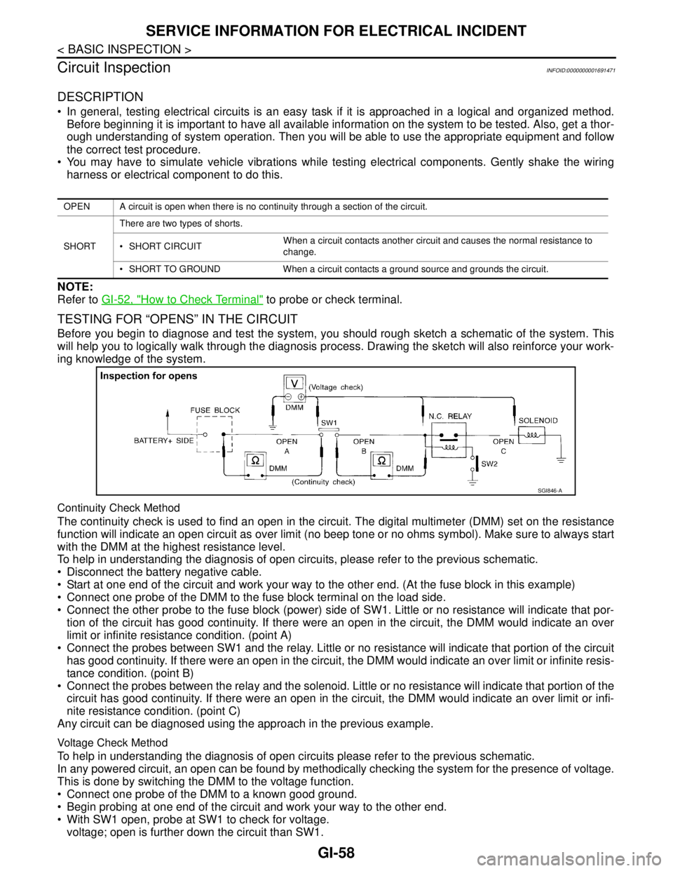
TESTING FOR “OPENS” IN THE CIRCUIT
Before you begin to diagnose and test the system, you should rough sketch a schematic of the system. This
will help you to logically walk through the diagnosis process. Drawing the sketch will also reinforce your work-
ing knowledge of the system.
Continuity Check Method
The continuity check is used to find an open in the circuit. The digital multimeter (DMM) set on the resistance
function will indicate an open circuit as over limit (no beep tone or no ohms symbol). Make sure to always start
with the DMM at the highest resistance level.
To help in understanding the diagnosis of open circuits, please refer to the previous schematic.
Disconnect the battery negative cable.
Start at one end of the circuit and work your way to the other end. (At the fuse block in this example)
Connect one probe of the DMM to the fuse block terminal on the load side.
Connect the other probe to the fuse block (power) side of SW1. Little or no resistance will indicate that por-
tion of the circuit has good continuity. If there were an open in the circuit, the DMM would indicate an over
limit or infinite resistance condition. (point A)
Connect the probes between SW1 and the relay. Little or no resistance will indicate that portion of the circuit
has good continuity. If there were an open in the circuit, the DMM would indicate an over limit or infinite resis-
tance condition. (point B)
Connect the probes between the relay and the solenoid. Little or no resistance will indicate that portion of the
circuit has good continuity. If there were an open in the circuit, the DMM would indicate an over limit or infi-
nite resistance condition. (point C)
Any circuit can be diagnosed using the approach in the previous example.
Voltage Check Method
To help in understanding the diagnosis of open circuits please refer to the previous schematic.
In any powered circuit, an open can be found by methodically checking the system for the presence of voltage.
This is done by switching the DMM to the voltage function.
Connect one probe of the DMM to a known good ground.
Begin probing at one end of the circuit and work your way to the other end.
With SW1 open, probe at SW1 to check for voltage.
voltage; open is further down the circuit than SW1.
OPEN A circuit is open when there is no continuity through a section of the circuit.
SHORTThere are two types of shorts.
SHORT CIRCUITWhen a circuit contacts another circuit and causes the normal resistance to
change.
SHORT TO GROUND When a circuit contacts a ground source and grounds the circuit.
SGI846-A
Page 3253 of 5883
SERVICE INFORMATION FOR ELECTRICAL INCIDENT
GI-59
< BASIC INSPECTION >
C
D
E
F
G
H
I
J
K
L
MB
GI
N
O
P
no voltage; open is between fuse block and SW1 (point A).
Close SW1 and probe at relay.
voltage; open is further down the circuit than the relay.
no voltage; open is between SW1 and relay (point B).
Close the relay and probe at the solenoid.
voltage; open is further down the circuit than the solenoid.
no voltage; open is between relay and solenoid (point C).
Any powered circuit can be diagnosed using the approach in the previous example.
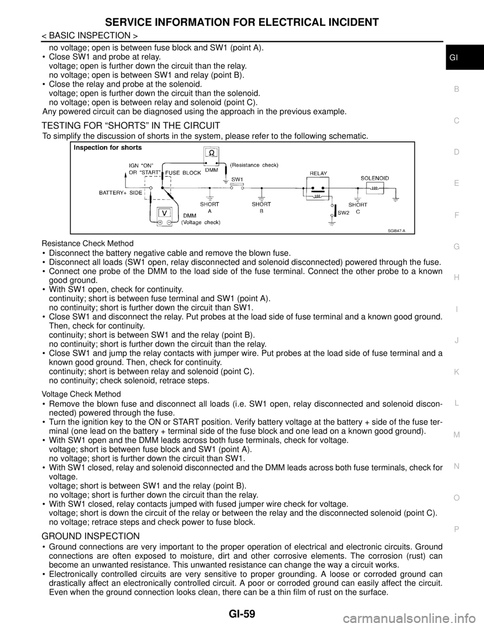
TESTING FOR “SHORTS” IN THE CIRCUIT
To simplify the discussion of shorts in the system, please refer to the following schematic.
Resistance Check Method
Disconnect the battery negative cable and remove the blown fuse.
Disconnect all loads (SW1 open, relay disconnected and solenoid disconnected) powered through the fuse.
Connect one probe of the DMM to the load side of the fuse terminal. Connect the other probe to a known
good ground.
With SW1 open, check for continuity.
continuity; short is between fuse terminal and SW1 (point A).
no continuity; short is further down the circuit than SW1.
Close SW1 and disconnect the relay. Put probes at the load side of fuse terminal and a known good ground.
Then, check for continuity.
continuity; short is between SW1 and the relay (point B).
no continuity; short is further down the circuit than the relay.
Close SW1 and jump the relay contacts with jumper wire. Put probes at the load side of fuse terminal and a
known good ground. Then, check for continuity.
continuity; short is between relay and solenoid (point C).
no continuity; check solenoid, retrace steps.
Voltage Check Method
Remove the blown fuse and disconnect all loads (i.e. SW1 open, relay disconnected and solenoid discon-
nected) powered through the fuse.
Turn the ignition key to the ON or START position. Verify battery voltage at the battery + side of the fuse ter-
minal (one lead on the battery + terminal side of the fuse block and one lead on a known good ground).
With SW1 open and the DMM leads across both fuse terminals, check for voltage.
voltage; short is between fuse block and SW1 (point A).
no voltage; short is further down the circuit than SW1.
With SW1 closed, relay and solenoid disconnected and the DMM leads across both fuse terminals, check for
voltage.
voltage; short is between SW1 and the relay (point B).
no voltage; short is further down the circuit than the relay.
With SW1 closed, relay contacts jumped with fused jumper wire check for voltage.
voltage; short is down the circuit of the relay or between the relay and the disconnected solenoid (point C).
no voltage; retrace steps and check power to fuse block.
GROUND INSPECTION
Ground connections are very important to the proper operation of electrical and electronic circuits. Ground
connections are often exposed to moisture, dirt and other corrosive elements. The corrosion (rust) can
become an unwanted resistance. This unwanted resistance can change the way a circuit works.
Electronically controlled circuits are very sensitive to proper grounding. A loose or corroded ground can
drastically affect an electronically controlled circuit. A poor or corroded ground can easily affect the circuit.
Even when the ground connection looks clean, there can be a thin film of rust on the surface.
SGI847-A