2007 NISSAN TIIDA oil temperature
[x] Cancel search: oil temperaturePage 4382 of 5883

MWI
IPDM E/R (INTELLIGENT POWER DISTRIBUTION MODULE ENGINE ROOM)
MWI-75
< ECU DIAGNOSIS >
C
D
E
F
G
H
I
J
K
L
MB A
O
P
IPDM E/R (INTELLIGENT POWER DISTRIBUTION MODULE ENGINE
ROOM)
Reference ValueINFOID:0000000001713125
VALUES ON THE DIAGNOSIS TOOL
Monitor Item Condition Value/Status
MOTOR FAN REQ Engine idle speedChanges depending on engine
coolant temperature, air conditioner
operation status, vehicle speed,
etc.0 - 100 %
A/C COMP REQA/C switch OFF OFF
A/C switch ON ON
TA I L & C L R R E QLighting switch OFF OFF
Lighting switch 1ST, 2ND, HI or AUTO (Light is illuminated) ON
HL LO REQLighting switch OFF OFF
Lighting switch 2ND HI or AUTO (Light is illuminated) ON
HL HI REQLighting switch OFF OFF
Lighting switch HI ON
FR FOG REQLighting switch 2ND or AUTO (Light
is illuminated)Front fog lamp switch OFF OFF
Front fog lamp switch ON
Daytime light activated ON
HL WASHER REQNOTE:
This item is displayed, but cannot be monitored.OFF
FR WIP REQ Ignition switch ONFront wiper switch OFF STOP
Front wiper switch INT 1LOW
Front wiper switch LO LOW
Front wiper switch HI HI
WIP AUTO STOP Ignition switch ONFront wiper stop position STOP P
Any position other than front wiper
stop positionACT P
WIP PROT Ignition switch ONFront wiper operates normally OFF
Front wiper stops at fail-safe opera-
tionBLOCK
ST RLY REQIgnition switch OFF or ACC OFF
Ignition switch START ON
IGN RLYIgnition switch OFF or ACC OFF
Ignition switch ON ON
RR DEF REQRear defogger switch OFF OFF
Rear defogger switch ON ON
OIL P SWIgnition switch OFF, ACC or engine running OPEN
Ignition switch ON CLOSE
DTRL REQNOTE:
This item is displayed, but cannot be monitored.OFF
HOOD SWNOTE:
This item is displayed, but cannot be monitored.OFF
Page 4426 of 5883
![NISSAN TIIDA 2007 Service Repair Manual PCS-12
< FUNCTION DIAGNOSIS >[IPDM E/R]
DIAGNOSIS SYSTEM (IPDM E/R)
IPDM E/R starts the auto active test with the door switch signals transmitted by BCM via CAN communica-
tion. Therefore, the CAN c NISSAN TIIDA 2007 Service Repair Manual PCS-12
< FUNCTION DIAGNOSIS >[IPDM E/R]
DIAGNOSIS SYSTEM (IPDM E/R)
IPDM E/R starts the auto active test with the door switch signals transmitted by BCM via CAN communica-
tion. Therefore, the CAN c](/manual-img/5/57395/w960_57395-4425.png)
PCS-12
< FUNCTION DIAGNOSIS >[IPDM E/R]
DIAGNOSIS SYSTEM (IPDM E/R)
IPDM E/R starts the auto active test with the door switch signals transmitted by BCM via CAN communica-
tion. Therefore, the CAN communication line between IPDM E/R and BCM is considered normal if the auto
active test starts successfully.
The auto active test facilitates troubleshooting if any systems controlled by IPDM E/R cannot be operated.
Diagnosis chart in auto active test mode
Symptom Inspection contents Possible cause
Oil pressure low warning indicator does not operatePerform auto active test.
Does the oil pressure low/
coolant temperature high
warning indicator operate?YES IPDM E/R signal input cir-
cuit
ECM signal input circuit
CAN communication signal
between ECM and combi-
nation meter
NO CAN communication signal
between IPDM E/R, BCM
and combination meter
Rear window defogger does not operatePerform auto active test.
Does the rear window defog-
ger operate?YES BCM signal input circuit
NO Harness or connector be-
tween A/C and AV switch
assembly and AV control
unit
CAN communication signal
between BCM and IPDM E/
R
Any of the following components do not operate
Front wipers
Tail lamps
License plate lamps
Parking lamps
Front fog lamps
Headlamps (Hi, Lo)Perform auto active test.
Does the applicable system
operate?YES BCM signal input system
NO Lamp or front wiper motor
malfunction
Lamp or front wiper motor
ground circuit
Harness or connector be-
tween IPDM E/R and appli-
cable system
IPDM E/R (integrated relay
malfunction)
A/C compressor does not operatePerform auto active test.
Does the A/C compressor op-
erate?YES BCM signal input circuit
CAN communication signal
between BCM and ECM
CAN communication signal
between ECM and IPDM E/
R
NO Magnetic clutch malfunction
Harness or connector be-
tween IPDM E/R and mag-
netic clutch
IPDM E/R (integrated relay
malfunction)
Cooling fan does not operatePerform auto active test.
Does the cooling fan operate?YES ECM signal input circuit
CAN communication signal
between ECM and IPDM E/
R
NO Cooling fan motor malfunc-
tion
Harness or connector be-
tween IPDM E/R and cool-
ing fan
IPDM E/R (integrated relay
malfunction)
Page 4431 of 5883
![NISSAN TIIDA 2007 Service Repair Manual PCS
IPDM E/R (INTELLIGENT POWER DISTRIBUTION MODULE ENGINE ROOM)
PCS-17
< ECU DIAGNOSIS >[IPDM E/R]
C
D
E
F
G
H
I
J
K
L B A
O
P N
ECU DIAGNOSIS
IPDM E/R (INTELLIGENT POWER DISTRIBUTION MODULE ENGINE
R NISSAN TIIDA 2007 Service Repair Manual PCS
IPDM E/R (INTELLIGENT POWER DISTRIBUTION MODULE ENGINE ROOM)
PCS-17
< ECU DIAGNOSIS >[IPDM E/R]
C
D
E
F
G
H
I
J
K
L B A
O
P N
ECU DIAGNOSIS
IPDM E/R (INTELLIGENT POWER DISTRIBUTION MODULE ENGINE
R](/manual-img/5/57395/w960_57395-4430.png)
PCS
IPDM E/R (INTELLIGENT POWER DISTRIBUTION MODULE ENGINE ROOM)
PCS-17
< ECU DIAGNOSIS >[IPDM E/R]
C
D
E
F
G
H
I
J
K
L B A
O
P N
ECU DIAGNOSIS
IPDM E/R (INTELLIGENT POWER DISTRIBUTION MODULE ENGINE
ROOM)
Reference ValueINFOID:0000000001697595
VALUES ON THE DIAGNOSIS TOOL
Monitor Item Condition Value/Status
MOTOR FAN REQ Engine idle speedChanges depending on engine
coolant temperature, air conditioner
operation status, vehicle speed,
etc.0 - 100 %
A/C COMP REQA/C switch OFF OFF
A/C switch ON ON
TA I L & C L R R E QLighting switch OFF OFF
Lighting switch 1ST, 2ND, HI or AUTO (Light is illuminated) ON
HL LO REQLighting switch OFF OFF
Lighting switch 2ND HI or AUTO (Light is illuminated) ON
HL HI REQLighting switch OFF OFF
Lighting switch HI ON
FR FOG REQLighting switch 2ND or AUTO (Light
is illuminated)Front fog lamp switch OFF OFF
Front fog lamp switch ON
Daytime light activated ON
HL WASHER REQNOTE:
This item is displayed, but cannot be monitored.OFF
FR WIP REQ Ignition switch ONFront wiper switch OFF STOP
Front wiper switch INT 1LOW
Front wiper switch LO LOW
Front wiper switch HI HI
WIP AUTO STOP Ignition switch ONFront wiper stop position STOP P
Any position other than front wiper
stop positionACT P
WIP PROT Ignition switch ONFront wiper operates normally OFF
Front wiper stops at fail-safe opera-
tionBLOCK
ST RLY REQIgnition switch OFF or ACC OFF
Ignition switch START ON
IGN RLYIgnition switch OFF or ACC OFF
Ignition switch ON ON
RR DEF REQRear defogger switch OFF OFF
Rear defogger switch ON ON
OIL P SWIgnition switch OFF, ACC or engine running OPEN
Ignition switch ON CLOSE
DTRL REQNOTE:
This item is displayed, but cannot be monitored.OFF
HOOD SWNOTE:
This item is displayed, but cannot be monitored.OFF
Page 4747 of 5883

SR-4
< ON-VEHICLE REPAIR >
DRIVER AIR BAG MODULE
ON-VEHICLE REPAIR
DRIVER AIR BAG MODULE
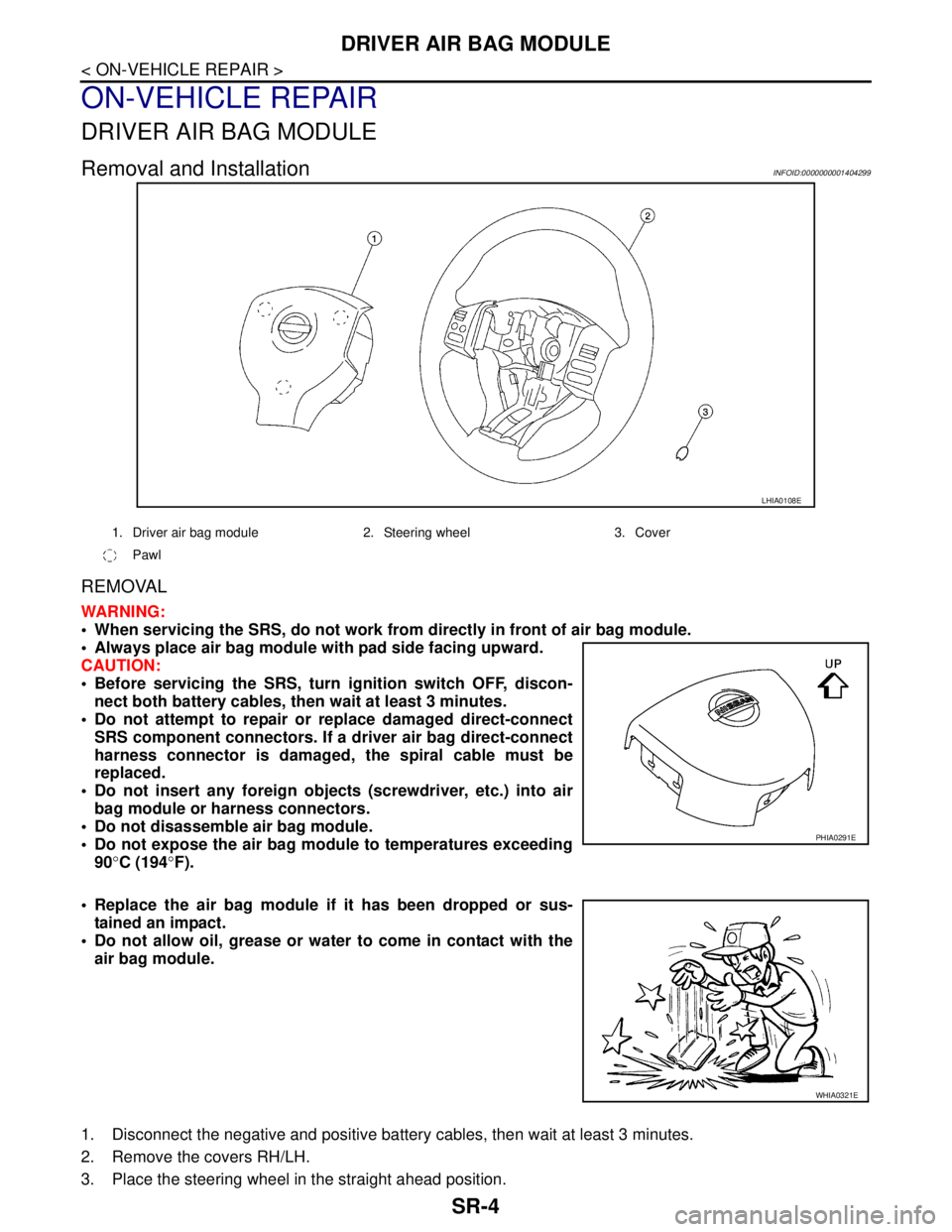
Removal and InstallationINFOID:0000000001404299
REMOVAL
WARNING:
When servicing the SRS, do not work from directly in front of air bag module.
Always place air bag module with pad side facing upward.
CAUTION:
Before servicing the SRS, turn ignition switch OFF, discon-
nect both battery cables, then wait at least 3 minutes.
Do not attempt to repair or replace damaged direct-connect
SRS component connectors. If a driver air bag direct-connect
harness connector is damaged, the spiral cable must be
replaced.
Do not insert any foreign objects (screwdriver, etc.) into air
bag module or harness connectors.
Do not disassemble air bag module.
Do not expose the air bag module to temperatures exceeding
90°C (194°F).
Replace the air bag module if it has been dropped or sus-
tained an impact.
Do not allow oil, grease or water to come in contact with the
air bag module.
1. Disconnect the negative and positive battery cables, then wait at least 3 minutes.
2. Remove the covers RH/LH.
3. Place the steering wheel in the straight ahead position.
LHIA0108E
1. Driver air bag module 2. Steering wheel 3. Cover
Pawl
PHIA0291E
WHIA0321E
Page 4752 of 5883

FRONT PASSENGER AIR BAG MODULE
SR-9
< ON-VEHICLE REPAIR >
C
D
E
F
G
I
J
K
L
MA
B
SR
N
O
P
FRONT PASSENGER AIR BAG MODULE
Removal and InstallationINFOID:0000000001350506
REMOVAL
WARNING:
When servicing the SRS, do not work from directly in front of air bag module.
Always place front passenger air bag module with pad side facing upward.
CAUTION:
Before servicing SRS, turn the ignition switch OFF, disconnect both battery cables and wait at least
3 minutes.
Do not use old bolts after removal; replace with new bolts.
Do not insert any foreign objects (screwdriver, etc.) into air bag module or harness connectors.
Do not disassemble air bag module.
Do not expose the front passenger air bag module to temperatures exceeding 90°C (194°F).
Replace the front passenger air bag module if it has been
dropped or sustained an impact.
Do not allow oil, grease or water to come in contact with the
front passenger air bag module.
1. Disconnect the negative and positive battery cables, then wait at least 3 minutes.
2. Remove the side ventilator assembly (right). Refer to VTL-23, "
Removal and Installation".
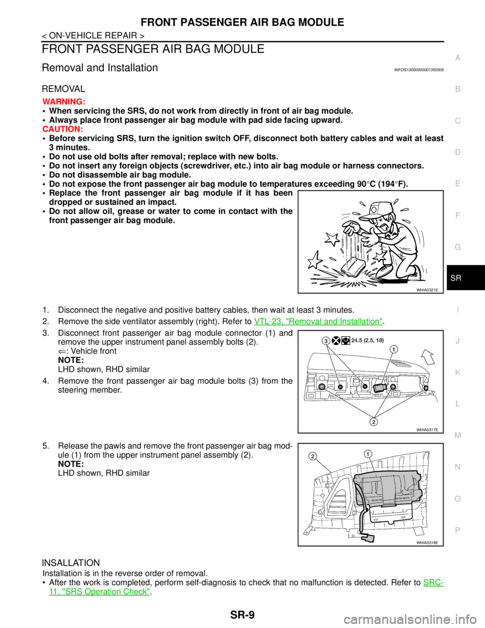
3. Disconnect front passenger air bag module connector (1) and
remove the upper instrument panel assembly bolts (2).
⇐: Vehicle front
NOTE:
LHD shown, RHD similar
4. Remove the front passenger air bag module bolts (3) from the
steering member.
5. Release the pawls and remove the front passenger air bag mod-
ule (1) from the upper instrument panel assembly (2).
NOTE:
LHD shown, RHD similar
INSALLATION
Installation is in the reverse order of removal.
After the work is completed, perform self-diagnosis to check that no malfunction is detected. Refer to SRC-
11 , "SRS Operation Check".
WHIA0321E
WHIA0317E
WHIA0318E
Page 4754 of 5883

SIDE CURTAIN AIR BAG MODULE
SR-11
< ON-VEHICLE REPAIR >
C
D
E
F
G
I
J
K
L
MA
B
SR
N
O
P
When servicing the SRS, do not work from directly in front of air bag module.
Always place the curtain air bag module with deployment side facing upward.
Do not reuse center pillar upper garnish if removed.
CAUTION:
Before servicing SRS, turn the ignition switch OFF, disconnect both battery cables and wait at least
3 minutes.
Do not use old bolts after removal; replace with new bolts.
Do not insert any foreign objects (screwdriver, etc.) into air bag module or harness connectors.
Do not disassemble air bag module.
Do not expose the side curtain air bag module to temperatures exceeding 90°C (194°F).
Replace the side curtain air bag module if it has been dropped
or sustained an impact.
Do not allow oil, grease or water to come in contact with the
side curtain air bag module.
Do not attempt to repair or replace damaged direct-connect
SRS component connectors. If a direct-connect harness con-
nector is damaged, the harness must be replaced.
1. Disconnect both the negative and positive battery cables, then wait at least 3 minutes.
2. Remove the headlining. Refer to INT-29, "
Component".
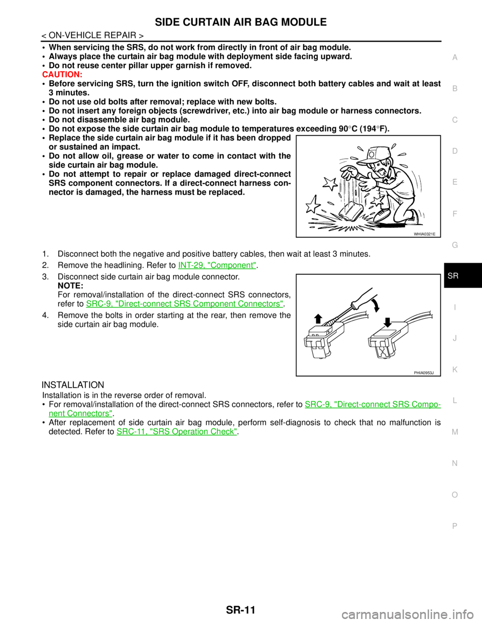
3. Disconnect side curtain air bag module connector.
NOTE:
For removal/installation of the direct-connect SRS connectors,
refer to SRC-9, "
Direct-connect SRS Component Connectors".
4. Remove the bolts in order starting at the rear, then remove the
side curtain air bag module.
INSTALLATION
Installation is in the reverse order of removal.
For removal/installation of the direct-connect SRS connectors, refer to SRC-9, "
Direct-connect SRS Compo-
nent Connectors".
After replacement of side curtain air bag module, perform self-diagnosis to check that no malfunction is
detected. Refer to SRC-11, "
SRS Operation Check".
WHIA0321E
PHIA0953J
Page 4950 of 5883

TM-4
Vehicle Speed When Performing and Releasing
Complete Lock-up .................................................
188
ON-VEHICLE REPAIR ...............................189
TRANSMISSION CONTROL MODULE ..........189
Exploded View .......................................................189
Removal and Installation .......................................189
CONTROL SYSTEM ........................................191
Control Valve Assembly and Accumulators ...........191
PARK/NEUTRAL POSITION (PNP) SWITCH .195
Park/Neutral Position (PNP) Switch ......................195
REVOLUTION SENSOR ..................................197
Revolution Sensor .................................................197
Turbine Revolution Sensor (Power Train Revolu-
tion Sensor) ...........................................................
197
DIFFERENTIAL SIDE OIL SEAL ....................199
Differential Side Oil Seal ........................................199
SHIFT CONTROL SYSTEM ............................200
Control Device Removal and Installation ...............200
Control Device Disassembly and Assembly ..........203
Selector Lever Knob Removal and Installation ......203
Adjustment of A/T Position ....................................204
Checking of A/T Position .......................................204
KEY INTERLOCK CABLE ...............................206
Removal and Installation .......................................206
AIR BREATHER HOSE ...................................209
Removal and Installation .......................................209
REMOVAL AND INSTALLATION ..............210
TRANSAXLE ASSEMBLY ..............................210
Exploded View .......................................................210
Removal and Installation .......................................210
DISASSEMBLY AND ASSEMBLY ............213
OVERHAUL .....................................................213
Component ............................................................213
Oil Channel ............................................................219
Location of Adjusting Shims, Needle Bearings and
Thrust Washers .....................................................
220
Location of Snap Rings .........................................221
DISASSEMBLY ...............................................222
Disassembly ..........................................................222
REPAIR FOR COMPONENT PARTS ..............237
Manual Shaft .........................................................237
Oil Pump ................................................................240
Control Valve Assembly ........................................243
Control Valve Upper Body .....................................252
Control Valve Lower Body .....................................255
Reverse Clutch ......................................................258
High Clutch ............................................................262
Forward and Overrun Clutches .............................267
Low & Reverse Brake ...........................................273
Rear Internal Gear and Forward Clutch Hub ........278
Output Shaft, Output Gear, Idler Gear, Reduction
Pinion Gear and Bearing Retainer ........................
281
Band Servo Piston Assembly ................................287
Final Drive .............................................................292
ASSEMBLY ......................................................297
Assembly (1) .........................................................297
Adjustment (1) .......................................................298
Assembly (2) .........................................................303
Adjustment (2) .......................................................307
Assembly (3) .........................................................311
SERVICE DATA AND SPECIFICATIONS
(SDS) .........................................................
319
SERVICE DATA AND SPECIFICATIONS
(SDS) ................................................................
319
General Specification ............................................319
Vehicle Speed at Which Gear Shifting Occurs .....319
Vehicle Speed at When Lock-up Occurs/Releases
.
319
Stall Speed ............................................................319
Line Pressure ........................................................319
Adjusting shims, Needle Bearings, Thrust Wash-
ers and Snap Rings ..............................................
320
Control Valves .......................................................321
Accumulator ..........................................................321
Clutches and Brakes .............................................321
Final Drive .............................................................323
Planetary Carrier ...................................................323
Oil Pump ...............................................................323
Input Shaft .............................................................323
Reduction Pinion Gear ..........................................323
Band Servo ...........................................................323
Output Shaft ..........................................................323
Bearing Retainer ...................................................324
Total End Play .......................................................324
Reverse Clutch End Play ......................................324
Removal and Installation .......................................324
Shift Solenoid Valves ............................................324
Solenoid Valves ....................................................324
A/T Fluid Temperature Sensor ..............................325
Revolution Sensor .................................................325
Dropping Resistor .................................................325
Turbine Revolution Sensor (Power Train Revolu-
tion Sensor) ...........................................................
325
TYPE 2 (4AT: RE4F03B)
BASIC INSPECTION .................................
326
DIAGNOSIS AND REPAIR WORKFLOW ........326
Work Flow .............................................................326
Diagnostic Work Sheet .........................................327
FUNCTION DIAGNOSIS ...........................329
A/T CONTROL SYSTEM ..................................329
Page 4954 of 5883

TM-8
Band Servo ............................................................616
Output Shaft ..........................................................616
Bearing Retainer ....................................................617
Total End Play .......................................................617
Reverse Clutch End Play .......................................617
Removal and Installation .......................................617
Shift Solenoid Valves .............................................617
Solenoid Valves .....................................................617
A/T Fluid Temperature Sensor ..............................618
Revolution Sensor .................................................618
Dropping Resistor ..................................................618
Turbine Revolution Sensor (Power Train Revolu-
tion Sensor) ...........................................................
618
5MT: RS5F91R
FUNCTION DIAGNOSIS ............................
619
M/T SYSTEM ...................................................619
System Diagram ....................................................619
System Description ................................................620
COMPONENT DIAGNOSIS .......................621
POSITION SWITCH .........................................621
BACK-UP LAMP SWITCH .......................................621
BACK-UP LAMP SWITCH : Component Parts Lo-
cation .....................................................................
621
BACK-UP LAMP SWITCH : Component Inspec-
tion .........................................................................
621
PARK/NEUTRAL POSITION (PNP) SWITCH .........621
PARK/NEUTRAL POSITION (PNP) SWITCH :
Component Parts Location ....................................
621
PARK/NEUTRAL POSITION (PNP) SWITCH :
Component Inspection ...........................................
621
SYMPTOM DIAGNOSIS ............................623
NOISE, VIBRATION AND HARSHNESS
(NVH) TROUBLESHOOTING ..........................
623
NVH Troubleshooting Chart ..................................623
PRECAUTION ............................................624
PRECAUTIONS ...............................................624
Service Notice or Precautions for Manual Tran-
saxle ......................................................................
624
PREPARATION ..........................................625
PREPARATION ...............................................625
Special Service Tools ..........................................625
Commercial Service Tools ...................................627
ON-VEHICLE MAINTENANCE ..................628
GEAR OIL ........................................................628
Exploded View .......................................................628
Draining .................................................................628
Refilling ..................................................................628
Inspection ..............................................................628
ON-VEHICLE REPAIR ..............................629
SIDE OIL SEAL ................................................629
Exploded View ......................................................629
Removal and Installation .......................................629
CONTROL LINKAGE .......................................630
Exploded View ......................................................630
Removal and Installation .......................................630
Inspection ..............................................................631
AIR BREATHER HOSE ....................................632
Exploded View ......................................................632
Removal and Installation .......................................632
REMOVAL AND INSTALLATION .............633
TRANSAXLE ASSEMBLY ...............................633
Exploded View ......................................................633
Removal and Installation .......................................633
DISASSEMBLY AND ASSEMBLY ...........635
TRANSAXLE ASSEMBLY ...............................635
Exploded View ......................................................635
Disassembly ..........................................................639
Assembly ..............................................................645
INPUT SHAFT AND GEAR ..............................653
Exploded View ......................................................653
Disassembly ..........................................................653
Assembly ..............................................................653
Inspection ..............................................................653
MAINSHAFT AND GEAR .................................655
Exploded View ......................................................655
Disassembly ..........................................................655
Assembly ..............................................................656
Inspection ..............................................................657
FINAL DRIVE ....................................................659
Exploded View ......................................................659
Disassembly ..........................................................659
Assembly ..............................................................659
Inspection ..............................................................659
SHIFT CONTROL .............................................661
Exploded View ......................................................661
Disassembly ..........................................................661
Assembly ..............................................................661
Inspection ..............................................................661
SERVICE DATA AND SPECIFICATIONS
(SDS) .........................................................
662
SERVICE DATA AND SPECIFICATIONS
(SDS) ................................................................
662
General Specification ............................................662
6MT: RS6F94R
FUNCTION DIAGNOSIS ...........................
663