2007 NISSAN TIIDA oil temperature
[x] Cancel search: oil temperaturePage 4278 of 5883
MA-38
< ON-VEHICLE MAINTENANCE >
ENGINE MAINTENANCE (MR18DE)
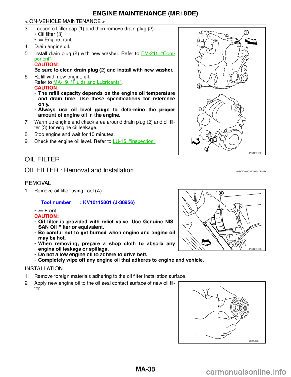
3. Loosen oil filler cap (1) and then remove drain plug (2).
Oil filter (3)
⇐ Engine front
4. Drain engine oil.
5. Install drain plug (2) with new washer. Refer to EM-211, "
Com-
ponent".
CAUTION:
Be sure to clean drain plug (2) and install with new washer.
6. Refill with new engine oil.
Refer to MA-19, "
Fluids and Lubricants".
CAUTION:
The refill capacity depends on the engine oil temperature
and drain time. Use these specifications for reference
only.
Always use oil level gauge to determine the proper
amount of engine oil in the engine.
7. Warm up engine and check area around drain plug (2) and oil fil-
ter (3) for engine oil leakage.
8. Stop engine and wait for 10 minutes.
9. Check the engine oil level. Refer to LU-15, "
Inspection".
OIL FILTER
OIL FILTER : Removal and InstallationINFOID:0000000001730868
REMOVAL
1. Remove oil filter using Tool (A).
⇐ Front
CAUTION:
Oil filter is provided with relief valve. Use Genuine NIS-
SAN Oil Filter or equivalent.
Be careful not to get burned when engine and engine oil
may be hot.
When removing, prepare a shop cloth to absorb any
engine oil leakage or spillage.
Do not allow engine oil to adhere to drive belt.
Completely wipe off any engine oil that adheres to engine and vehicle.
INSTALLATION
1. Remove foreign materials adhering to the oil filter installation surface.
2. Apply new engine oil to the oil seal contact surface of new oil fil-
ter.
PBIC3915E
Tool number : KV10115801 (J-38956)
PBIC3818E
SMA010
Page 4284 of 5883
MA-44
< ON-VEHICLE MAINTENANCE >
ENGINE MAINTENANCE (K9K)
4. Start engine without closing reservoir tank cap and keep engine racing at 1,500 rpm for about 2-3 minutes.
If necessary, pour engine coolant up to MAX level.
If coolant overflows reservoir tank hole, install filler cap.
Watch engine coolant temperature gauge so as not overheat the engine.
WARNING:
Be careful not to be scaled with hot engine coolant or vacuum pump when operating.
Radiator fan blade can start at any time and cause personal injuries.
5. Turn off the engine and loosen air relief plug until coolant spills from air relief hole.
6. Close the air relief plug and run the engine at 2,000 rpm until the upper hose becomes hot and radiator
fan operates. Leave the engine running approximately 5 minutes at idle speed and check for sound of
coolant flow while running engine from idle up to 3,000 rpm.
Sound may be noticeable at heater water cock.
7. If sound is heard, bleed air from cooling system by repeating steps 4 to 6 until coolant level no longer
drops.
Check the radiator lower hose for any signs of leakage.
8. Turn off the engine and let it cool down.
Cool down using a fan to reduce the time.
9. After cooling period, loosen the air relief plug and check if coolant spills from the air relief hole. if not,
remove the air relief plug until the coolant spills, and then close the relief air plug. Bleed air from cooling
system by repeating steps 6 to 10 until the coolant spills immediately.
10. Check the engine coolant level when engine is cool and refill to MAX level line if the level is lower.
Clean excess coolant from engine.
11. Check that the reservoir tank cap is tightened.
ENGINE COOLANT : FlushingINFOID:0000000001730883
1. Install reservoir tank if removed.
If water drain plug on cylinder block is removed, close and tighten it. Refer to EM-314, "
Exploded
View".
2. Fill reservoir tank with water until water spills from the air relief hole, then close air relief plug. Reinstall
reservoir tank cap.
3. Run engine and warm it up to normal operating temperature.
4. Rev engine two or three times under no-load.
5. Stop engine and wait until it cools down.
6. Drain water.
7. Repeat steps 1 through 6 until clear water begins to drain from radiator.
8. Blow compressed air into cooling circuit through the reservoir tank valve hole to drain all the water.
RADIATOR
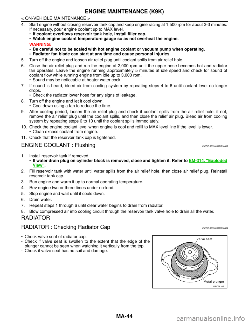
RADIATOR : Checking Radiator CapINFOID:0000000001730884
Check valve seat of radiator cap.
- Check if valve seat is swollen to the extent that the edge of the
plunger cannot be seen when watching it vertically from the top.
- Check if valve seat has no soil and damage.
PBIC2816E
Page 4288 of 5883
MA-48
< ON-VEHICLE MAINTENANCE >
ENGINE MAINTENANCE (K9K)
Prolonged and repeated contact with used engine oil may cause skin cancer: try to avoid direct skin
contact with used oil. If skin contact is made, wash thoroughly with soap or hand cleaner as soon as
possible.
1. Put the vehicle on a level surface.
2. Warm up engine, and check for oil leakage from engine components.
3. Stop engine and wait for 10 minutes.
4. Loosen oil filler cap.
5. Remove drain plug and then drain engine oil.
ENGINE OIL : RefillingINFOID:0000000001730877
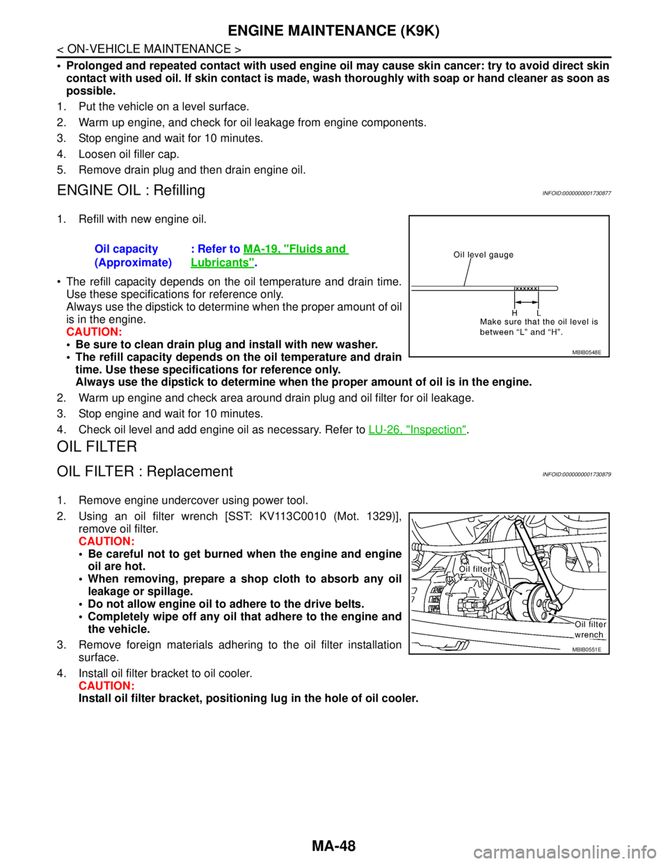
1. Refill with new engine oil.
The refill capacity depends on the oil temperature and drain time.
Use these specifications for reference only.
Always use the dipstick to determine when the proper amount of oil
is in the engine.
CAUTION:
Be sure to clean drain plug and install with new washer.
The refill capacity depends on the oil temperature and drain
time. Use these specifications for reference only.
Always use the dipstick to determine when the proper amount of oil is in the engine.
2. Warm up engine and check area around drain plug and oil filter for oil leakage.
3. Stop engine and wait for 10 minutes.
4. Check oil level and add engine oil as necessary. Refer to LU-26, "
Inspection".
OIL FILTER
OIL FILTER : ReplacementINFOID:0000000001730879
1. Remove engine undercover using power tool.
2. Using an oil filter wrench [SST: KV113C0010 (Mot. 1329)],
remove oil filter.
CAUTION:
Be careful not to get burned when the engine and engine
oil are hot.
When removing, prepare a shop cloth to absorb any oil
leakage or spillage.
Do not allow engine oil to adhere to the drive belts.
Completely wipe off any oil that adhere to the engine and
the vehicle.
3. Remove foreign materials adhering to the oil filter installation
surface.
4. Install oil filter bracket to oil cooler.
CAUTION:
Install oil filter bracket, positioning lug in the hole of oil cooler. Oil capacity
(Approximate): Refer to MA-19, "
Fluids and
Lubricants".
MBIB0548E
MBIB0551E
Page 4309 of 5883

MWI-2
IPDM E/R (INTELLIGENT POWER DISTRIBU-
TION MODULE ENGINE ROOM) : Diagnosis Pro-
cedure .....................................................................
27
FUEL LEVEL SENSOR SIGNAL CIRCUIT .......29
Description ..............................................................29
Component Function Check ...................................29
Diagnosis Procedure .............................................29
Component Inspection ............................................30
OIL PRESSURE SWITCH SIGNAL CIRCUIT ...31
Description ..............................................................31
Component Function Check ...................................31
Diagnosis Procedure ..............................................31
Component Inspection ............................................31
OIL LEVEL SENSOR SIGNAL CIRCUIT ..........32
Description ..............................................................32
Diagnosis Procedure (With Diesel) .........................32
Diagnosis Procedure (Without Diesel) ....................32
Component Inspection (With Diesel) ......................32
Component Inspection (Without Diesel) .................33
AMBIENT SENSOR SIGNAL CIRCUIT .............34
Description ..............................................................34
Diagnosis Procedure ..............................................34
Component Inspection ............................................35
ECU DIAGNOSIS ........................................36
COMBINATION METER ....................................36
Reference Value .....................................................36
Wiring Diagram .......................................................39
Fail Safe .................................................................53
DTC Index ..............................................................54
BCM (BODY CONTROL MODULE) ..................55
Reference Value .....................................................55
Terminal Layout ......................................................58
Physical Values ......................................................58
Wiring Diagram .......................................................70
DTC Inspection Priority Chart ..............................73
DTC Index ..............................................................74
IPDM E/R (INTELLIGENT POWER DISTRI-
BUTION MODULE ENGINE ROOM) .................
75
Reference Value .....................................................75
Terminal Layout ......................................................77
Physical Values ......................................................77
Wiring Diagram .......................................................81
Fail Safe .................................................................84
DTC Index ..............................................................86
SYMPTOM DIAGNOSIS ............................87
THE FUEL GAUGE POINTER DOES NOT
MOVE .................................................................
87
Description ..............................................................87
Diagnosis Procedure ...............................................87
THE FUEL GAUGE POINTER DOES NOT
MOVE TO "F" WHEN REFUELING ..................
88
Description ..............................................................88
Diagnosis Procedure ...............................................88
THE OIL PRESSURE WARNING LAMP
DOES NOT TURN ON .......................................
89
Description ..............................................................89
Diagnosis Procedure ...............................................89
THE OIL PRESSURE WARNING LAMP
DOES NOT TURN OFF .....................................
90
Description ..............................................................90
Diagnosis Procedure ...............................................90
THE AMBIENT TEMPERATURE DISPLAY IS
INCORRECT ......................................................
91
Description ..............................................................91
Diagnosis Procedure ...............................................91
NORMAL OPERATING CONDITION ................92
INFORMATION DISPLAY .........................................92
INFORMATION DISPLAY : Description ..................92
PRECAUTION ............................................93
PRECAUTIONS .................................................93
Supplemental Restraint System (SRS) "AIR BAG"
and "SEAT BELT PRE-TENSIONER" ....................
93
ON-VEHICLE REPAIR ...............................94
COMBINATION METER ....................................94
Removal and Installation .........................................94
DISASSEMBLY AND ASSEMBLY ............97
COMBINATION METER ....................................97
Disassembly and Assembly ....................................97
Page 4314 of 5883
MWI
METER SYSTEM
MWI-7
< FUNCTION DIAGNOSIS >
C
D
E
F
G
H
I
J
K
L
MB A
O
P
METER SYSTEM : Component DescriptionINFOID:0000000001537306
SPEEDOMETER
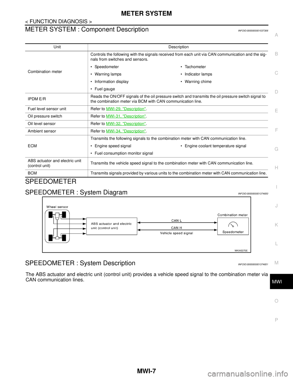
SPEEDOMETER : System DiagramINFOID:0000000001374650
SPEEDOMETER : System DescriptionINFOID:0000000001374651
The ABS actuator and electric unit (control unit) provides a vehicle speed signal to the combination meter via
CAN communication lines.
Unit Description
Combination meterControls the following with the signals received from each unit via CAN communication and the sig-
nals from switches and sensors.
Speedometer Tachometer
Warning lamps Indicator lamps
Information display Warning chime
Fuel gauge
IPDM E/RReads the ON/OFF signals of the oil pressure switch and transmits the oil pressure switch signal to
the combination meter via BCM with CAN communication line.
Fuel level sensor unit Refer to MWI-29, "
Description".
Oil pressure switch Refer to MWI-31, "
Description".
Oil level sensor Refer to MWI-32, "
Description".
Ambient sensor Refer to MWI-34, "
Description".
ECMTransmits the following signals to the combination meter with CAN communication line.
Engine speed signal Engine coolant temperature signal
Fuel consumption monitor signal
ABS actuator and electric unit
(control unit)Transmits the vehicle speed signal to the combination meter with CAN communication line.
BCM Transmits signals provided by various units to the combination meter with CAN communication line.
WKIA5370E
Page 4324 of 5883
MWI
METER SYSTEM
MWI-17
< FUNCTION DIAGNOSIS >
C
D
E
F
G
H
I
J
K
L
MB A
O
P
WARNING LAMPS/INDICATOR LAMPS : Component DescriptionINFOID:0000000001537300
INFORMATION DISPLAY
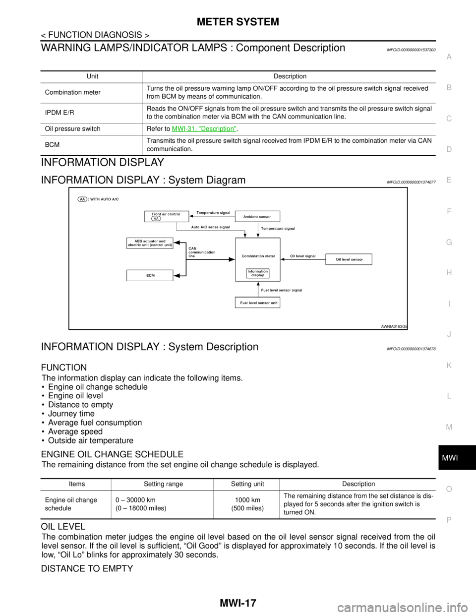
INFORMATION DISPLAY : System DiagramINFOID:0000000001374677
INFORMATION DISPLAY : System DescriptionINFOID:0000000001374678
FUNCTION
The information display can indicate the following items.
Engine oil change schedule
Engine oil level
Distance to empty
Journey time
Average fuel consumption
Average speed
Outside air temperature
ENGINE OIL CHANGE SCHEDULE
The remaining distance from the set engine oil change schedule is displayed.
OIL LEVEL
The combination meter judges the engine oil level based on the oil level sensor signal received from the oil
level sensor. If the oil level is sufficient, “Oil Good” is displayed for approximately 10 seconds. If the oil level is
low, “Oil Lo” blinks for approximately 30 seconds.
DISTANCE TO EMPTY
Unit Description
Combination meterTurns the oil pressure warning lamp ON/OFF according to the oil pressure switch signal received
from BCM by means of communication.
IPDM E/RReads the ON/OFF signals from the oil pressure switch and transmits the oil pressure switch signal
to the combination meter via BCM with the CAN communication line.
Oil pressure switch Refer to MWI-31, "
Description".
BCMTransmits the oil pressure switch signal received from IPDM E/R to the combination meter via CAN
communication.
AWNIA0163GB
Items Setting range Setting unit Description
Engine oil change
schedule0 – 30000 km
(0 – 18000 miles)1000 km
(500 miles)The remaining distance from the set distance is dis-
played for 5 seconds after the ignition switch is
turned ON.
Page 4361 of 5883
MWI-54
< ECU DIAGNOSIS >
COMBINATION METER
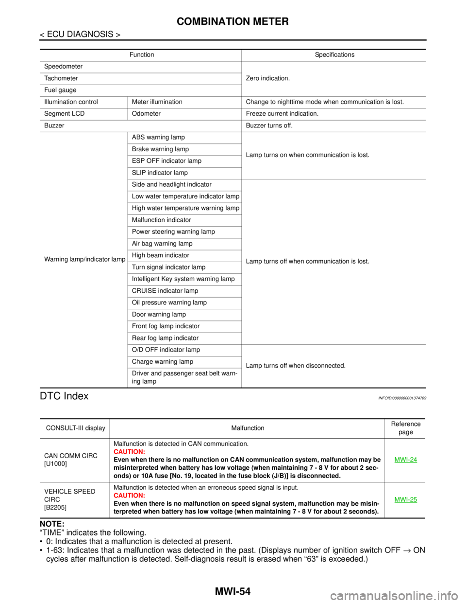
DTC Index
INFOID:0000000001374709
NOTE:
“TIME” indicates the following.
0: Indicates that a malfunction is detected at present.
1-63: Indicates that a malfunction was detected in the past. (Displays number of ignition switch OFF → ON
cycles after malfunction is detected. Self-diagnosis result is erased when “63” is exceeded.)
Function Specifications
Speedometer
Zero indication. Tachometer
Fuel gauge
Illumination control Meter illumination Change to nighttime mode when communication is lost.
Segment LCD Odometer Freeze current indication.
Buzzer Buzzer turns off.
Warning lamp/indicator lampABS warning lamp
Lamp turns on when communication is lost. Brake warning lamp
ESP OFF indicator lamp
SLIP indicator lamp
Side and headlight indicator
Lamp turns off when communication is lost. Low water temperature indicator lamp
High water temperature warning lamp
Malfunction indicator
Power steering warning lamp
Air bag warning lamp
High beam indicator
Turn signal indicator lamp
Intelligent Key system warning lamp
CRUISE indicator lamp
Oil pressure warning lamp
Door warning lamp
Front fog lamp indicator
Rear fog lamp indicator
O/D OFF indicator lamp
Lamp turns off when disconnected. Charge warning lamp
Driver and passenger seat belt warn-
ing lamp
CONSULT-III display MalfunctionReference
page
CAN COMM CIRC
[U1000]Malfunction is detected in CAN communication.
CAUTION:
Even when there is no malfunction on CAN communication system, malfunction may be
misinterpreted when battery has low voltage (when maintaining 7 - 8 V for about 2 sec-
onds) or 10A fuse [No. 19, located in the fuse block (J/B)] is disconnected.MWI-24
VEHICLE SPEED
CIRC
[B2205]Malfunction is detected when an erroneous speed signal is input.
CAUTION:
Even when there is no malfunction on speed signal system, malfunction may be misin-
terpreted when battery has low voltage (when maintaining 7 - 8 V for about 2 seconds). MWI-25
Page 4364 of 5883
MWI
BCM (BODY CONTROL MODULE)
MWI-57
< ECU DIAGNOSIS >
C
D
E
F
G
H
I
J
K
L
MB A
O
P
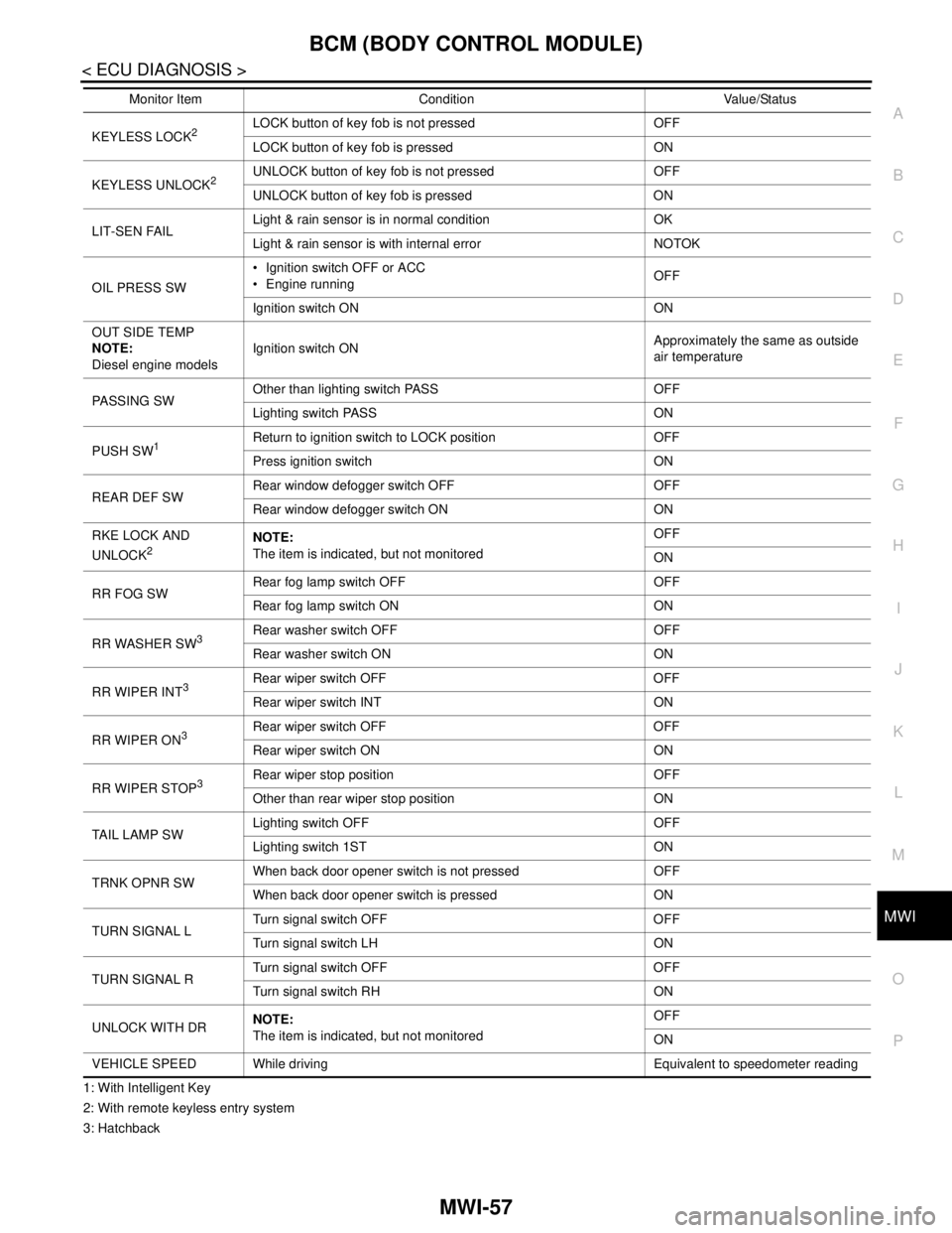
1: With Intelligent Key
2: With remote keyless entry system
3: HatchbackKEYLESS LOCK
2LOCK button of key fob is not pressed OFF
LOCK button of key fob is pressed ON
KEYLESS UNLOCK
2UNLOCK button of key fob is not pressed OFF
UNLOCK button of key fob is pressed ON
LIT-SEN FAILLight & rain sensor is in normal condition OK
Light & rain sensor is with internal error NOTOK
OIL PRESS SW Ignition switch OFF or ACC
Engine runningOFF
Ignition switch ON ON
OUT SIDE TEMP
NOTE:
Diesel engine modelsIgnition switch ONApproximately the same as outside
air temperature
PASSING SWOther than lighting switch PASS OFF
Lighting switch PASS ON
PUSH SW
1Return to ignition switch to LOCK position OFF
Press ignition switch ON
REAR DEF SWRear window defogger switch OFF OFF
Rear window defogger switch ON ON
RKE LOCK AND
UNLOCK
2NOTE:
The item is indicated, but not monitoredOFF
ON
RR FOG SWRear fog lamp switch OFF OFF
Rear fog lamp switch ON ON
RR WASHER SW
3Rear washer switch OFF OFF
Rear washer switch ON ON
RR WIPER INT
3Rear wiper switch OFF OFF
Rear wiper switch INT ON
RR WIPER ON
3 Rear wiper switch OFF OFF
Rear wiper switch ON ON
RR WIPER STOP
3Rear wiper stop position OFF
Other than rear wiper stop position ON
TAIL LAMP SWLighting switch OFF OFF
Lighting switch 1ST ON
TRNK OPNR SWWhen back door opener switch is not pressed OFF
When back door opener switch is pressed ON
TURN SIGNAL LTurn signal switch OFF OFF
Turn signal switch LH ON
TURN SIGNAL RTurn signal switch OFF OFF
Turn signal switch RH ON
UNLOCK WITH DRNOTE:
The item is indicated, but not monitoredOFF
ON
VEHICLE SPEED While driving Equivalent to speedometer reading Monitor Item Condition Value/Status