Page 3082 of 5883
HEADLAMP
EXL-81
< ON-VEHICLE MAINTENANCE >
C
D
E
F
G
H
I
J
K
MA
B
EXL
N
O
P
ON-VEHICLE MAINTENANCE
HEADLAMP
Aiming AdjustmentINFOID:0000000001529251
PREPARATION BEFORE ADJUSTING
Before performing aiming adjustment, check the following.
1. Keep all tires inflated to correct pressures.
2. Place vehicle on level surface.
3. Set that there is no-load in vehicle other than the driver (or equivalent weight placed in driver's position).
Coolant, engine oil filled up to correct level and full fuel tank.
LOW BEAM AND HIGH BEAM
1. Turn headlamp low beam ON.
2. Use adjusting screw to perform aiming adjustment.
ADJUSTMENT USING AN ADJUSTMENT SCREEN (LIGHT/DARK BORDERLINE)
1. Headlamp A. Inner and outer adjustment B. Adjusting screw
WKIA5417E
Page 3083 of 5883

EXL-82
< ON-VEHICLE MAINTENANCE >
HEADLAMP
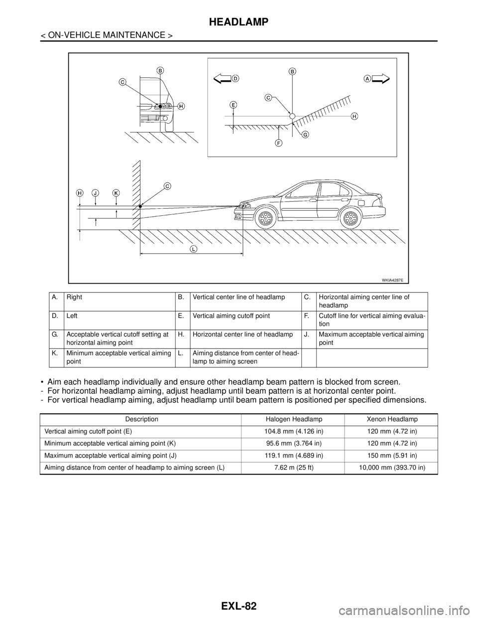
Aim each headlamp individually and ensure other headlamp beam pattern is blocked from screen.
- For horizontal headlamp aiming, adjust headlamp until beam pattern is at horizontal center point.
- For vertical headlamp aiming, adjust headlamp until beam pattern is positioned per specified dimensions.
A. Right B. Vertical center line of headlamp C. Horizontal aiming center line of
headlamp
D. Left E. Vertical aiming cutoff point F. Cutoff line for vertical aiming evalua-
tion
G. Acceptable vertical cutoff setting at
horizontal aiming pointH. Horizontal center line of headlamp J. Maximum acceptable vertical aiming
point
K. Minimum acceptable vertical aiming
pointL. Aiming distance from center of head-
lamp to aiming screen
WKIA4287E
Description Halogen Headlamp Xenon Headlamp
Vertical aiming cutoff point (E) 104.8 mm (4.126 in) 120 mm (4.72 in)
Minimum acceptable vertical aiming point (K) 95.6 mm (3.764 in) 120 mm (4.72 in)
Maximum acceptable vertical aiming point (J) 119.1 mm (4.689 in) 150 mm (5.91 in)
Aiming distance from center of headlamp to aiming screen (L) 7.62 m (25 ft) 10,000 mm (393.70 in)
Page 3084 of 5883

FRONT FOG LAMP
EXL-83
< ON-VEHICLE MAINTENANCE >
C
D
E
F
G
H
I
J
K
MA
B
EXL
N
O
P
FRONT FOG LAMP
Aiming AdjustmentINFOID:0000000001529283
The front fog lamp is a semi-sealed beam type which uses a replaceable halogen bulb. Before performing
aiming adjustment, make sure of the following.
Keep all tires inflated to correct pressure.
Place vehicle on level surface.
Set that there is no-load in vehicle other than the driver (or equivalent weight placed in driver’s position).
Coolant, engine oil filled up to correct level and full fuel tank.
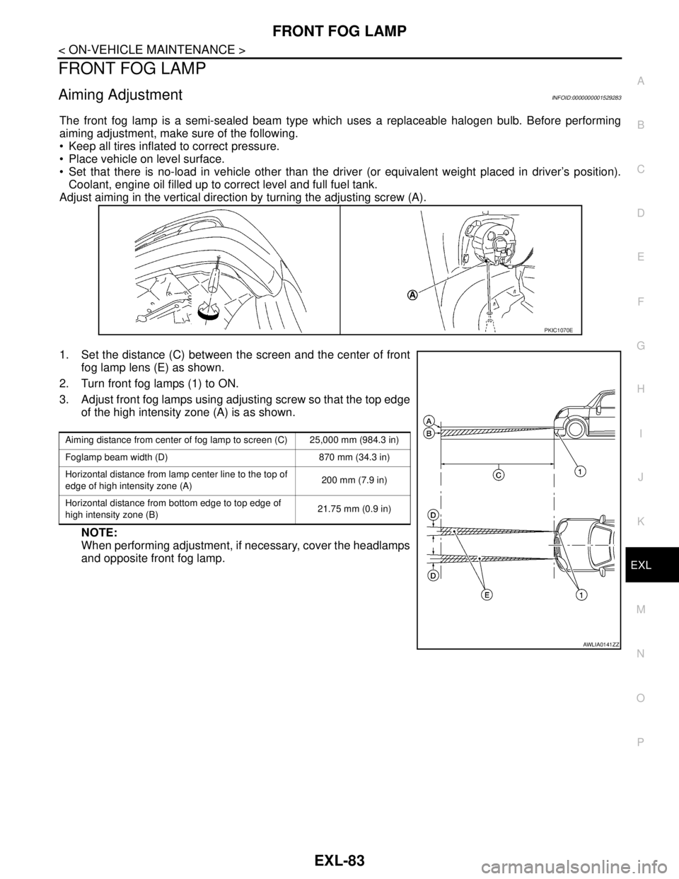
Adjust aiming in the vertical direction by turning the adjusting screw (A).
1. Set the distance (C) between the screen and the center of front
fog lamp lens (E) as shown.
2. Turn front fog lamps (1) to ON.
3. Adjust front fog lamps using adjusting screw so that the top edge
of the high intensity zone (A) is as shown.
NOTE:
When performing adjustment, if necessary, cover the headlamps
and opposite front fog lamp.
PKIC1070E
Aiming distance from center of fog lamp to screen (C) 25,000 mm (984.3 in)
Foglamp beam width (D) 870 mm (34.3 in)
Horizontal distance from lamp center line to the top of
edge of high intensity zone (A)200 mm (7.9 in)
Horizontal distance from bottom edge to top edge of
high intensity zone (B)21.75 mm (0.9 in)
AWLIA0141ZZ
Page 3273 of 5883
GW-14
< ON-VEHICLE REPAIR >
FRONT DOOR GLASS AND REGULATOR
FRONT DOOR GLASS AND REGULATOR
Removal and InstallationINFOID:0000000001716843
DOOR GLASS
Removal
1. Remove the front door finisher. Refer to INT-13, "Removal and Installation".
2. Disconnect the front door speaker electrical connector.
3. Position aside the sealing screen.
NOTE:
If sealing the screen is reused, cut the butyl-tape so that a part of butyl-tape remains on the sealing
screen.
4. If equipped, reconnect the power window switch electrical con-
nector. Operate the power window main switch to raise/lower
the door window until the glass bolts can be seen.
5. Remove the door glass bolts.
1. Door panel 2. Lower sash (front) 3. Lower sash (rear)
4. Door glass run 5. Door glass 6. Regulator assembly
7. Power window motor (if equipped)
PIIB2631J
PIIB2632J
Page 3274 of 5883

FRONT DOOR GLASS AND REGULATOR
GW-15
< ON-VEHICLE REPAIR >
C
D
E
F
G
H
I
J
L
MA
B
GW
N
O
P
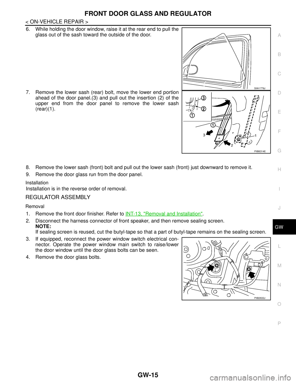
6. While holding the door window, raise it at the rear end to pull the
glass out of the sash toward the outside of the door.
7. Remove the lower sash (rear) bolt, move the lower end portion
ahead of the door panel.(3) and pull out the insertion (2) of the
upper end from the door panel to remove the lower sash
(rear)(1).
8. Remove the lower sash (front) bolt and pull out the lower sash (front) just downward to remove it.
9. Remove the door glass run from the door panel.
Installation
Installation is in the reverse order of removal.
REGULATOR ASSEMBLY
Removal
1. Remove the front door finisher. Refer to INT-13, "Removal and Installation".
2. Disconnect the harness connector of front speaker, and then remove sealing screen.
NOTE:
If sealing screen is reused, cut the butyl-tape so that a part of butyl-tape remains on the sealing screen.
3. If equipped, reconnect the power window switch electrical con-
nector. Operate the power window main switch to raise/lower
the door window until the door glass bolts can be seen.
4. Remove the door glass bolts.
SIIA1779J
PIIB6314E
PIIB2632J
Page 3280 of 5883
REAR DOOR GLASS AND REGULATOR
GW-21
< ON-VEHICLE REPAIR >
C
D
E
F
G
H
I
J
L
MA
B
GW
N
O
P
REAR DOOR GLASS AND REGULATOR
Removal and InstallationINFOID:0000000001716846
DOOR GLASS
Removal
1. Remove position aside the rear door finisher. Refer to INT-13, "Removal and Installation".
2. Disconnect the harness connector of rear door speaker.
3. Position aside the sealing screen.
NOTE:
If the sealing screen is reused, cut the butyl-tape so that a part of the butyl-tape remains on the sealing
screen.
4. Remove partition sash bolt and screw, pull the partition sash
downward and tilt the upper end of the sash forward to pull out
the sash upward.
1. Door panel 2. Partition sash 3. Door glass run
4. Partition glass weatherstrip 5. Door glass 6. Partition glass
7. Regulator assembly 8. Power window motor (if equipped)
PIIB2634J
PIIB2635J
Page 3281 of 5883

GW-22
< ON-VEHICLE REPAIR >
REAR DOOR GLASS AND REGULATOR
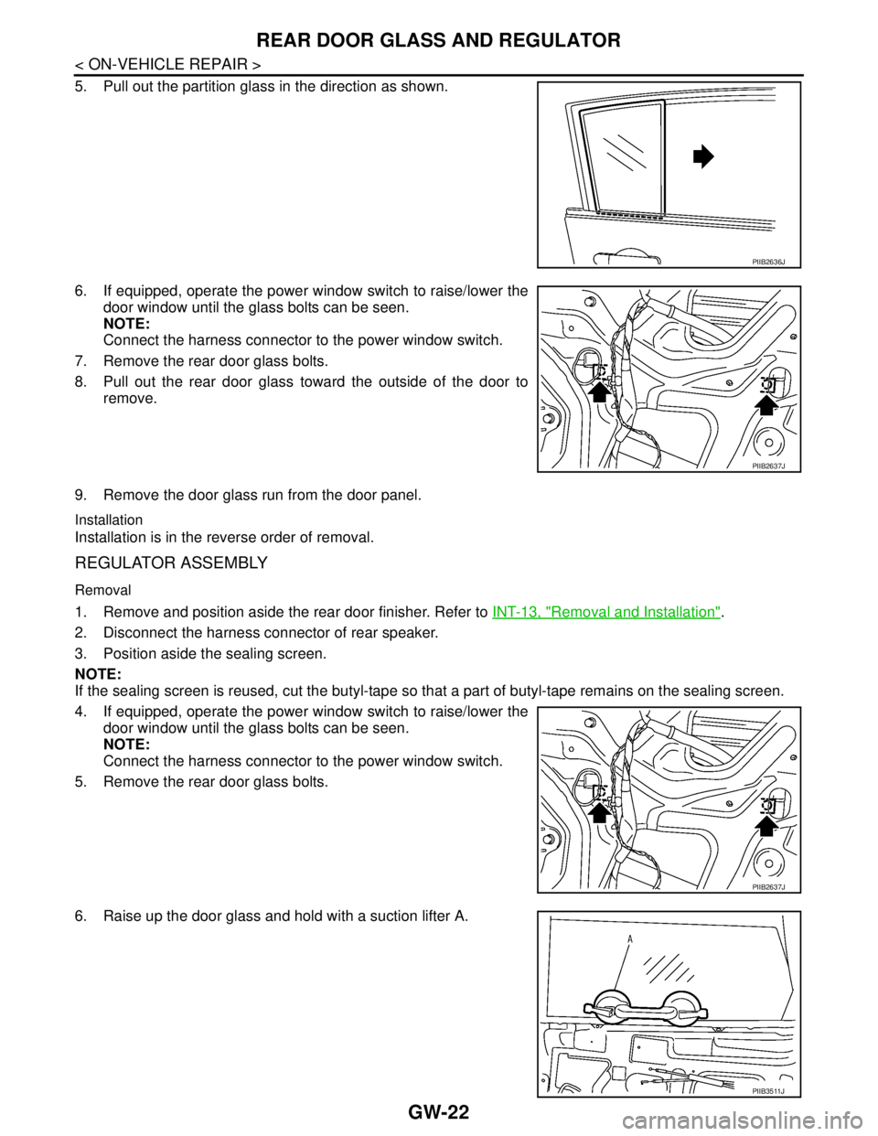
5. Pull out the partition glass in the direction as shown.
6. If equipped, operate the power window switch to raise/lower the
door window until the glass bolts can be seen.
NOTE:
Connect the harness connector to the power window switch.
7. Remove the rear door glass bolts.
8. Pull out the rear door glass toward the outside of the door to
remove.
9. Remove the door glass run from the door panel.
Installation
Installation is in the reverse order of removal.
REGULATOR ASSEMBLY
Removal
1. Remove and position aside the rear door finisher. Refer to INT-13, "Removal and Installation".
2. Disconnect the harness connector of rear speaker.
3. Position aside the sealing screen.
NOTE:
If the sealing screen is reused, cut the butyl-tape so that a part of butyl-tape remains on the sealing screen.
4. If equipped, operate the power window switch to raise/lower the
door window until the glass bolts can be seen.
NOTE:
Connect the harness connector to the power window switch.
5. Remove the rear door glass bolts.
6. Raise up the door glass and hold with a suction lifter A.
PIIB2636J
PIIB2637J
PIIB2637J
PIIB3511J
Page 3432 of 5883
![NISSAN TIIDA 2007 Service Repair Manual SELF-DIAGNOSIS FUNCTION
HAC-99
< FUNCTION DIAGNOSIS >[AUTO AIR CONDITIONER (W/O NAVI)]
C
D
E
F
G
H
J
K
L
MA
B
HAC
N
O
P
CAUTION:
If battery voltage drops below 12V during diagnosis STEP-3, door motor NISSAN TIIDA 2007 Service Repair Manual SELF-DIAGNOSIS FUNCTION
HAC-99
< FUNCTION DIAGNOSIS >[AUTO AIR CONDITIONER (W/O NAVI)]
C
D
E
F
G
H
J
K
L
MA
B
HAC
N
O
P
CAUTION:
If battery voltage drops below 12V during diagnosis STEP-3, door motor](/manual-img/5/57395/w960_57395-3431.png)
SELF-DIAGNOSIS FUNCTION
HAC-99
< FUNCTION DIAGNOSIS >[AUTO AIR CONDITIONER (W/O NAVI)]
C
D
E
F
G
H
J
K
L
MA
B
HAC
N
O
P
CAUTION:
If battery voltage drops below 12V during diagnosis STEP-3, door motor speed becomes slower and
as a result, the system may generate an error even when operation is usual. To avoid this, start engine
before performing this diagnosis.
>> GO TO 2.
2.STEP-1: LED AND DISPLAY ARE CHECKED
Check display screen (1) and LED illumination (2).
OK or NG
OK >> GO TO 3.
NG >> Malfunction OFF switch or AUTO switch. Refer to HAC-
311, "Self-Diagnosis".
3.CHECK TO ADVANCE SELF-DIAGNOSIS STEP-2
Press temperature control switch (UP: ).
Advance to self
-diagnosis STEP-2?
YES >> GO TO 4.
NO >> Replace front air control (temperature control switch is malfunctioning). Refer to XX.
4.CHECK TO RETURN SELF-DIAGNOSIS STEP-1
Press temperature control switch (DOWN: ).
Return to self
-diagnosis STEP-1?
YES >> GO TO 5.
NO >> Replace front air control (temperature control switch is malfunctioning). Refer to XX.
5.STEP-2: SENSOR CIRCUITS ARE CHECKED FOR OPEN OR SHORT CIRCUIT
Press temperature control switch (UP: ).
Does code No. 20 appear on the display?
YES >> GO TO 6.
NO >> GO TO 13.
6.STEP-3: AIR MIX DOOR AND MODE DOOR POSITIONS ARE CHECKED
Press temperature control switch (UP: ).
Does code No. 30 appear on the display?
YES >> GO TO 7.
NO >> GO TO 14.
AWIIA0285ZZ
SJIA0737E
SJIA0738E