Page 3680 of 5883

INT-1
BODY INTERIOR
C
D
E
F
G
H
I
K
L
M
SECTION INT
A
B
INT
N
O
P
CONTENTS
INTERIOR
PRECAUTION ...............................................2
PRECAUTIONS ...................................................2
Precaution for Supplemental Restraint System
(SRS) "AIR BAG" and "SEAT BELT PRE-TEN-
SIONER" ...................................................................
2
Precaution .................................................................2
PREPARATION ............................................3
PREPARATION ...................................................3
Commercial Service Tool ..........................................3
CLIP AND FASTENER ........................................4
Description ................................................................4
SQUEAK AND RATTLE TROUBLE DIAGNO-
SIS .......................................................................
7
Work Flow .................................................................7
Generic Squeak and Rattle Troubleshooting ............9
Diagnostic Worksheet .............................................11
ON-VEHICLE REPAIR .................................13
DOOR FINISHER ...............................................13
Removal and Installation .........................................13
TRUNK LID FINISHER ......................................17
Removal and Installation .........................................17
BACK DOOR TRIM ...........................................18
Removal and Installation .........................................18
BODY SIDE TRIM .............................................19
Component ..............................................................19
Removal and Installation .........................................20
LUGGAGE FLOOR TRIM .................................24
Removal and Installation .........................................24
REAR PARCEL SHELF FINISHER ..................26
Removal and Installation .........................................26
FLOOR TRIM ....................................................27
Removal and Installation .........................................27
HEADLINING ....................................................29
Component ..............................................................29
Removal and Installation - Hatchback .....................31
Removal and Installation - Sedan ............................33
TRUNK ROOM TRIM & TRUNK LID FINISH-
ER ......................................................................
35
Removal and Installation .........................................35
Page 3698 of 5883
BODY SIDE TRIM
INT-19
< ON-VEHICLE REPAIR >
C
D
E
F
G
H
I
K
L
MA
B
INT
N
O
P
BODY SIDE TRIM
ComponentINFOID:0000000001329051
Hatchback Models
AWJIA0060ZZ
1. Front pillar garnish 2. Front body side welt 3. Front kicking plate inner
4. Front kicking plate outer 5. Center pillar lower garnish 6. Rear kicking plate inner
7. Rear pillar finisher 8. Rear body side welt 9. Rear kicking plate outer
10. Center pillar upper garnish Pawl Metal clip
Clip⇐Vehicle front
Page 3708 of 5883
HEADLINING
INT-29
< ON-VEHICLE REPAIR >
C
D
E
F
G
H
I
K
L
MA
B
INT
N
O
P
HEADLINING
ComponentINFOID:0000000001329055
LHD Hatchback Models Shown, RHD Similar
LIIA2576E
1. Headlining 2. Assist grip 3. Sunvisor
4. Cap 5. Sunvisor holder 6. Roof console retainer
Page 3710 of 5883

HEADLINING
INT-31
< ON-VEHICLE REPAIR >
C
D
E
F
G
H
I
K
L
MA
B
INT
N
O
P
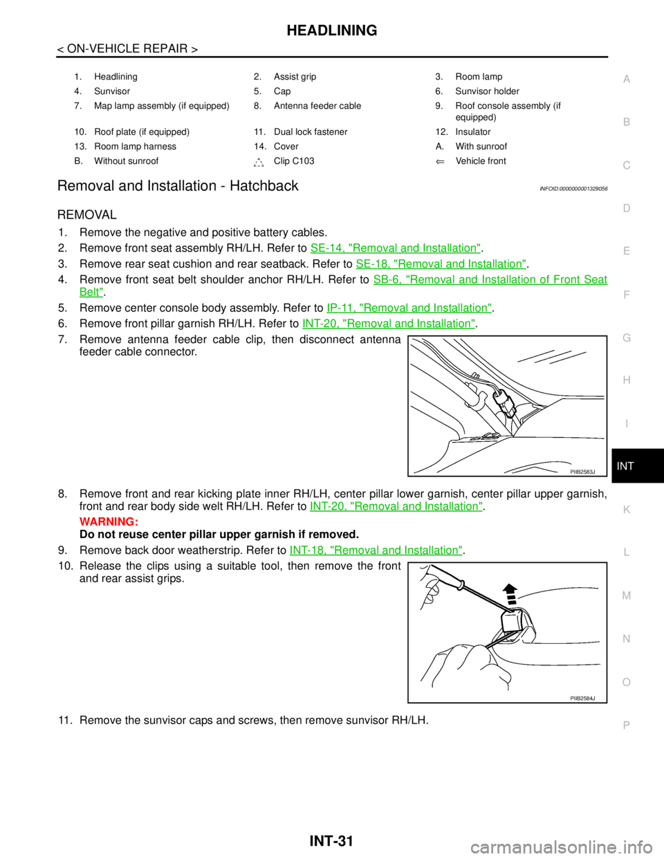
Removal and Installation - HatchbackINFOID:0000000001329056
REMOVAL
1. Remove the negative and positive battery cables.
2. Remove front seat assembly RH/LH. Refer to SE-14, "
Removal and Installation".
3. Remove rear seat cushion and rear seatback. Refer to SE-18, "
Removal and Installation".
4. Remove front seat belt shoulder anchor RH/LH. Refer to SB-6, "
Removal and Installation of Front Seat
Belt".
5. Remove center console body assembly. Refer to IP-11, "
Removal and Installation".
6. Remove front pillar garnish RH/LH. Refer to INT-20, "
Removal and Installation".
7. Remove antenna feeder cable clip, then disconnect antenna
feeder cable connector.
8. Remove front and rear kicking plate inner RH/LH, center pillar lower garnish, center pillar upper garnish,
front and rear body side welt RH/LH. Refer to INT-20, "
Removal and Installation".
WARNING:
Do not reuse center pillar upper garnish if removed.
9. Remove back door weatherstrip. Refer to INT-18, "
Removal and Installation".
10. Release the clips using a suitable tool, then remove the front
and rear assist grips.
11. Remove the sunvisor caps and screws, then remove sunvisor RH/LH.
1. Headlining 2. Assist grip 3. Room lamp
4. Sunvisor 5. Cap 6. Sunvisor holder
7. Map lamp assembly (if equipped) 8. Antenna feeder cable 9. Roof console assembly (if
equipped)
10. Roof plate (if equipped) 11. Dual lock fastener 12. Insulator
13. Room lamp harness 14. Cover A. With sunroof
B. Without sunroof Clip C103⇐Vehicle front
PIIB2583J
PIIB2584J
Page 3770 of 5883
LAN-30
< FUNCTION DIAGNOSIS >[CAN]
CAN COMMUNICATION SYSTEM
FUNCTION DIAGNOSIS
CAN COMMUNICATION SYSTEM
CAN System Specification ChartINFOID:0000000001162800
NOTE:
Refer to LAN-22, "
Trouble Diagnosis Procedure" for how to use CAN system specification chart.
Refer to the specification as shown in the chart.
SPECIFICATION CHART A
Determine CAN system type from the following specification chart.
×: Applicable
VEHICLE EQUIPMENT IDENTIFICATION INFORMATION
NOTE:
Body type Hatchback/Sedan
Axle 2WD
Engine K9K HR16DE MR18DE
Transmission M/T A/T M/T
Brake control ABS/ESP
Specification chart SPECIFICATION CHART
ASPECIFICATION CHART BSPECIFICATION CHART
C
Body type Hatchback/Sedan
Axle 2WD
Engine K9K
Transmission M/T
Brake control ABS ESP
Intelligent Key system×× ××
Navigation system××××
CAN system type 12345678
Start CAN Diagnosis
(CONSULT-III)12345678
Page 3771 of 5883
LAN
CAN COMMUNICATION SYSTEM
LAN-31
< FUNCTION DIAGNOSIS >[CAN]
C
D
E
F
G
H
I
J
K
L B A
O
P N
Check CAN system type from the vehicle shape and equipment.
SPECIFICATION CHART B
Determine CAN system type from the following specification chart.
×: Applicable
VEHICLE EQUIPMENT IDENTIFICATION INFORMATION
NOTE:
ALMIA0068GB
Body type Hatchback/Sedan
Axle 2WD
Engine HR16DE
Transmission M/T A/T
Brake control ABS ESP ABS ESP
Intelligent Key system×× ×× ×× ××
Navigation system××××××××
CAN system type 9 101112131415161718192021222324
Start CAN Diagnosis
(CONSULT-III)9 101112131415161718192021222324
Page 3772 of 5883
LAN-32
< FUNCTION DIAGNOSIS >[CAN]
CAN COMMUNICATION SYSTEM
Check CAN system type from the vehicle shape and equipment.
SPECIFICATION CHART C
Determine CAN system type from the following specification chart.
×: Applicable
VEHICLE EQUIPMENT IDENTIFICATION INFORMATION
NOTE:
ALMIA0068GB
Body type Hatchback/Sedan
Axle 2WD
Engine MR18DE
Transmission M/T
Brake control ABS ESP
Intelligent Key system×× ××
Navigation system××××
CAN system type 25 26 27 28 29 30 31 32
Start CAN Diagnosis
(CONSULT-III)25 26 27 28 29 30 31 32
Page 4364 of 5883

MWI
BCM (BODY CONTROL MODULE)
MWI-57
< ECU DIAGNOSIS >
C
D
E
F
G
H
I
J
K
L
MB A
O
P
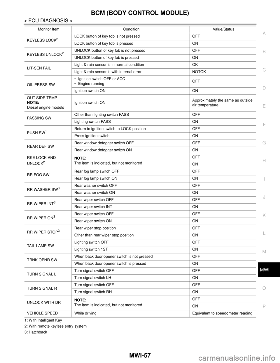
1: With Intelligent Key
2: With remote keyless entry system
3: HatchbackKEYLESS LOCK
2LOCK button of key fob is not pressed OFF
LOCK button of key fob is pressed ON
KEYLESS UNLOCK
2UNLOCK button of key fob is not pressed OFF
UNLOCK button of key fob is pressed ON
LIT-SEN FAILLight & rain sensor is in normal condition OK
Light & rain sensor is with internal error NOTOK
OIL PRESS SW Ignition switch OFF or ACC
Engine runningOFF
Ignition switch ON ON
OUT SIDE TEMP
NOTE:
Diesel engine modelsIgnition switch ONApproximately the same as outside
air temperature
PASSING SWOther than lighting switch PASS OFF
Lighting switch PASS ON
PUSH SW
1Return to ignition switch to LOCK position OFF
Press ignition switch ON
REAR DEF SWRear window defogger switch OFF OFF
Rear window defogger switch ON ON
RKE LOCK AND
UNLOCK
2NOTE:
The item is indicated, but not monitoredOFF
ON
RR FOG SWRear fog lamp switch OFF OFF
Rear fog lamp switch ON ON
RR WASHER SW
3Rear washer switch OFF OFF
Rear washer switch ON ON
RR WIPER INT
3Rear wiper switch OFF OFF
Rear wiper switch INT ON
RR WIPER ON
3 Rear wiper switch OFF OFF
Rear wiper switch ON ON
RR WIPER STOP
3Rear wiper stop position OFF
Other than rear wiper stop position ON
TAIL LAMP SWLighting switch OFF OFF
Lighting switch 1ST ON
TRNK OPNR SWWhen back door opener switch is not pressed OFF
When back door opener switch is pressed ON
TURN SIGNAL LTurn signal switch OFF OFF
Turn signal switch LH ON
TURN SIGNAL RTurn signal switch OFF OFF
Turn signal switch RH ON
UNLOCK WITH DRNOTE:
The item is indicated, but not monitoredOFF
ON
VEHICLE SPEED While driving Equivalent to speedometer reading Monitor Item Condition Value/Status