Page 3233 of 5883
IDENTIFICATION INFORMATION
GI-39
< FEATURES OF NEW MODEL >
C
D
E
F
G
H
I
J
K
L
MB
GI
N
O
P
IDENTIFICATION NUMBER
VEHICLE IDENTIFICATION NUMBER ARRANGEMENT
6BGradeB: Visia
E: Acenta
T: Te k n a
7 Y TransmissionY: 6 M/ T
F: 5 M/T
A: 4 A/T
8
C11 Model code C11: Tiida 9
10
11 E Intake E: EGI
12 E ZoneE: Europe A (RHD)
G: Europe B (LHD)
Q: Russia
13 A Equipment A: Standard
14
xxxxx Option Codes 15
16
17 Position (Left to
Right)Character Qualifier Definition
1. Chassis number 2. Emissions control label 3. VIN number
4. FMVSS/CMVSS certification and tire
placard labels
LAIA0073E
VIN Position (Left
to Right)Character Qualifier Definition
1
3N1World Manufacturer Identifi-
cation3N1: Mexico 2
3
4 B Body typeB: 4-door sedan
F: 4-door hatchback
Page 3235 of 5883
IDENTIFICATION INFORMATION
GI-41
< FEATURES OF NEW MODEL >
C
D
E
F
G
H
I
J
K
L
MB
GI
N
O
P
HR1.6 L
K9K (1.5 DCI)
AUTOMATIC TRANSAXLE NUMBER
MANUAL TRANSAXLE NUMBER
DimensionsINFOID:0000000001606152
Unit: mm (in)
ALAIA0002ZZ
ALAIA0003ZZ
SGI113A
PCIB1612E
Overall length Hatchback: 4,295 (169.1) Sedan: 4470 (176)
Overall width1,694.2 (66.7)
Overall height1,534.1 (60.4)
Front tread1,480 (58.3)
Page 3269 of 5883
GW-10
< ON-VEHICLE REPAIR >
WINDSHIELD GLASS
ON-VEHICLE REPAIR
WINDSHIELD GLASS
Removal and InstallationINFOID:0000000001716818
REMOVAL
1. Partially remove the headlining (front edge). Refer to INT-31, "Removal and Installation - Hatchback" INT-
33, "Removal and Installation - Sedan".
2. Remove the front wiper arms. Refer to WW-70, "
Removal and Installation".
3. Remove the cowl top cover. Refer to EXT-20, "
Removal and Installation".
4. Disconnect the harness connector of wiper deicer.
5. Apply protective tape around the windshield glass to protect the painted surface from damage.
PIIB6285E
1. Windshield glass assembly 2. Dam sealant 3. Windshield molding
4. Spacer 5. Mirror base 6. Roof panel outer
7. Cowl top front 8. Adhesive 9. Front pillar outer panel
10. Cowl top cover 11. Primer
Page 3277 of 5883
GW-18
< ON-VEHICLE REPAIR >
REAR WINDOW GLASS AND MOLDING
REAR WINDOW GLASS AND MOLDING
Removal and InstallationINFOID:0000000001716820
Hatchback
LIIA2924E
1. Dam rubber 2. Back door window molding (Lower) 3. Back door window glass
4. Clip (Upper) 5. Clip (Lower) 6. Adhesive
7. Back door outer panel 8. Primer
Page 3657 of 5883

INL-6
< FUNCTION DIAGNOSIS >
INTERIOR ROOM LAMP CONTROL SYSTEM
a signal is received from an Intelligent Key or main power window and door lock/unlock switch, or when the
front door LH lock assembly (key cylinder switch) is locked or unlocked
a door is opened or closed
the Intelligent Key is removed from or inserted into the key slot.
The Interior lamp battery saver control time period can be changed with the function setting of CONSULT-III.
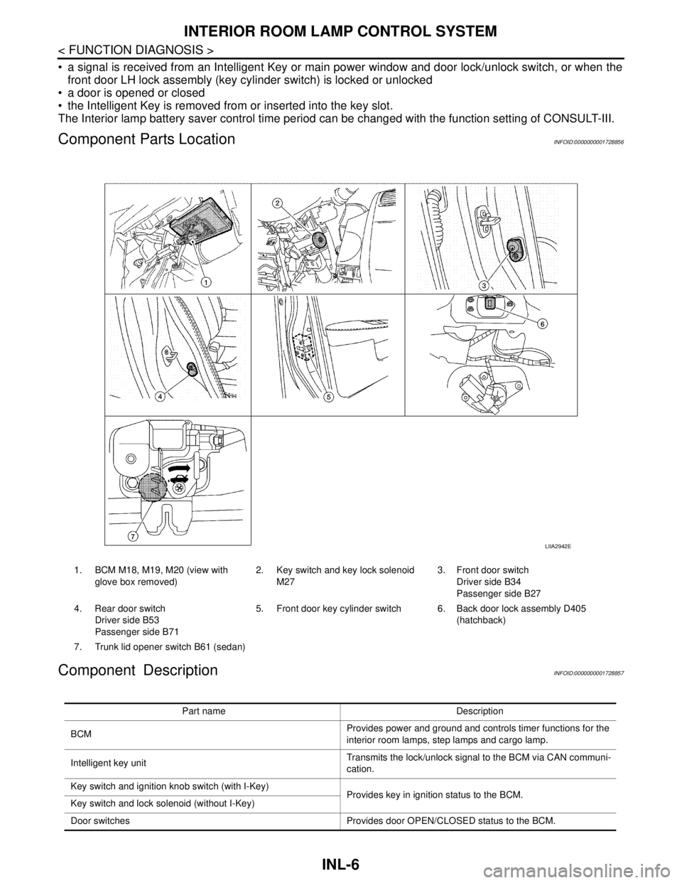
Component Parts LocationINFOID:0000000001728856
Component DescriptionINFOID:0000000001728857
1. BCM M18, M19, M20 (view with
glove box removed)2. Key switch and key lock solenoid
M273. Front door switch
Driver side B34
Passenger side B27
4. Rear door switch
Driver side B53
Passenger side B715. Front door key cylinder switch 6. Back door lock assembly D405
(hatchback)
7. Trunk lid opener switch B61 (sedan)
LIIA2942E
Part name Description
BCMProvides power and ground and controls timer functions for the
interior room lamps, step lamps and cargo lamp.
Intelligent key unitTransmits the lock/unlock signal to the BCM via CAN communi-
cation.
Key switch and ignition knob switch (with I-Key)
Provides key in ignition status to the BCM.
Key switch and lock solenoid (without I-Key)
Door switches Provides door OPEN/CLOSED status to the BCM.
Page 3658 of 5883
INTERIOR ROOM LAMP CONTROL SYSTEM
INL-7
< FUNCTION DIAGNOSIS >
C
D
E
F
G
H
I
J
K
MA
B
INL
N
O
P
Back door lock assembly (hatchback)
Provides back door OPEN/CLOSED status to the BCM.
Back door opener switch (hatchback)
Trunk lid opener switch (sedan) Provides trunk lid OPEN/CLOSED status to the BCM.
Main power window and door lock/unlock switch [front door lock
assembly LH (key cylinder switch)]. Provides door lock/unlock position switch LH status to the BCM.
Page 3677 of 5883
INL-26
< ON-VEHICLE REPAIR >
INTERIOR ROOM LAMP
3. Rotate glove box lamp socket (1) counterclockwise to remove
from lower instrument glove box assembly.
Installation
Installation is in the reverse order of removal.
Bulb Replacement
1. Disconnect the negative battery cable.
2. Remove glove box lamp socket (1).
3. Pull bulb (2) straight out from lamp socket to remove.
ROOM LAMP
Removal
1. Disconnect the negative battery cable.
2. Release the clips, then remove the room lamp (1) from the
headlining.
3. Disconnect the connector and remove room lamp.
Installation
Installation is in the reverse order of removal.
Bulb Replacement
1. Disconnect the negative battery cable.
2. Using a suitable tool, release the pawls and remove room lamp lens (3).
3. Pull bulb (2) straight out to remove.
LUGGAGE COMPARTMENT LAMP (Hatchback)
Removal
1. Disconnect the negative battery cable.
PKIC1053E
Glove box lamp bulb : 12V - 1.4W
ALLIA0654ZZ
Room lamp bulb : 12V - 8W
Page 3679 of 5883
INL-28
< SERVICE DATA AND SPECIFICATIONS (SDS)
SERVICE DATA AND SPECIFICATIONS (SDS)
SERVICE DATA AND SPECIFICATIONS (SDS)
SERVICE DATA AND SPECIFICATIONS (SDS)
Bulb SpecificationsINFOID:0000000001726700
* Always check with the Parts Department for the latest parts information.Item Type Wattage (W) Bulb No.*
Map lamp Cylinder 8 AL54
Vanity mirror lamp (if equipped) Cylinder 2 -
Glove box lamp (if equipped) Wedge 1.4 -
Room lamp Cylinder 8 -
Luggage compartment lamp (Hatchback) Cylinder 5 B5Y
Trunk room lamp (Sedan) Wedge 5 158