Page 1744 of 2896
FUEL PUMP
EC-575
C
D
E
F
G
H
I
J
K
L
MA
EC
Revision: June 20062007 Versa
Component InspectionUBS00PTY
FUEL PUMP
1. Disconnect “fuel level sensor unit and fuel pump” harness connector.
2. Check resistance between “fuel level sensor unit and fuel pump”
terminals 1 and 3.
3. If NG, replace “fuel level sensor unit and fuel pump”.
Removal and InstallationUBS00PTZ
FUEL PUMP
Refer to FL-5, "FUEL LEVEL SENSOR UNIT, FUEL FILTER AND FUEL PUMP ASSEMBLY" . Resistance: Approximately 0.2 - 5.0Ω [at 25°C (77°F)]
SEC9 18 C
Page 1754 of 2896
IGNITION SIGNAL
EC-585
C
D
E
F
G
H
I
J
K
L
MA
EC
Revision: June 20062007 Versa
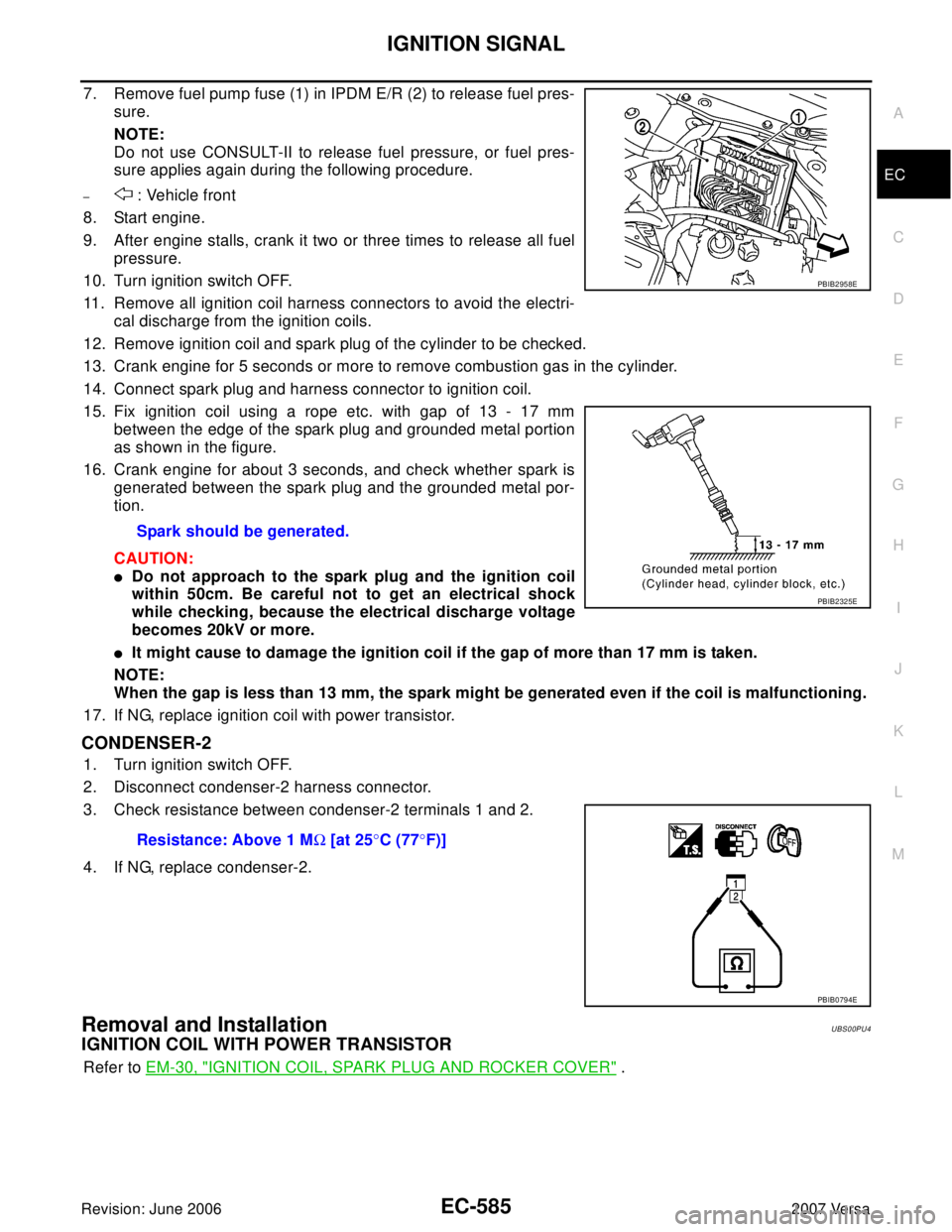
7. Remove fuel pump fuse (1) in IPDM E/R (2) to release fuel pres-
sure.
NOTE:
Do not use CONSULT-II to release fuel pressure, or fuel pres-
sure applies again during the following procedure.
– : Vehicle front
8. Start engine.
9. After engine stalls, crank it two or three times to release all fuel
pressure.
10. Turn ignition switch OFF.
11. Remove all ignition coil harness connectors to avoid the electri-
cal discharge from the ignition coils.
12. Remove ignition coil and spark plug of the cylinder to be checked.
13. Crank engine for 5 seconds or more to remove combustion gas in the cylinder.
14. Connect spark plug and harness connector to ignition coil.
15. Fix ignition coil using a rope etc. with gap of 13 - 17 mm
between the edge of the spark plug and grounded metal portion
as shown in the figure.
16. Crank engine for about 3 seconds, and check whether spark is
generated between the spark plug and the grounded metal por-
tion.
CAUTION:
�Do not approach to the spark plug and the ignition coil
within 50cm. Be careful not to get an electrical shock
while checking, because the electrical discharge voltage
becomes 20kV or more.
�It might cause to damage the ignition coil if the gap of more than 17 mm is taken.
NOTE:
When the gap is less than 13 mm, the spark might be generated even if the coil is malfunctioning.
17. If NG, replace ignition coil with power transistor.
CONDENSER-2
1. Turn ignition switch OFF.
2. Disconnect condenser-2 harness connector.
3. Check resistance between condenser-2 terminals 1 and 2.
4. If NG, replace condenser-2.
Removal and InstallationUBS00PU4
IGNITION COIL WITH POWER TRANSISTOR
Refer to EM-30, "IGNITION COIL, SPARK PLUG AND ROCKER COVER" . Spark should be generated.
PBIB2958E
PBIB2325E
Resistance: Above 1 MΩ [at 25°C (77°F)]
PBIB0794E
Page 1764 of 2896
SERVICE DATA AND SPECIFICATIONS (SDS)
EC-595
C
D
E
F
G
H
I
J
K
L
MA
EC
Revision: June 20062007 Versa
Camshaft Position Sensor (PHASE)UBS00PUJ
Refer to EC-333, "Component Inspection" .
Throttle Control MotorUBS00PUK
Fuel InjectorUBS00PUL
Fuel PumpUBS00PUM
Resistance [at 25°C (77°F)] Approximately 1 - 15Ω
Resistance [at 10 - 60°C (50 - 140°F)] 11.4 - 14.5Ω
Resistance [at 25°C (77°F)] Approximately 0.2 - 5.0Ω
Page 1871 of 2896
EM-62Revision: June 2006
CYLINDER HEAD
2007 Versa
CYLINDER HEADPFP:11041
On-Vehicle ServiceEBS00T6K
CHECKING COMPRESSION PRESSURE
1. Warm up engine thoroughly. Then, stop it.
2. Release fuel pressure. Refer to EC-81, "
FUEL PRESSURE RELEASE" .
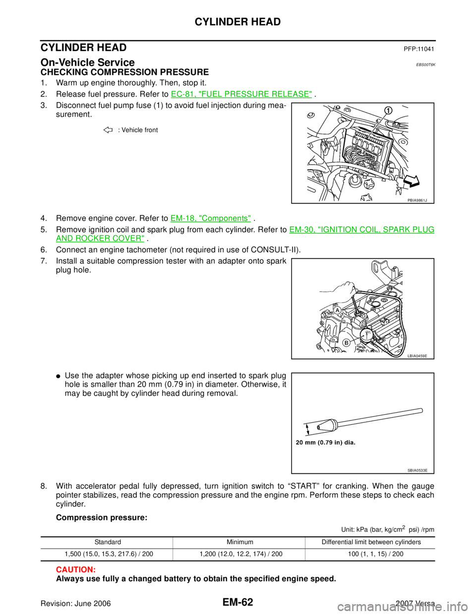
3. Disconnect fuel pump fuse (1) to avoid fuel injection during mea-
surement.
4. Remove engine cover. Refer to EM-18, "
Components" .
5. Remove ignition coil and spark plug from each cylinder. Refer to EM-30, "
IGNITION COIL, SPARK PLUG
AND ROCKER COVER" .
6. Connect an engine tachometer (not required in use of CONSULT-II).
7. Install a suitable compression tester with an adapter onto spark
plug hole.
�Use the adapter whose picking up end inserted to spark plug
hole is smaller than 20 mm (0.79 in) in diameter. Otherwise, it
may be caught by cylinder head during removal.
8. With accelerator pedal fully depressed, turn ignition switch to “START” for cranking. When the gauge
pointer stabilizes, read the compression pressure and the engine rpm. Perform these steps to check each
cylinder.
Compression pressure:
Unit: kPa (bar, kg/cm2 psi) /rpm
CAUTION:
Always use fully a changed battery to obtain the specified engine speed.
: Vehicle front
PBIA9861J
LBIA0459E
SBIA0533E
Standard Minimum Differential limit between cylinders
1,500 (15.0, 15.3, 217.6) / 200 1,200 (12.0, 12.2, 174) / 200 100 (1, 1, 15) / 200
Page 1958 of 2896

FL-1
FUEL SYSTEM
B ENGINE
CONTENTS
C
D
E
F
G
H
I
J
K
L
M
SECTION FL
A
FL
Revision: June 20062007 Versa PRECAUTIONS .......................................................... 2
Precautions for Supplemental Restraint System
(SRS) “AIR BAG” and “SEAT BELT PRE-TEN-
SIONER” .................................................................. 2
PREPARATION ........................................................... 3
Special Service Tools ............................................... 3
Commercial Service Tools ........................................ 3
FUEL SYSTEM ........................................................... 4
Checking Fuel Lines ................................................. 4
General Precautions ................................................ 4
FUEL LEVEL SENSOR UNIT, FUEL FILTER AND
FUEL PUMP ASSEMBLY ........................................... 5Components ............................................................. 5
Removal and Installation .......................................... 5
REMOVAL ............................................................. 5
INSPECTION AFTER REMOVAL ......................... 7
INSTALLATION ..................................................... 7
INSPECTION AFTER INSTALLATION .................. 8
FUEL TANK ................................................................ 9
Components ............................................................. 9
Removal and Installation .......................................... 9
REMOVAL ............................................................. 9
INSTALLATION ................................................... 12
INSPECTION AFTER INSTALLATION ................ 12
SERVICE DATA AND SPECIFICATIONS (SDS) ...... 13
Standard and Limit .................................................. 13
FUEL TANK ......................................................... 13
Page 1962 of 2896
FUEL LEVEL SENSOR UNIT, FUEL FILTER AND FUEL PUMP ASSEMBLY
FL-5
C
D
E
F
G
H
I
J
K
L
MA
FL
Revision: June 20062007 Versa
FUEL LEVEL SENSOR UNIT, FUEL FILTER AND FUEL PUMP ASSEMBLYPFP:17042
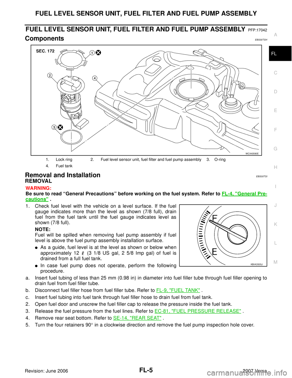
ComponentsEBS00TSH
Removal and InstallationEBS00TSI
REMOVAL
WA RN ING:
Be sure to read “General Precautions” before working on the fuel system. Refer to FL-4, "
General Pre-
cautions" .
1. Check fuel level with the vehicle on a level surface. If the fuel
gauge indicates more than the level as shown (7/8 full), drain
fuel from the fuel tank until the fuel gauge indicates level as
shown (7/8 full).
NOTE:
Fuel will be spilled when removing fuel pump assembly if fuel
level is above the fuel pump assembly installation surface.
�As a guide, fuel level is at the level as shown or below when
approximately 12 (3 1/8 US gal, 2 5/8 Imp gal) of fuel is
drained from a full fuel tank.
�In case fuel pump does not operate, perform the following
procedure.
a. Insert fuel tubing of less than 25 mm (0.98 in) in diameter into fuel filler tube through fuel filler opening to
drain fuel from fuel filler tube.
b. Disconnect fuel filler hose from fuel filler tube. Refer to FL-9, "
FUEL TANK" .
c. Insert fuel tubing into fuel tank through fuel filler hose to drain fuel from fuel tank.
2. Open fuel door and unscrew the fuel filler cap to release the pressure inside the fuel tank.
3. Release the fuel pressure from the fuel lines. Refer to EC-81, "
FUEL PRESSURE RELEASE" .
4. Remove rear seat bottom. Refer to SE-14, "
REAR SEAT" .
5. Turn the four retainers 90° in a clockwise direction and remove the fuel pump inspection hole cover.
1. Lock ring 2. Fuel level sensor unit, fuel filter and fuel pump assembly 3. O-ring
4. Fuel tank
WCIA0590E
KBIA3505J
Page 1963 of 2896
FL-6Revision: June 2006
FUEL LEVEL SENSOR UNIT, FUEL FILTER AND FUEL PUMP ASSEMBLY
2007 Versa
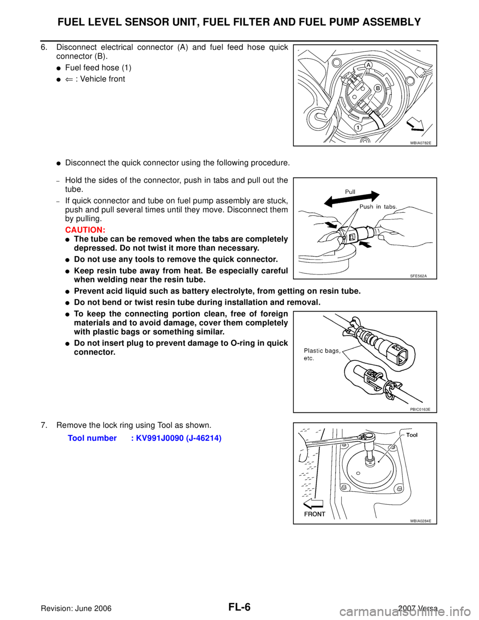
6. Disconnect electrical connector (A) and fuel feed hose quick
connector (B).
�Fuel feed hose (1)
�⇐ : Vehicle front
�Disconnect the quick connector using the following procedure.
–Hold the sides of the connector, push in tabs and pull out the
tube.
–If quick connector and tube on fuel pump assembly are stuck,
push and pull several times until they move. Disconnect them
by pulling.
CAUTION:
�The tube can be removed when the tabs are completely
depressed. Do not twist it more than necessary.
�Do not use any tools to remove the quick connector.
�Keep resin tube away from heat. Be especially careful
when welding near the resin tube.
�Prevent acid liquid such as battery electrolyte, from getting on resin tube.
�Do not bend or twist resin tube during installation and removal.
�To keep the connecting portion clean, free of foreign
materials and to avoid damage, cover them completely
with plastic bags or something similar.
�Do not insert plug to prevent damage to O-ring in quick
connector.
7. Remove the lock ring using Tool as shown.
WBIA0782E
SF E5 62 A
PBIC0163E
Tool number : KV991J0090 (J-46214)
WBIA0284E
Page 1964 of 2896
FUEL LEVEL SENSOR UNIT, FUEL FILTER AND FUEL PUMP ASSEMBLY
FL-7
C
D
E
F
G
H
I
J
K
L
MA
FL
Revision: June 20062007 Versa
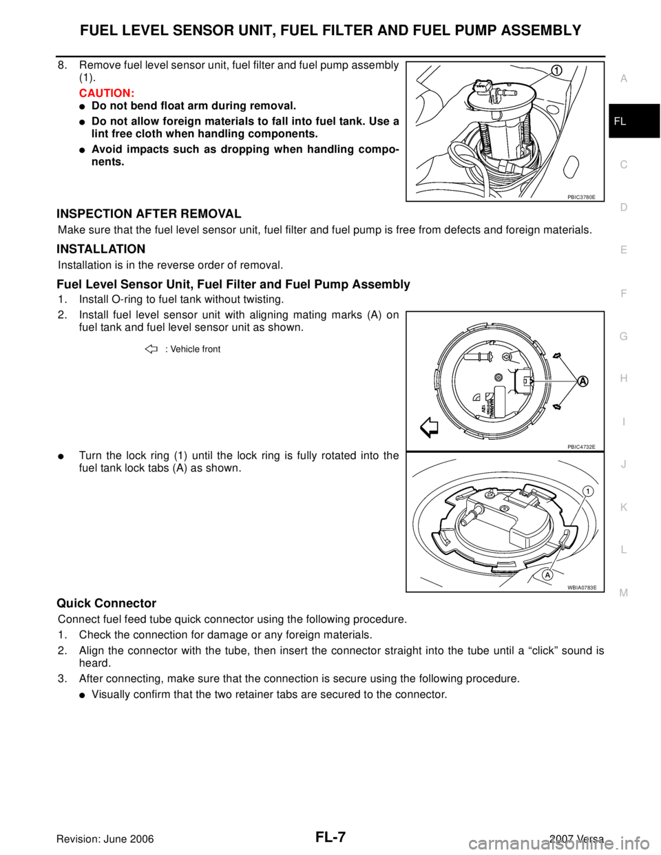
8. Remove fuel level sensor unit, fuel filter and fuel pump assembly
(1).
CAUTION:
�Do not bend float arm during removal.
�Do not allow foreign materials to fall into fuel tank. Use a
lint free cloth when handling components.
�Avoid impacts such as dropping when handling compo-
nents.
INSPECTION AFTER REMOVAL
Make sure that the fuel level sensor unit, fuel filter and fuel pump is free from defects and foreign materials.
INSTALLATION
Installation is in the reverse order of removal.
Fuel Level Sensor Unit, Fuel Filter and Fuel Pump Assembly
1. Install O-ring to fuel tank without twisting.
2. Install fuel level sensor unit with aligning mating marks (A) on
fuel tank and fuel level sensor unit as shown.
�Turn the lock ring (1) until the lock ring is fully rotated into the
fuel tank lock tabs (A) as shown.
Quick Connector
Connect fuel feed tube quick connector using the following procedure.
1. Check the connection for damage or any foreign materials.
2. Align the connector with the tube, then insert the connector straight into the tube until a “click” sound is
heard.
3. After connecting, make sure that the connection is secure using the following procedure.
�Visually confirm that the two retainer tabs are secured to the connector.
PBIC3780E
: Vehicle front
PBIC4732E
WBIA0783E