Page 809 of 2896

BR-26
FRONT DISC BRAKE
Revision: June 20062007 Versa
5. Check brake for drag.
6. Install tires to the vehicle.
Removal and Installation of Brake Caliper Assembly EFS006JQ
REMOVAL
1. Remove tires from vehicle.
2. Secure disc rotor using wheel nuts.
CAUTION:
Put matching marks on wheel hub assembly and disc rotor, if it is necessary to remove disc rotor.
3. Drain brake fluid. Refer to BR-9, "
Drain and Refill" .
4. Remove union bolt, and then remove brake hose from caliper
assembly.
5. Remove torque member mounting bolts from torque member,
and remove caliper assembly from vehicle.
INSTALLATION
1. Install caliper assembly to vehicle, and tighten mounting bolts to the specified torque. Refer to BR-24,
"Components" .
CAUTION:
Before installing torque member to vehicle, wipe oil and grease on mounting surface of steering
knuckle and torque member.
2. Install brake hose to caliper assembly. Refer to BR-11, "
Hydraulic Circuit" .
3. Refill with new brake fluid and bleed air. Refer to BR-10, "
Bleeding Brake System" .
4. Check front disc brake for drag.
5. Install tires to the vehicle.
Disassembly and Assembly of Brake Caliper Assembly EFS006JR
NOTE:
Do not remove torque member, brake pads, shims and pad retainers, when disassembling or assembling cyl-
inder body.
DISASSEMBLY
1. Remove caliper assembly from vehicle. Refer to BR-26,
"REMOVAL" .
2. Remove sliding pin bolts from cylinder body, and remove pads,
shims and pad retainers from torque member, if necessary.
CAUTION:
When removing pad retainer from torque member, lift the
pad retainer in the direction shown by arrow, so as not to
deform it.
WFIA0524E
SBR5 56 E
Page 810 of 2896

FRONT DISC BRAKE
BR-27
C
D
E
G
H
I
J
K
L
MA
B
BR
Revision: June 20062007 Versa
3. Remove sliding pins and sliding pin boots from torque member.
4. Place a wooden block as shown, and blow air from union bolt
mounting hole to remove piston and piston boot.
CAUTION:
Do not get fingers caught in the piston.
5. Remove piston seal with a flat-bladed screwdriver.
CAUTION:
Be careful not to damage the inner wall of cylinder.
INSPECTION AFTER DISASSEMBLY
Cylinder Body
Check the inner wall of cylinder for corrosion, wear, and damage. Replace cylinder body as necessary.
CAUTION:
Clean cylinder body using new brake fluid. Never use mineral oils such as gasoline or kerosene.
Torque Member
Check for wear, cracks, and damage. Replace torque member as necessary..
Piston
Check piston surface for corrosion, wear, and damage. Replace piston as necessary.
CAUTION:
The piston sliding surface is plated. Do not polish with sandpaper.
Sliding Pin, Sliding Pin Bolt, and Sliding Pin Boot
Check sliding pins, sliding pin bolts and sliding pin boots for wear, damage, and cracks. Replace applicable
part as necessary.
ASSEMBLY
CAUTION:
When assembling, use only specified rubber lubricant.
1. Apply polyglycol ether based lubricant to new piston seal and
install them to cylinder body.
WFIA0525E
SFIA2277E
SFIA2278E
Page 811 of 2896

BR-28
FRONT DISC BRAKE
Revision: June 20062007 Versa
2. Apply rubber grease to piston boot and apply brake fluid to pis-
ton. Cover the piston end with piston boot, and install cylinder-
side lip on piston boot properly into groove on cylinder body.
3. Press piston into cylinder body by hand to assemble piston-side
lip on piston boot properly into a groove on piston.
CAUTION:
Press piston evenly and change pressing point to prevent
inner wall of cylinder from being rubbed.
4. Install sliding pins and sliding pin boots to the torque member.
5. If pads, shims and pad retainers were removed, install them to torque member. Refer to BR-25, "
INSTAL-
LATION" .
6. Install cylinder body to torque member.
7. Install sliding pin bolts.
8. Install caliper assembly to vehicle. Refer to BR-26, "
INSTALLATION" .
9. Tighten sliding pin bolts to specified torque. Refer to BR-24, "
Components" .
DISC ROTOR INSPECTION
Visual Inspection
Check surfaces of disc rotor for uneven wear, cracks, and serious damage. Replace applicable part as neces-
sary.
Runout Inspection
1. Using wheel nuts, secure disc rotor to wheels hub 2 or more positions.
2. Using a dial indicator, check runout.
CAUTION:
Make sure that wheel bearing axial end play is within the
specifications before measuring runout. Refer to FA X -5 ,
"FRONT WHEEL BEARING INSPECTION" .
3. If runout is outside the limit, find the minimum runout point by
shifting the mounting positions of disc rotor and wheel hub by
one hole.
SFIA3074E
SFIA2279E
Runout limit : 0.04 mm (0.0016 in) or less
[Measured at 10.0 mm (0.394 in) inside
the disc edge]
SBR0 19 B
Page 813 of 2896
BR-30
REAR DRUM BRAKE
Revision: June 20062007 Versa
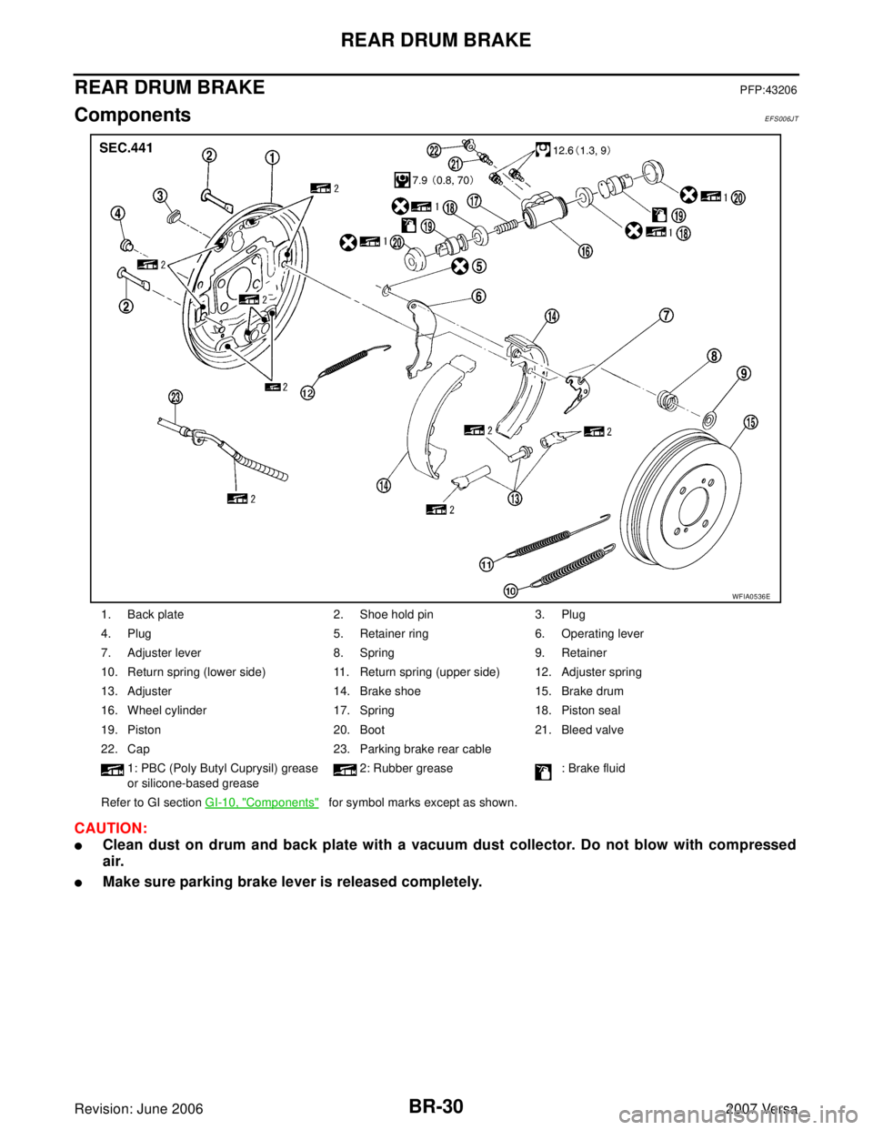
REAR DRUM BRAKEPFP:43206
ComponentsEFS006JT
CAUTION:
�Clean dust on drum and back plate with a vacuum dust collector. Do not blow with compressed
air.
�Make sure parking brake lever is released completely.
1. Back plate 2. Shoe hold pin 3. Plug
4. Plug 5. Retainer ring 6. Operating lever
7. Adjuster lever 8. Spring 9. Retainer
10. Return spring (lower side) 11. Return spring (upper side) 12. Adjuster spring
13. Adjuster 14. Brake shoe 15. Brake drum
16. Wheel cylinder 17. Spring 18. Piston seal
19. Piston 20. Boot 21. Bleed valve
22. Cap 23. Parking brake rear cable
1: PBC (Poly Butyl Cuprysil) grease
or silicone-based grease2: Rubber grease : Brake fluid
Refer to GI section GI-10, "
Components" for symbol marks except as shown.
WFIA0536E
Page 815 of 2896

Wheel Cylinder Leakage Inspecti")
BR-32
REAR DRUM BRAKE
Revision: June 20062007 Versa
Drum Inner Diameter Inspection
Check inner diameter of brake drum.
Measurement area: lining contact surface (center)
Wheel Cylinder Leakage Inspection
�Check wheel cylinder for brake fluid leakage.
�Check for wear, damage, and looseness. If any non-standard
condition is found, replace it.
Other Inspections
Check the following:
�Inside of the drum for excessive wear, damage, and cracks.
�Lining for excessive wear, damage, and peeling.
�Shoe sliding surface for excessive wear and damage.
�Return spring for sagging.
�Check back plate for damage, cracks, and deformation. Replace back plate as necessary.
Replace applicable part as necessary.
INSTALLATION
1. If operating lever (C) if removed.
a. Install operating lever (C) to brake shoe.
b. Install retainer ring (A) to operating lever (C), and crimp them
until their contact points (B) are met.
�Retainer ring (A)
�Contact point (B)
�Operating lever (C)
�Pin (D)Standard inner diameter : 228.6 mm (9.000 in) dia.
Repair limit inner diameter : 230.0 mm (9.055 in) dia.
SBR0 22 A
WFIA0528E
SFIA3075E
Page 816 of 2896
 to brake shoes slid-
ing surfaces (the shaded areas) and other parts on the back")
REAR DRUM BRAKE
BR-33
C
D
E
G
H
I
J
K
L
MA
B
BR
Revision: June 20062007 Versa
2. Apply NISSAN brake grease (KRF0000005) to brake shoes slid-
ing surfaces (the shaded areas) and other parts on the back
plate as indicated by arrows.
3. Apply NISSAN brake grease (KRF00 00005) to screw and con-
firm the difference between right and left wheel for assembling
when disassembled.
4. Assemble the shoe, adjuster, adjuster lever and springs to the shoe assembly.
5. Connect the parking brake rear cable to the operating lever.
6. Install the shoe assembly. After assembly, be sure that each part is installed properly.
CAUTION:
Do not damage the wheel cylinder piston boot.
7. Install the brake drum.
8. Depress brake pedal for several times (approximately 2, 3 times).
9. Adjust clearance of brake shoe. Refer to PB-4, "
ADJUSTMENT" .
10. Install tires to the vehicle.
Removal and Installation of Wheel CylinderEFS006JV
REMOVAL
1. Drain brake fluid. Refer to BR-9, "Drain and Refill" .
2. Remove the rear brake shoe assembly. Refer to BR-31, "
Removal and Installation of Drum Brake Assem-
bly" .
3. Remove the brake tube from the wheel cylinder.
4. Remove bolts on the wheel cylinder, and then remove wheel cylinder from the back plate.
INSTALLATION
�Installation is the reverse order of removal. Tighten bolts to the specified torque. Refer to BR-30, "Compo-
nents" .
�Refill with new brake fluid and bleed air. Refer to BR-10, "Bleeding Brake System" .
WFIA0529E
Right rear
wheelThread cutting
direction: Right-hand screw
Left rear
wheelThread cutting
direction: Left-hand screw
SFIA3076E
Page 817 of 2896
BR-34
REAR DRUM BRAKE
Revision: June 20062007 Versa
Disassembly and Assembly of Wheel CylinderEFS006JW
DISASSEMBLY
1. Remove boots at the right and left of the wheel cylinder, and pull
out the pistons from cylinder.
2. Remove piston from piston cup.
INSPECTION AFTER DISASSEMBLY
Check the pistons, piston cups, and inner wall of the cylinder for wear, corrosion, and damage. If malfunction
is detected, replace it.
ASSEMBLY
CAUTION:
�Do not use Nissan rubber grease (KRE0000010, KRE000001001) during assembly.
�When inserting the piston, be careful not to scratch the cylinder.
1. Apply brake fluid to the piston sliding surface on the wheel cylinder.
2. Apply Nissan rubber lubricant (KRE1200030) to the piston cups
and piston boots and assemble as shown.
SFIA3077E
SFIA3078E
Page 818 of 2896

BR-35
C
D
E
G
H
I
J
K
L
MA
B
BR
Revision: June 20062007 Versa
SERVICE DATA AND SPECIFICATIONS (SDS)PFP:00030
General SpecificationsEFS006JX
Brake PedalEFS006JY
Un")
SERVICE DATA AND SPECIFICATIONS (SDS)
BR-35
C
D
E
G
H
I
J
K
L
MA
B
BR
Revision: June 20062007 Versa
SERVICE DATA AND SPECIFICATIONS (SDS)PFP:00030
General SpecificationsEFS006JX
Brake PedalEFS006JY
Unit: mm (in)
Check ValveEFS006JZ
Brake BoosterEFS006K0
Vacuum type
Front Disc Brake EFS006K1
Unit: mm (in) Front brake Brake model CLZ25VA
Cylinder bore diameter 57.2 mm (2.252 in)
Pad
Length × width × thickness11 5 . 0 m m × 41.0 mm × 9.5 mm
(4.528 in × 1.614 in × 0.374 in)
Rotor outer diameter × thickness 260 mm × 22.0 mm (10.24 in × 0.866 in)
Rear brake Brake model LT20D
Cylinder bore diameter 15.87 mm (0.625 in)
Lining
Length × width × thickness194.1 mm × 30.0 mm × 4.0 mm
(7.642 in × 1.181 in × 0.157 in)
Drum outer diameter 228.6 mm (9.000 in)
Master cylinder Cylinder bore diameter 22.22 mm (0.875 in)
Control valve Valve model Electric brake force distribution
Brake booster Booster model C255
Diaphragm diameter 255 mm (10.04 in)
Recommended brake fluid Refer to MA-11, "
RECOMMENDED FLUIDS AND LUBRICANTS" .
Brake pedal free height (from dash panel top surface)A/T, CVT model 172.4 - 182.4 (6.79 - 7.18)
M/T model 162.3 - 172.3 (6.39 - 6.78)
Brake pedal depressed height
[under a force of 490 N (50 kg-f, 110 lb-f) with the engine running]A/T, CVT model 98 (3.86) or more
M/T model 90 (3.54) or more
Clearance between brake pedal lever and the threaded end of stop lamp switch 0.74 - 1.96 (0.0291 - 0.0772)
Pedal play3 - 11 (0.12 - 0.43)
Vacuum leakage
[at vacuum of – 66.7 kPa (– 500 mmHg, – 19.69 inHg]Within 1.3 kPa (10 mmHg, 0.39 inHg) of vacuum for 15 seconds
Vacuum leakage
[at vacuum of – 66.7 kPa (– 500 mmHg, –19.69 inHg)]Within 3.3 kPa (25 mmHg, 0.98 inHg) of vacuum for 15 seconds
Input rod installation standard dimension 154 - 161 mm (6.06 - 6.34 in)
Brake modelCLZ25VA
Brake padStandard thickness (new) 9.5 (0.374)
Repair limit thickness 2.0 (0.079)
Disc rotorStandard thickness (new) 24.0 (0.945)
Repair limit thickness 22.0 (0.866)
Runout limit 0.04 (0.0016)
Maximum uneven wear (mea-
sured at 8 positions)0.02 mm (0.0008 in) or less