Page 796 of 2896
BRAKE TUBE AND HOSE
BR-13
C
D
E
G
H
I
J
K
L
MA
B
BR
Revision: June 20062007 Versa
1. Check brake hose, tube, and connections for fluid leaks, damage, twist, deformation, contact with other
parts, and loose connections.
2. While depressing pedal under a force of 785 N (80 kg-f, 177 lb-f) with the engine running for approxi-
mately 5 seconds, check for fluid leak from each part.
Page 797 of 2896

BR-14
BRAKE MASTER CYLINDER
Revision: June 20062007 Versa
BRAKE MASTER CYLINDERPFP:46010
On-Board InspectionEFS006JF
LEAK INSPECTION
�Check for leaking in a master cylinder installation surface, a reservoir tank installation surface, and brake
tube connections.
Removal and InstallationEFS006JG
CAUTION:
Be careful not to splash brake fluid on painted areas; it may cause paint damage. If brake fluid is
splashed on painted areas, immediately wipe them with cloth and wash it away with water.
REMOVAL
1. Drain brake fluid. Refer to BR-9, "Drain and Refill" .
2. Remove battery. Refer to SC-9, "
Removal and Installation" .
3. Remove air duct. Refer to EM-16, "
Removal and Installation" .
4. Remove air cleaner. Refer to EM-16, "
Removal and Installation" .
5. Disconnect brake fluid level switch harness connector.
6. Using a flare nut wrench, remove brake tube from master cylinder.
7. Remove master cylinder assembly nuts, and remove master cylinder assembly from vehicle..
INSTALLATION
CAUTION:
�Refill using recommended brake fluid. Refer to MA-11, "RECOMMENDED FLUIDS AND LUBRI-
CANTS" .
�Never reuse drained brake fluid.
�Check if the rod of primary piston has dust or scratches.
1. Install master cylinder to brake booster assembly, and tighten nuts to the specified torque. Refer to BR-20,
"Removal and Installation" .
CAUTION:
�Do not damage or strain rod of primary piston.
�Apply silicone grease for O-ring, primary piston rod and
to inside of booster.
2. Install brake tube to master cylinder, and temporarily tighten the flare nuts on the brake tube to master cyl-
inder by hand.
3. Install brake tube to brake hose, then tighten flare nut to the specified torque using a flare nut torque
wrench. Refer to BR-11, "
Hydraulic Circuit" .
4. Connect brake fluid level switch harness connector.
5. Refill new brake fluid and bleed air. Refer toBR-10, "
Bleeding Brake System" .
SFIA2614E
Page 798 of 2896

BRAKE MASTER CYLINDER
BR-15
C
D
E
G
H
I
J
K
L
MA
B
BR
Revision: June 20062007 Versa
Disassembly and AssemblyEFS006JH
COMPONENTS
DISASSEMBLY
CAUTION:
While working, cover primary piston rod with cloth to prevent it from being damaged.
1. Secure flange of cylinder body in vise as shown.
CAUTION:
�Use copper plate or cloth to cover flange when securing
in vise.
�When securing master cylinder assembly in a vise, be
sure not to over-tighten.
2. Using a pin-punch [commercial service tool: diameter approx. 4
mm (0.16 in)], remove pin from reservoir tank.
3. Remove master cylinder assembly from vise.
4. Remove reservoir tank and grommet from cylinder body.
1. Reservoir cap 2. Oil filter 3. Reservoir tank
4. Grommet 5. Piston stopper 6. Cylinder body
7. Pin 8. Brake fluid level switch connector 9. O-ring
10. Secondary piston assembly 11. Primary piston assembly 12. Plate
13. Guide assembly 14. Snap ring
:PBC (Poly Butyl Cuprysil) grease
or silicone-based grease:Brake fluid
Refer to GI section GI-10, "
Components" for symbol marks unless shown.
SFIA3094E
WFIA0514E
WFIA0515E
Page 799 of 2896

BR-16
BRAKE MASTER CYLINDER
Revision: June 20062007 Versa
5. While pushing primary piston, remove piston stopper through
secondary tank boss hole in the cylinder body.
6. Remove snap ring with pushing primary piston.
CAUTION:
Be careful not to pop out piston.
7. Holding rod of primary piston, remove primary piston assembly,
plate and guide assembly by pulling straight to prevent piston
cup from being caught by the inner wall of cylinder.
8. Remove plate and guide assembly from primary piston.
CAUTION:
Be careful not to damage rod from the inner wall of plate.
9. Tap flange using a soft block such as wood, and carefully pull
secondary piston assembly straight out to prevent cylinder inner
wall from being damaged.
INSPECTION AFTER DISASSEMBLY
Cylinder Body
�Check the inner wall of cylinder for damage, wear, corrosion, and pin holes. Replace cylinder body if nec-
essary.
ASSEMBLY
CAUTION:
�Never use mineral oils such as kerosene or gasoline during the cleaning and assembly processes.
�Make sure that there is no foreign material such as dirt and dust on the inner wall of cylinder, pis-
ton, and piston cup. Be careful not to damage parts with a service tool when assembling.
�Do not drop parts. If a part is dropped, do not use it.
1. Apply brake fluid to the inner wall of cylinder body, primary pis-
ton assembly and secondary piston assembly.
2. Insert secondary piston and primary piston assembly into cylin-
der body in this order.
CAUTION:
�Pay attention to the orientation of piston cup, and insert
straight to prevent cup from being caught by the inner
wall of cylinder.
�Always replace inner kit as a set.
WFIA0516E
BRA0561DWFIA0517E
WFIA0518E
SBR0 89 C
Page 800 of 2896

BRAKE MASTER CYLINDER
BR-17
C
D
E
G
H
I
J
K
L
MA
B
BR
Revision: June 20062007 Versa
3. Set the slit of secondary piston towards the piston stopper
mounting hole of cylinder body while pushing in the primary pis-
ton. Then install the piston stopper through the slit of secondary
piston.
4. Insert plate and guide assembly into cylinder body.
CAUTION:
�Be careful not to damage rod of primary piston.
�Pay attention to the orientation of guide assembly.
�Do not drop O-ring.
�Be careful the guide and/or plate are not inserted at an
angle to cylinder inner wall.
5. Be careful not to damage rod of primary piston with the cloth.
Then insert snap ring to cylinder body while pushing primary pis-
ton.
CAUTION:
Make sure that snap ring is securely engaged in cylinder
body inner diameter groove.
6. Apply brake fluid to a grommet, and press it into reservoir tank to install.
7. Install reservoir tank to cylinder body.
CAUTION:
Pay attention to the orientation of reservoir tank. Make sure
reservoir tank is fully seated on master cylinder.
WFIA0516E
SFIA1469E
WFIA0517E
WFIA0519E
Page 803 of 2896
BR-20
BRAKE BOOSTER
Revision: June 20062007 Versa
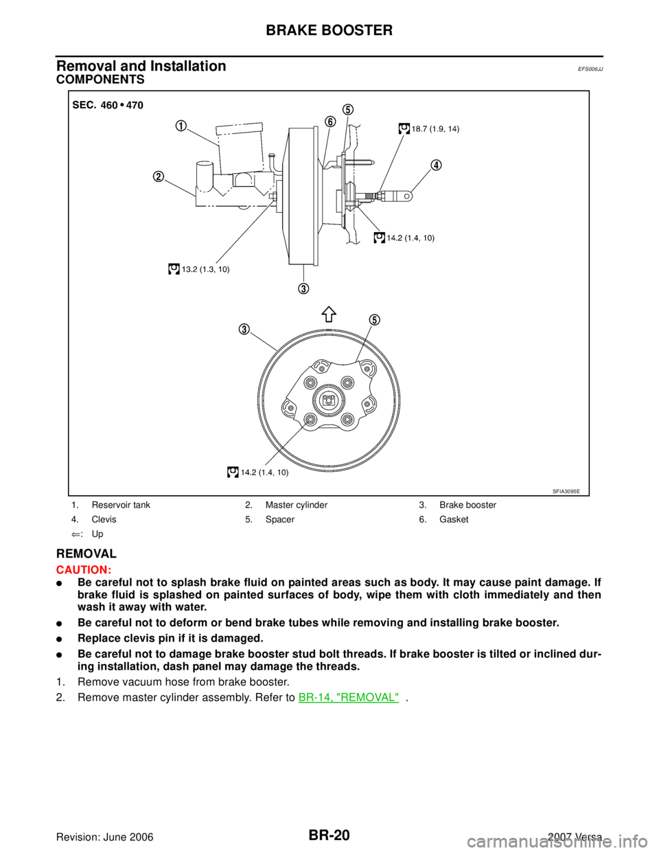
Removal and Installation EFS006JJ
COMPONENTS
REMOVAL
CAUTION:
�Be careful not to splash brake fluid on painted areas such as body. It may cause paint damage. If
brake fluid is splashed on painted surfaces of body, wipe them with cloth immediately and then
wash it away with water.
�Be careful not to deform or bend brake tubes while removing and installing brake booster.
�Replace clevis pin if it is damaged.
�Be careful not to damage brake booster stud bolt threads. If brake booster is tilted or inclined dur-
ing installation, dash panel may damage the threads.
1. Remove vacuum hose from brake booster.
2. Remove master cylinder assembly. Refer to BR-14, "
REMOVAL" .
1. Reservoir tank 2. Master cylinder 3. Brake booster
4. Clevis 5. Spacer 6. Gasket
⇐:Up
SFIA3095E
Page 807 of 2896
BR-24
FRONT DISC BRAKE
Revision: June 20062007 Versa
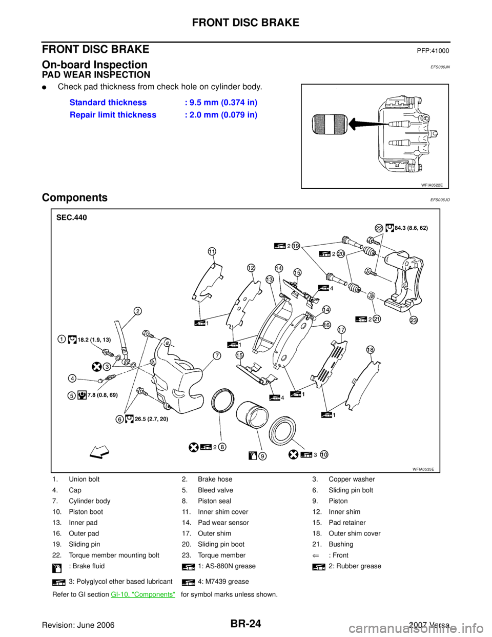
FRONT DISC BRAKEPFP:41000
On-board InspectionEFS006JN
PAD WEAR INSPECTION
�Check pad thickness from check hole on cylinder body.
ComponentsEFS006JO
Standard thickness : 9.5 mm (0.374 in)
Repair limit thickness : 2.0 mm (0.079 in)
WFIA0522E
1. Union bolt 2. Brake hose 3. Copper washer
4. Cap 5. Bleed valve 6. Sliding pin bolt
7. Cylinder body 8. Piston seal 9. Piston
10. Piston boot 11. Inner shim cover 12. Inner shim
13. Inner pad 14. Pad wear sensor 15. Pad retainer
16. Outer pad 17. Outer shim 18. Outer shim cover
19. Sliding pin 20. Sliding pin boot 21. Bushing
22. Torque member mounting bolt 23. Torque member⇐: Front
: Brake fluid 1: AS-880N grease 2: Rubber grease
3: Polyglycol ether based lubricant 4: M7439 grease
Refer to GI section GI-10, "
Components" for symbol marks unless shown.
WFIA0535E
Page 808 of 2896

FRONT DISC BRAKE
BR-25
C
D
E
G
H
I
J
K
L
MA
B
BR
Revision: June 20062007 Versa
CAUTION:
�Clean dust on caliper and brake pad with a vacuum dust collector. Do not blow with compressed
air.
�While removing brake pad or cylinder body, do not depress brake pedal because piston will pop
out.
�It is not necessary to remove torque member mounting bolts and brake hose except for disassem-
bly or replacement of caliper assembly. In this case, hang cylinder body with a wire so that brake
hose is not under tension.
�Do not damage piston boot.
�If any shim is subject to serious corrosion, replace it with a new one.
�Keep rotor free from brake fluid.
�When replacing brake pad, replace shim with a new one.
Removal and Installation of Brake PadEFS006JP
REMOVAL
1. Remove tires from vehicle.
2. Remove sliding pin bolt (lower side).
3. Hang cylinder body with a wire, and remove pads, shims and
pad retainers from torque member.
CAUTION:
When removing pad retainer from torque member, lift pad
retainer in the direction shown by arrow, so as not to
deform it.
INSTALLATION
1. Apply AS-880N grease or equivalent to the shims. Install shims to pads.
CAUTION:
Securely install shims according to mounting direction of pads.
2. Apply M7439 grease or equivalent to pad contact surface on pad retainers. Install pad retainers and pads
to the torque member.
CAUTION:
�When installing pad retainer, attach it firmly so that it is
not lifted up from torque member, as shown.
3. Install cylinder body to torque member.
NOTE:
Use a disc brake piston tool (commercial service tool) to easily press to piston in.
CAUTION:
Check the brake fluid level in the reservoir tank for fluid level because brake fluid returns to mas-
ter cylinder reservoir tank when pressing piston in.
4. Install lower sliding pin bolt (lower side), and tighten it to the specified torque. Refer to BR-24, "
Compo-
nents" .
SBR5 56 E
PFIA0273E