Page 367 of 2896
AT-354
ASSEMBLY
Revision: June 20062007 Versa
ASSEMBLYPFP:00000
Assembly (1)UCS005WG
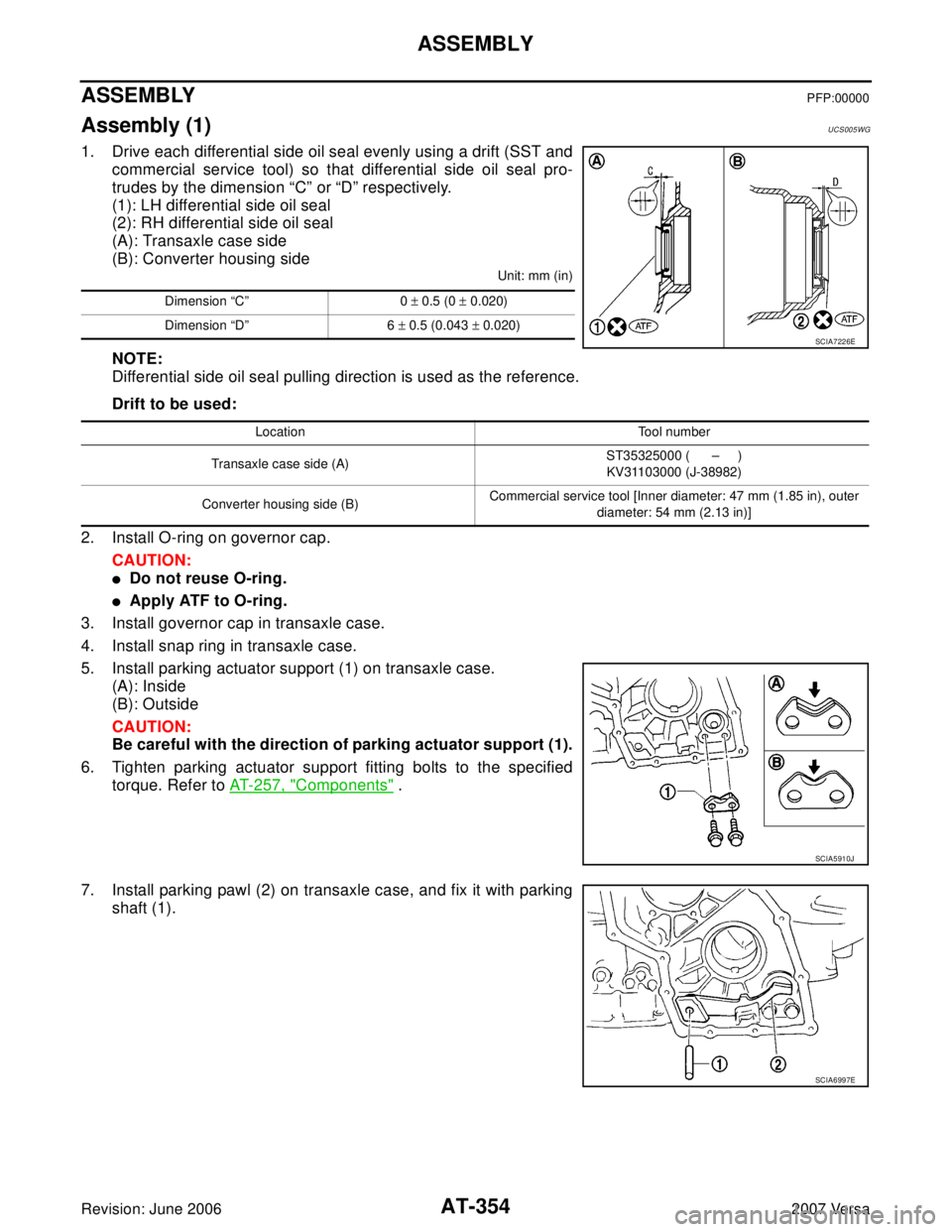
1. Drive each differential side oil seal evenly using a drift (SST and
commercial service tool) so that differential side oil seal pro-
trudes by the dimension “C” or “D” respectively.
(1): LH differential side oil seal
(2): RH differential side oil seal
(A): Transaxle case side
(B): Converter housing side
Unit: mm (in)
NOTE:
Differential side oil seal pulling direction is used as the reference.
Drift to be used:
2. Install O-ring on governor cap.
CAUTION:
�Do not reuse O-ring.
�Apply ATF to O-ring.
3. Install governor cap in transaxle case.
4. Install snap ring in transaxle case.
5. Install parking actuator support (1) on transaxle case.
(A): Inside
(B): Outside
CAUTION:
Be careful with the direction of parking actuator support (1).
6. Tighten parking actuator support fitting bolts to the specified
torque. Refer to AT-257, "
Components" .
7. Install parking pawl (2) on transaxle case, and fix it with parking
shaft (1).
Dimension “C” 0 ± 0.5 (0 ± 0.020)
Dimension “D” 6 ± 0.5 (0.043 ± 0.020)
SCIA7226E
Location Tool number
Transaxle case side (A)ST35325000 ( – )
KV31103000 (J-38982)
Converter housing side (B)Commercial service tool [Inner diameter: 47 mm (1.85 in), outer
diameter: 54 mm (2.13 in)]
SCIA5910J
SCIA6997E
Page 374 of 2896
ASSEMBLY
AT-361
D
E
F
G
H
I
J
K
L
MA
B
AT
Revision: June 20062007 Versa
�Completely remove all moisture, oil and old sealant, etc. from the transaxle case and side cover
mounting surfaces.
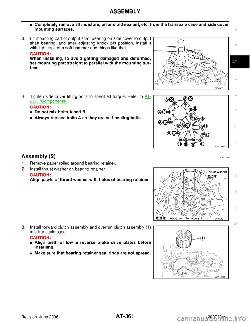
3. Fit mounting part of output shaft bearing on side cover to output
shaft bearing, and after adjusting knock pin position, install it
with light taps of a soft hammer and things like that.
CAUTION:
When installing, to avoid getting damaged and deformed,
set mounting part straight to parallel with the mounting sur-
face.
4. Tighten side cover fitting bolts to specified torque. Refer to AT-
257, "Components" .
CAUTION:
�Do not mix bolts A and B.
�Always replace bolts A as they are self-sealing bolts.
Assembly (2)UCS005WI
1. Remove paper rolled around bearing retainer.
2. Install thrust washer on bearing retainer.
CAUTION:
Align pawls of thrust washer with holes of bearing retainer.
3. Install forward clutch assembly and overrun clutch assembly (1)
into transaxle case.
CAUTION:
�Align teeth of low & reverse brake drive plates before
installing.
�Make sure that bearing retainer seal rings are not spread.
SAT4 4 2D
SCIA7939E
SAT3 5 4D
SCIA5900J
Page 385 of 2896
AT-372
ASSEMBLY
Revision: June 20062007 Versa
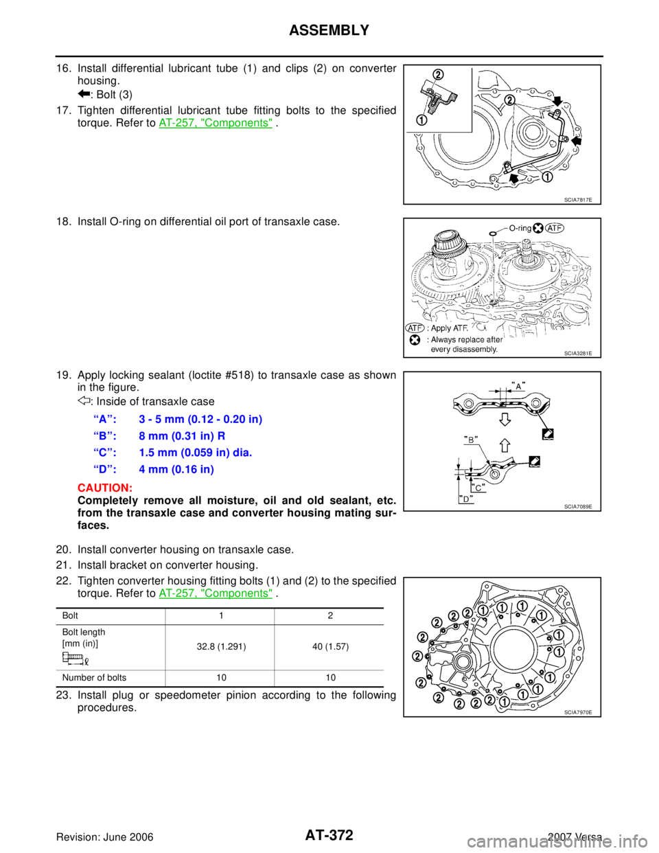
16. Install differential lubricant tube (1) and clips (2) on converter
housing.
: Bolt (3)
17. Tighten differential lubricant tube fitting bolts to the specified
torque. Refer to AT-257, "
Components" .
18. Install O-ring on differential oil port of transaxle case.
19. Apply locking sealant (loctite #518) to transaxle case as shown
in the figure.
: Inside of transaxle case
CAUTION:
Completely remove all moisture, oil and old sealant, etc.
from the transaxle case and converter housing mating sur-
faces.
20. Install converter housing on transaxle case.
21. Install bracket on converter housing.
22. Tighten converter housing fitting bolts (1) and (2) to the specified
torque. Refer to AT-257, "
Components" .
23. Install plug or speedometer pinion according to the following
procedures.
SCIA7817E
SCIA3281E
“A”: 3 - 5 mm (0.12 - 0.20 in)
“B”: 8 mm (0.31 in) R
“C”: 1.5 mm (0.059 in) dia.
“D”: 4 mm (0.16 in)
SCIA7089E
Bolt 1 2
Bolt length
[mm (in)]
32.8 (1.291) 40 (1.57)
Number of bolts 10 10
SCIA7970E
Page 387 of 2896
AT-374
ASSEMBLY
Revision: June 20062007 Versa
26. Install lip seals (1) for band servo oil holes on transaxle case.
27. Install control valve assembly on transaxle case.
a. Install O-ring on terminal body.
CAUTION:
�Do not reuse O-ring.
�Apply ATF to O-ring.
b. Insert manual valve into control valve assembly.
CAUTION:
Be careful not to drop manual valve.
c. Set manual shaft in “N” position.
d. Install control valve assembly on transaxle case while aligning
manual valve (2) with manual plate (1).
e. Install terminal body (2) into transaxle case by pushing it.
f. Install snap ring (1) to terminal body (2).
g. Tighten bolts A , B and C to the specified torque. Refer to AT-257, "
Components" .
SCIA5895J
SCIA3999E
SCIA7090E
SCIA6030J
Page 388 of 2896
ASSEMBLY
AT-375
D
E
F
G
H
I
J
K
L
MA
B
AT
Revision: June 20062007 Versa
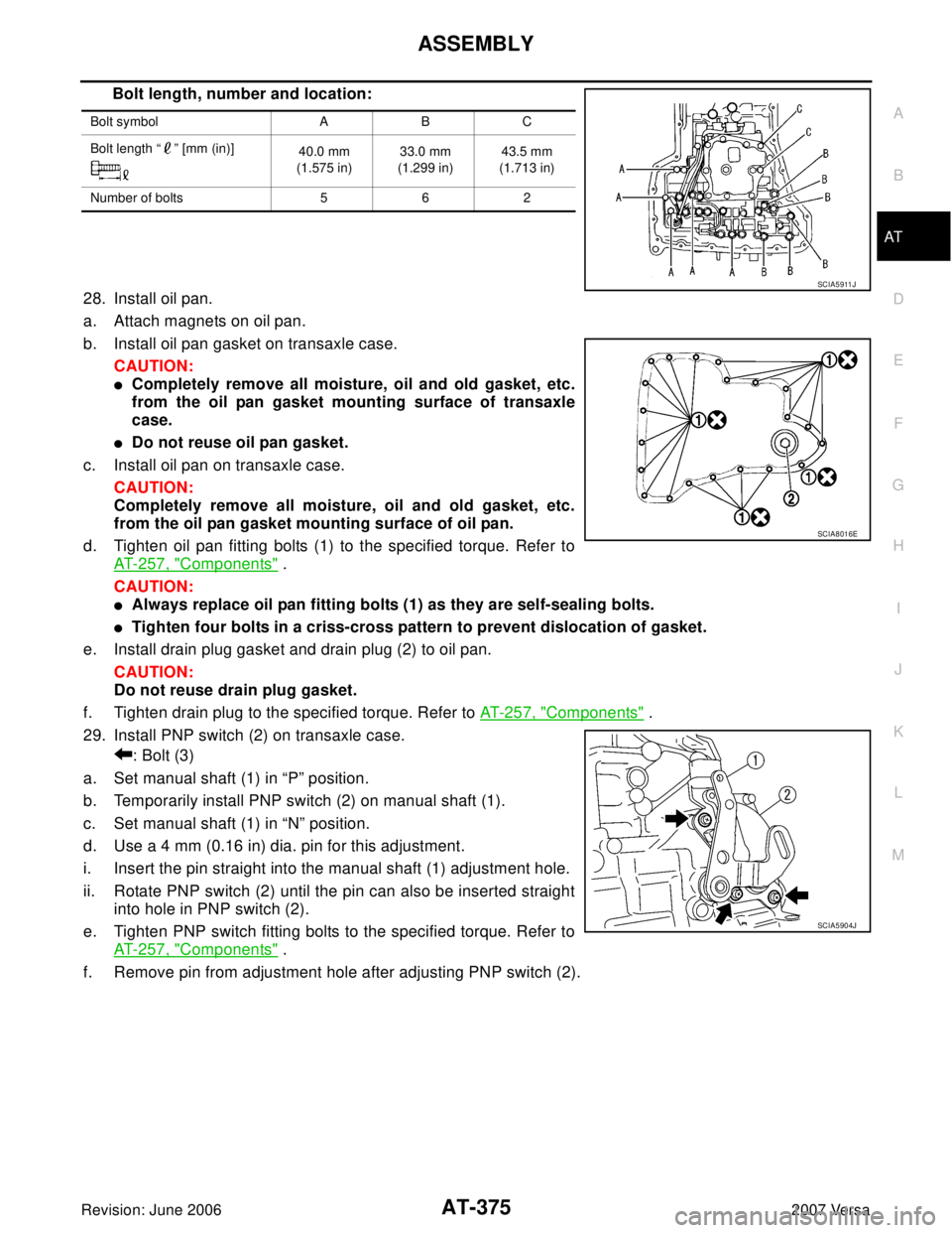
Bolt length, number and location:
28. Install oil pan.
a. Attach magnets on oil pan.
b. Install oil pan gasket on transaxle case.
CAUTION:
�Completely remove all moisture, oil and old gasket, etc.
from the oil pan gasket mounting surface of transaxle
case.
�Do not reuse oil pan gasket.
c. Install oil pan on transaxle case.
CAUTION:
Completely remove all moisture, oil and old gasket, etc.
from the oil pan gasket mounting surface of oil pan.
d. Tighten oil pan fitting bolts (1) to the specified torque. Refer to
AT-257, "
Components" .
CAUTION:
�Always replace oil pan fitting bolts (1) as they are self-sealing bolts.
�Tighten four bolts in a criss-cross pattern to prevent dislocation of gasket.
e. Install drain plug gasket and drain plug (2) to oil pan.
CAUTION:
Do not reuse drain plug gasket.
f. Tighten drain plug to the specified torque. Refer to AT- 2 5 7 , "
Components" .
29. Install PNP switch (2) on transaxle case.
: Bolt (3)
a. Set manual shaft (1) in “P” position.
b. Temporarily install PNP switch (2) on manual shaft (1).
c. Set manual shaft (1) in “N” position.
d. Use a 4 mm (0.16 in) dia. pin for this adjustment.
i. Insert the pin straight into the manual shaft (1) adjustment hole.
ii. Rotate PNP switch (2) until the pin can also be inserted straight
into hole in PNP switch (2).
e. Tighten PNP switch fitting bolts to the specified torque. Refer to
AT-257, "
Components" .
f. Remove pin from adjustment hole after adjusting PNP switch (2).
Bolt symbol A B C
Bolt length “ ” [mm (in)]
40.0 mm
(1.575 in)33.0 mm
(1.299 in)43.5 mm
(1.713 in)
Number of bolts 5 6 2
SCIA5 911 J
SCIA8016E
SCIA5904J
Page 395 of 2896

AT-382
SERVICE DATA AND SPECIFICATIONS (SDS)
Revision: June 20062007 Versa
Final DriveUCS005WU
DIFFERENTIAL SIDE GEAR CLEARANCE
BEARING PRELOAD
TURNING TORQUE
Planetary CarrierUCS005WV
Oil PumpUCS005WW
Input ShaftUCS005WX
SEAL RING CLEARANCE
SEAL RING
Unit: mm (in)
Reduction Pinion GearUCS005WY
TURNING TORQUE
Band ServoUCS005WZ
RETURN SPRINGS
Unit: mm (in)
Output ShaftUCS005X0
SEAL RING CLEARANCE
SEAL RING
Unit: mm (in)
END PLAY
Clearance between side gear and differential case with washer [mm (in)] 0.1 - 0.2 (0.004 - 0.008)
Differential side bearing preload mm (in) 0.05 - 0.09 (0.0020 - 0.0035)
Turning torque of final drive assembly N-m (kg-cm, in-lb) 0.68 - 1.26 (7.0 - 13.0, 6.0 - 11.0)
Clearance between planetary carrier and pinion washer [mm (in)]Standard 0.15 - 0.70 (0.0059 - 0.0276)
Allowable limit 0.80 (0.0315)
Oil pump side clearance0.02 - 0.04 (0.0008 - 0.0016)
Clearance between oil pump housing and outer gear [mm (in)]Standard 0.08 - 0.15 (0.0031 - 0.0059)
Allowable limit 0.15 (0.0059)
Oil pump cover seal ring clearance [mm (in)]Standard 0.10 - 0.25 (0.0039 - 0.0098)
Allowable limit 0.25 (0.0098)
Input shaft seal ring clearance [mm (in)]Standard 0.08 - 0.23 (0.0031 - 0.0091)
Allowable limit 0.23 (0.091)
Outer diameter Inner diameter Width
24 (0.94) 20.4 (0.803) 1.97 (0.0776)
Turning torque of reduction pinion gear [N·m (kg-m, in-lb)] 0.11 - 0.69 (0.01 - 0.07, 1 - 6)
Return spring Free length
2nd servo return spring 32.5 (1.280)
OD servo return spring 38.52 (1.5165)
Output shaft seal ring clearance [mm (in)]Standard 0.10 - 0.25 (0.0039 - 0.0098)
Allowable limit 0.25 (0.0098)
Outer diameter Inner diameter Width
29.5 (1.161) 26.2 (1.031) 1.95 (0.0768)
Output shaft end play mm (in) 0 - 0.5 (0 - 0.020)
Page 810 of 2896
FRONT DISC BRAKE
BR-27
C
D
E
G
H
I
J
K
L
MA
B
BR
Revision: June 20062007 Versa
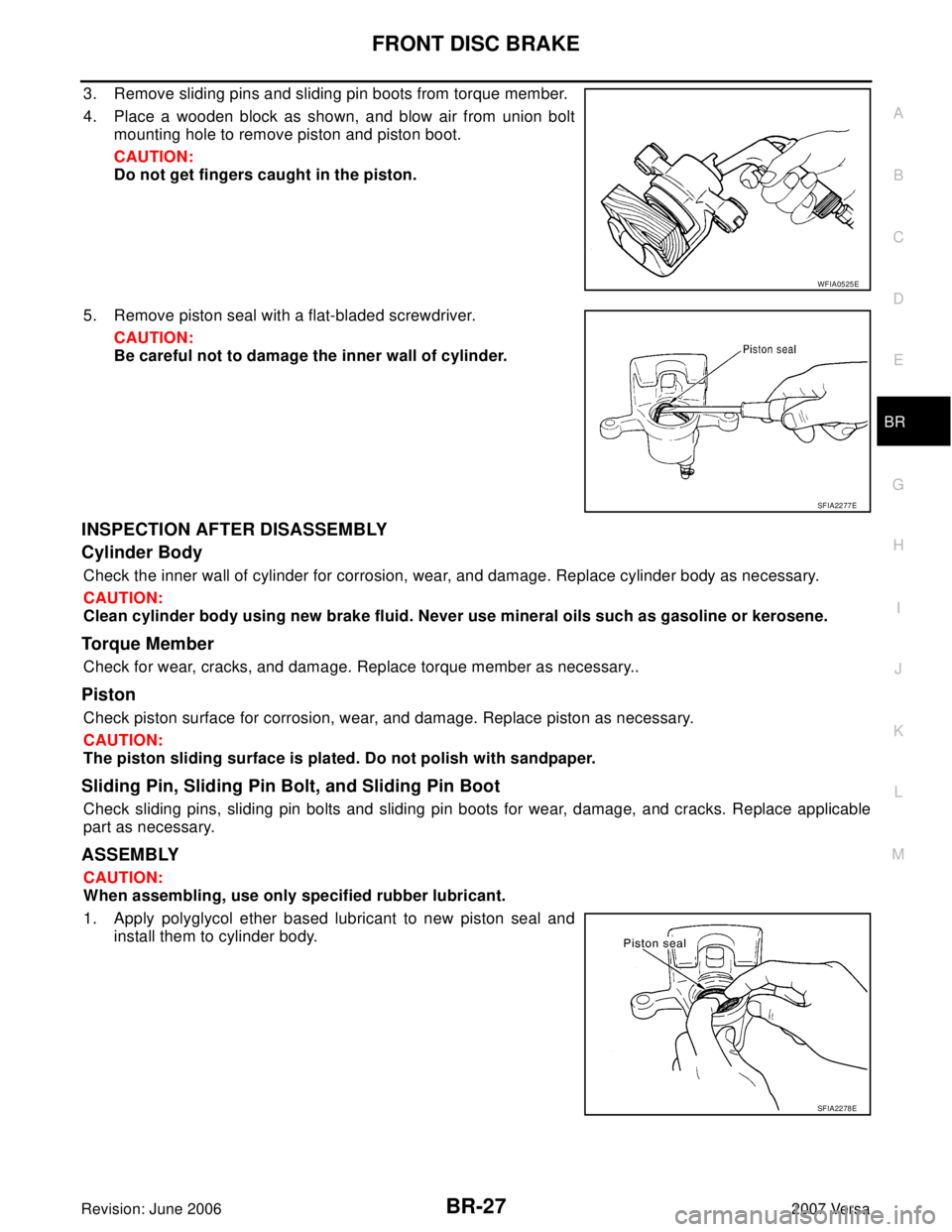
3. Remove sliding pins and sliding pin boots from torque member.
4. Place a wooden block as shown, and blow air from union bolt
mounting hole to remove piston and piston boot.
CAUTION:
Do not get fingers caught in the piston.
5. Remove piston seal with a flat-bladed screwdriver.
CAUTION:
Be careful not to damage the inner wall of cylinder.
INSPECTION AFTER DISASSEMBLY
Cylinder Body
Check the inner wall of cylinder for corrosion, wear, and damage. Replace cylinder body as necessary.
CAUTION:
Clean cylinder body using new brake fluid. Never use mineral oils such as gasoline or kerosene.
Torque Member
Check for wear, cracks, and damage. Replace torque member as necessary..
Piston
Check piston surface for corrosion, wear, and damage. Replace piston as necessary.
CAUTION:
The piston sliding surface is plated. Do not polish with sandpaper.
Sliding Pin, Sliding Pin Bolt, and Sliding Pin Boot
Check sliding pins, sliding pin bolts and sliding pin boots for wear, damage, and cracks. Replace applicable
part as necessary.
ASSEMBLY
CAUTION:
When assembling, use only specified rubber lubricant.
1. Apply polyglycol ether based lubricant to new piston seal and
install them to cylinder body.
WFIA0525E
SFIA2277E
SFIA2278E
Page 859 of 2896
CL-2
PRECAUTIONS
Revision: June 20062007 Versa
PRECAUTIONSPFP:00001
Precautions for Supplemental Restraint System (SRS) “AIR BAG” and “SEAT
BELT PRE-TENSIONER”
ECS00GVW
The Supplemental Restraint System such as “AIR BAG” and “SEAT BELT PRE-TENSIONER”, used along
with a front seat belt, helps to reduce the risk or severity of injury to the driver and front passenger for certain
types of collision. This system includes seat belt switch inputs and dual stage front air bag modules. The SRS
system uses the seat belt switches to determine the front air bag deployment, and may only deploy one front
air bag, depending on the severity of a collision and whether the front occupants are belted or unbelted.
Information necessary to service the system safely is included in the SRS and SB section of this Service Man-
ual.
WAR NIN G:
�To avoid rendering the SRS inoperative, which could increase the risk of personal injury or death
in the event of a collision which would result in air bag inflation, all maintenance must be per-
formed by an authorized NISSAN/INFINITI dealer.
�Improper maintenance, including incorrect removal and installation of the SRS, can lead to per-
sonal injury caused by unintentional activation of the system. For removal of Spiral Cable and Air
Bag Module, see the SRS section.
�Do not use electrical test equipment on any circuit related to the SRS unless instructed to in this
Service Manual. SRS wiring harnesses can be identified by yellow and/or orange harnesses or
harness connectors.
Service Notice or PrecautionsECS00FST
�Use recommended brake fluid when adding fluid to the clutch reservoir tank. Refer to MA-11,
"RECOMMENDED FLUIDS AND LUBRICANTS".
�Never reuse fluid drained from clutch system.
�Be careful not to splash brake fluid on painted areas.
�Use new brake fluid to clean or wash all parts of master cylinder and operating cylinder.
�Never use mineral oils such as gasoline or kerosene. It will ruin the rubber parts of the hydraulic
system.
�If transaxle assembly is removed from the vehicle, always replace CSC (Concentric slave cylin-
der). Return CSC to original position to remove transaxle assembly. Dust on clutch disc sliding
parts may damage CSC seal and may cause clutch fluid leakage.
�Do not disassemble clutch master cylinder and CSC.
WAR NIN G:
After cleaning clutch disc, clean it with a dust collector. Do not use compressed air.