Page 1833 of 2896
EM-24Revision: June 2006
OIL PAN
2007 Versa
OIL PANP F P : 1111 0
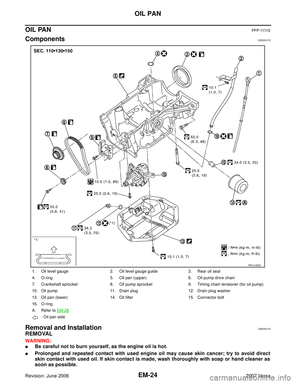
ComponentsEBS00U7G
Removal and InstallationEBS00U7H
REMOVAL
WAR NIN G:
�Be careful not to burn yourself, as the engine oil is hot.
�Prolonged and repeated contact with used engine oil may cause skin cancer; try to avoid direct
skin contact with used oil. If skin contact is made, wash thoroughly with soap or hand cleaner as
soon as possible.
1. Oil level gauge 2. Oil level gauge guide 3. Rear oil seal
4. O-ring 5. Oil pan (upper) 6. Oil pump drive chain
7. Crankshaft sprocket 8. Oil pump sprocket 9. Timing chain tensioner (for oil pump)
10. Oil pump 11. Drain plug 12. Drain plug washer
13. Oil pan (lower) 14. Oil filter 15. Connector bolt
16. O-ring
A. Refer to EM-26
: Oil pan side
PBIC4482E
Page 1834 of 2896

OIL PAN
EM-25
C
D
E
F
G
H
I
J
K
L
MA
EM
Revision: June 20062007 Versa
1. Drain engine oil. Refer to LU-5, "ENGINE OIL" .
2. Remove engine and transaxle assembly. Refer to EM-73
.
3. Remove oil filter using Tool.
CAUTION:
When removing, prepare a shop cloth to absorb any engine oil leakage or spillage.
4. Remove oil pan (lower) bolts in reverse order as shown.
5. After removing the bolts and nuts, separate the mating surface
and remove the sealant using Tool.
CAUTION:
Be careful not to damage the mating surfaces.
6. Remove the following parts:
�Flywheel (M/T models) or drive plate (A/T or CVT models); Refer to EM-77, "CYLINDER BLOCK" .
�Front cover, timing chain, oil pump drive chain; Refer to EM-37, "TIMING CHAIN" .
7. Remove oil pump.
�Loosen bolts in reverse order as shown.
8. Remove oil pan (lower) bolts in reverse order as shown.Tool number : KV10115801 ( — )
: Engine front
PBIC3146J
Tool number : KV10111100 (J-37228)
WBIA0566E
1 : Oil pump
2 : Oil pan (upper)
: Engine front
PBIC3532J
: Engine front
PBIC3533J
Page 1835 of 2896
 and open up a
crack between oil pan (upper) and cylinder block.
CAUTION:
A more adhesive liquid gasket is app")
EM-26Revision: June 2006
OIL PAN
2007 Versa
9. Insert a screwdriver shown by the arrow ( ) and open up a
crack between oil pan (upper) and cylinder block.
CAUTION:
A more adhesive liquid gasket is applied compared to previ-
ous types when shipped, so it should not be forced off the
position not specified.
10. After removing the bolts, separate the mating surface and
remove the sealant using Tool.
�Slide (1) the Tool by tapping (2) its side with a hammer to
remove the lower oil pan from the upper oil pan.
CAUTION:
Be careful not to damage the mating surfaces.
11. Remove O-ring between cylinder block and oil pan (upper).
INSPECTION AFTER REMOVAL
Oil Filter
Clean oil strainer portion (part of the oil pump) if any object attached.
INSTALLATION
1. Use a scraper (A) to remove old liquid gasket from mating sur-
faces.
�Remove the old liquid gasket from mating surface of cylinder
block.
�Remove old liquid gasket from the bolt holes and threads.
CAUTION:
Never scratch or damage the mating surfaces when clean-
ing off old liquid gasket.
: Engine front
PBIC3534J
Tool number : KV10111100 (J-37228)
WBIA0566E
PBIC3949E
Page 1836 of 2896

OIL PAN
EM-27
C
D
E
F
G
H
I
J
K
L
MA
EM
Revision: June 20062007 Versa
2. Apply the sealant without breaks to the specified location using
Tool.
Use Genuine Silicone RTV Sealant or equivalent. Refer to
GI-46, "
Recommended Chemical Products and Sealants" .
CAUTION:
Apply liquid gasket to outside of bolt hole for the positions
shown by marks.
3. Install new O-ring at cylinder block side.
CAUTION:
Install avoiding misalignment of O-ring.
4. Tighten bolts in numerical order as shown.
5. Install rear oil seal with the following procedure.
CAUTION:
�The installation of rear oil seal should be completed within 5 minutes after installing oil pan
(upper).
�Always replace rear oil seal with new one.
�Never touch oil seal lip.
a. Wipe off liquid gasket protruding to the rear oil seal mating part of oil pan (upper) and cylinder block using
a scraper.
b. Apply engine oil to entire outside area of rear oil seal.Tool number WS39930000 ( – )
1 : Oil pan (upper)
A : 2 mm protruded to outside
B : 2 mm protruded to rear oil seal mounting side
: Engine front
: Engine outside
PBIC4587E
: Engine front
PBIC3533J
Page 1837 of 2896
 and inner diameter 90 mm (3.54 in) (A) (commer-
cial service tool).
�Press")
EM-28Revision: June 2006
OIL PAN
2007 Versa
c. Press-fit the rear oil seal using a drift with outer diameter 115
mm (4.53 in) and inner diameter 90 mm (3.54 in) (A) (commer-
cial service tool).
�Press-fit to the specified dimensions as shown.
CAUTION:
�Never touch the grease applied to the oil seal lip.
�Be careful not to damage the rear oil seal mounting part
of oil pan (upper) and cylinder block or the crankshaft.
�Press-fit straight, making sure that rear oil seal does not
curl or tilt.
NOTE:
The standard surface of the dimension is the rear end surface of cylinder block.
6. Install oil pump.
�Tighten bolts in numerical order as shown.
7. Install oil pump sprocket, oil pump drive chain and other related
parts if removed.
8. Use a scraper (A) to remove old liquid gasket from mating sur-
faces.
�Also remove old liquid gasket from mating surface of oil pan
(upper).
�Remove old liquid gasket from the bolt holes and threads.
PBIC3951E
1 : Rear oil seal
A : Cylinder block rear end surface
1 : Oil pump
2 : Oil pan (upper)
: Engine front
PBIC3952E
PBIC3532J
PBIC3953E
Page 1838 of 2896
OIL PAN
EM-29
C
D
E
F
G
H
I
J
K
L
MA
EM
Revision: June 20062007 Versa
9. Apply the sealant without breaks to the specified location using
Tool.
Use Genuine Silicone RTV Sealant or equivalent. Refer to
GI-46, "
Recommended Chemical Products and Sealants" .
10. Tighten bolts in numerical order as shown.
11. Install oil filter with the following procedure:
a. Remove foreign materials adhering to the oil filter installation
surface.
b. Apply new engine oil to the oil seal contact surface of new oil fil-
ter.
c. Screw oil filter manually until it touches the installation surface,
then tighten it by 2/3 turn. Or tighten to specification.
12. Installation of the remaining components is in the reverse order of removal.Tool number WS39930000 ( – )
1 : Oil pan (lower)
: Engine outside
PBIC4590E
: Engine front
PBIC3146J
Oil filter: : 17.7 N·m (1.8 kg-m, 13 ft-lb)
SM A22 9B
Page 1846 of 2896
TIMING CHAIN
EM-37
C
D
E
F
G
H
I
J
K
L
MA
EM
Revision: June 20062007 Versa
TIMING CHAINPFP:13028
ComponentsEBS00U7M
1. Timing chain slack guide 2. Timing chain tensioner 3. Camshaft sprocket (EXH)
4. Timing chain 5. Oil filler cap 6. Front cover
7. O-ring 8.Intake valve timing control solenoid
valve9. Crankshaft pulley bolt
10. Crankshaft pulley 11. Front oil seal 12. Drive belt auto-tensioner
PBIC3538J
Page 1849 of 2896
 shown, and then
remove the front cover.
CAUTION:
�Be careful not to damage the mating surface.
�A more")
EM-40Revision: June 2006
TIMING CHAIN
2007 Versa
13. Cut liquid gasket by prying the position ( ) shown, and then
remove the front cover.
CAUTION:
�Be careful not to damage the mating surface.
�A more adhesive liquid gasket is applied compared to
previous types when shipped, so it should not be forced
off the position not specified.
14. Remove front oil seal from front cover.
�Lift up front oil seal using a suitable tool.
CAUTION:
Be careful not to damage front cover.
15. Push in timing chain tensioner plunger.
16. Insert a stopper pin (A) into the body hole to retain the plunger in
collapsed position.
NOTE:
Use approximately 1.5 mm (0.059 in) diameter. hard metal pin
as a stopper pin.
17. Remove timing chain tensioner (1).
18. Remove timing chain slack guide (2), timing chain tension guide
(3) and timing chain (1).
CAUTION:
Never rotate each crankshaft and camshaft individually
while timing chain is removed. It causes interference
between valve and piston.
PBIC3357J
PBIC3165J
PBIC3166J


4.")