Page 1853 of 2896
 and the timing chain
slack guide (2).
8. Install timing chain tensioner (1).
�Fix the plunger at the most")
EM-44Revision: June 2006
TIMING CHAIN
2007 Versa
7. Install the timing chain tension guide (3) and the timing chain
slack guide (2).
8. Install timing chain tensioner (1).
�Fix the plunger at the most compressed position using a stop-
per pin (A), and then install it.
�Securely pull out the stopper pin after installing the timing
chain tensioner.
9. Check matching mark position of timing chain and each sprocket again.
10. Apply new engine oil to new front oil seal joint surface.
11. Using a suitable tool install front oil seal so that each seal lip is oriented as shown.
�Press-fit front oil seal until it is flush with front end surface of
front cover as shown below with a suitable tool.
CAUTION:
�Be careful not to damage front cover and crankshaft.
�Press-fit oil seal straight to avoid causing burrs or tilting.
�Never touch grease applied onto oil seal lip.
12. Install new O-ring to cylinder block.
1 : Timing chain
PBIC3166J
PBIC3165J
A : Dust seal lip
B: Oil seal lip
: Engine front
: Engine rear
Within 0.3 mm (0.012 in) toward engine front
Within 0.5 mm (0.020 in) toward engine rear
PBIC3485J
Page 1854 of 2896

TIMING CHAIN
EM-45
C
D
E
F
G
H
I
J
K
L
MA
EM
Revision: June 20062007 Versa
CAUTION:
Be sure O-rings a aligned properly.
13. Apply the sealant without breaks to the specified location using
Tool.
Use Genuine Silicone RTV Sealant or equivalent. Refer to
GI-46, "
Recommended Chemical Products and Sealants" .
14. Make sure that matching marks of timing chain and each sprocket are still aligned.
CAUTION:
�Make sure O-ring on cylinder block is correctly installed.
�Be careful not to damage front oil seal by interference with front end of crankshaft.
15. Install front cover, and tighten bolts in numerical order as shown.
CAUTION:
Attaching should be done within 5 minutes after liquid gas-
ket application.
NOTE:
Refer to the following for the installation position of bolts.
16. Tighten all bolts are in two stages to specified torque in numeri-
cal order as shown.
CAUTION:
Be sure to wipe off any excessive liquid gasket leaking.
17. Install crankshaft pulley.
CAUTION:
�Never damage front oil seal lip section.Tool number WS39930000 ( – )
A : Liquid gasket application area
: Engine outside
PBIC3959E
M6 bolts : No. 1
M10 bolts : No. 6, 7, 10, 11, 14
M12 bolts : No. 2, 4, 8, 12
M8 bolts : Except the above
PBIC3164J
Page 1863 of 2896
 (2).
NOTE:
Secure the hexagonal part (A) of camshaft (EXH) using wrench
to tighten bolt.
11. Install timing chain and r")
EM-54Revision: June 2006
CAMSHAFT
2007 Versa
10. Install camshaft sprocket (EXH) (2).
NOTE:
Secure the hexagonal part (A) of camshaft (EXH) using wrench
to tighten bolt.
11. Install timing chain and related parts. Refer to EM-37, "
TIMING CHAIN" .
12. Inspect and adjust valve clearance. Refer to EM-55, "
Valve Clearance" .
13. Installation of the remaining components is in the reverse order of removal.
INSPECTION AFTER INSTALLATION
The following are procedures for checking fluids leak, lubricates leak.
�Before starting engine, check oil/fluid levels including engine coolant and engine oil. If less than required
quantity, fill to the specified level. Refer to GI-46, "
Recommended Chemical Products and Sealants" .
�Use procedure below to check for fuel leakage.
–Turn ignition switch “ON” (with engine stopped). With fuel pressure applied to fuel piping, check for fuel
leakage at connection points.
–Start engine. With engine speed increased, check again for fuel leakage at connection points.
�Run engine to check for unusual noise and vibration.
NOTE:
If hydraulic pressure inside timing chain tensioner drops after removal/installation, slack in the guide may
generate a pounding noise during and just after engine start. However, this is normal. Noise will stop after
hydraulic pressure rises.
�Warm up engine thoroughly to make sure there is no leakage of fuel, or any oil/fluids including engine oil
and engine coolant.
�Bleed air from lines and hoses of applicable lines, such as in cooling system.
�After cooling down engine, again check oil/fluid levels including engine oil and engine coolant. Refill to the
specified level, if necessary.
Summary of the inspection items:
* Transmission/transaxle/CVT fluid, power steering fluid, brake fluid, etc.
Inspection of Camshaft Sprocket (INT) Oil Groove
CAUTION:
�Perform this inspection only when DTC P0011 is detected in self-diagnostic results of CONSULT-II
and it is directed according to inspection procedure of EC section. Refer to EC-47, "
ON BOARD
DIAGNOSTIC (OBD) SYSTEM" .
�Check when engine is cold so as to prevent burns from the splashing engine oil.
1. Check engine oil level. Refer to LU-5, "
ENGINE OIL LEVEL" .
2. Perform the following procedure so as to prevent the engine from being unintentionally started while
checking.
a. Remove intake manifold. Refer to EM-18, "
Components" .
1 : Camshaft sprocket (INT)
Camshaft sprocket
bolt (EXH): 88.2 N·m (9.0 kg-m, 65 ft-lb)
PBIC3454J
Item Before starting engine Engine running After engine stopped
Engine coolant Level Leakage Level
Engine oil Level Leakage Level
Other oils and fluid* Level Leakage Level
Fuel Leakage Leakage Leakage
Exhaust gases — Leakage —
Page 1868 of 2896

OIL SEAL
EM-59
C
D
E
F
G
H
I
J
K
L
MA
EM
Revision: June 20062007 Versa
OIL SEALPFP:12279
Removal and Installation of Valve Oil SealEBS00T6H
REMOVAL
1. Remove camshafts. Refer to EM-47, "Components" .
2. Remove valve lifters. Refer to EM-47, "
CAMSHAFT" .
3. Rotate crankshaft, and set piston whose valve oil seal is to be removed to TDC. This will prevent valve
from dropping into cylinder.
CAUTION:
When rotating crankshaft, be careful to avoid scarring front cover with timing chain.
4. Remove valve collet.
�Compress valve spring using Tool, the attachment and the
adapter (A). Remove valve collet with a suitable magnet hand
(B).
CAUTION:
When working, be careful not to damage valve lifter holes.
5. Remove valve spring retainer, valve spring and valve spring seat.
6. Remove valve oil seal using Tool (A).
INSTALLATION
1. Apply new engine oil to valve oil seal joint surface and seal lip.
2. Press in valve oil seal to the height “H” shown using Tool (A).
3. Installation of the remaining components is in the reverse order of removal.Tool number : KV101092S0 (J-26336-B)
PBIC3727E
Tool number :KV10107902 (J-38959)
PBIC3728E
Height “H” : 15.1 - 15.7 mm (0.594 - 0.618 in)
Tool number : KV10115600 ( — )
PBIC3 211 J
Page 1869 of 2896
; Refer to EI-22, \"FENDER PROTECTOR\"")
EM-60Revision: June 2006
OIL SEAL
2007 Versa
Removal and Installation of Front Oil SealEBS00T6I
REMOVAL
1. Remove the following parts.
�Front fender protector (RH); Refer to EI-22, "FENDER PROTECTOR" .
�Drive belt; Refer to EM-13, "Components" .
�Crankshaft pulley; Refer to EM-37, "Components" .
2. Remove front oil seal using a suitable tool.
CAUTION:
Be careful not to damage front cover and crankshaft.
INSTALLATION
1. Apply new engine oil to new front oil seal joint surface and seal lip.
2. Install front oil seal so that each seal lip is oriented as shown in
the figure.
�Install front oil seal (2) using a suitable tool with outer diame-
ter 57 mm (2.24 in) and inner diameter 45 mm (1.77 in) (A) to
the dimension as shown.
CAUTION:
�Be careful not to damage front cover and crankshaft.
�Press-fit oil seal straight to avoid causing burrs or tilt-
ing.
�Do not touch grease applied on oil seal lip.
3. Installation of the remaining components is in the reverse order of removal.
A : Dust seal lip
B: Oil seal lip
: Engine outside
: Engine inside
PBIC3485J
Within 0.3 mm (0.012 in) toward engine front
Within 0.5 mm (0.020 in) toward engine rear
PBIC3729E
Page 1870 of 2896

OIL SEAL
EM-61
C
D
E
F
G
H
I
J
K
L
MA
EM
Revision: June 20062007 Versa
Removal and Installation of Rear Oil SealEBS00T6J
REMOVAL
1. Remove transaxle assembly. Refer to MT-15, "TRANSAXLE ASSEMBLY" (M/T models), AT-253, "TRAN-
SAXLE ASSEMBLY" (A/T models) or CVT-207, "TRANSAXLE ASSEMBLY" (CVT models).
2. Remove clutch cover and clutch disk (M/T models). Refer to CL-13, "
CLUTCH DISC, CLUTCH COVER
AND FLYWHEEL" .
3. Remove drive plate (A/T or CVT models) or flywheel (M/T models). Refer to EM-77, "
Components" .
4. Remove rear oil seal with a suitable tool.
CAUTION:
Be careful not to damage crankshaft and cylinder block.
INSTALLATION
1. Apply the liquid gasket lightly to entire outside area of new rear oil seal.
Use Genuine Silicone RTV Sealant or equivalent. Refer to GI-46, "
Recommended Chemical Prod-
ucts and Sealants" .
2. Install rear oil seal so that each seal lip is oriented as shown.
�Install rear oil seal with a suitable tool with an outer diameter
115 mm (4.53 in) and inner diameter 90 mm (3.54 in) (A).
CAUTION:
�Be careful not to damage crankshaft and cylinder
block.
�Press-fit oil seal straight to avoid causing burrs or tilt-
ing.
�Do not touch grease applied onto oil seal lip.
�Install rear oil seal (1) to the position as shown.
NOTE:
The standard surface of the dimension is the rear end surface of
cylinder block.
3. Installation of the remaining components is in the reverse order of removal.
A : Dust seal lip
B : Oil seal lip
: Engine outside
: Engine inside
PBIC3485J
PBIC3951E
A : Rear end surface of cylinder block
PBIC3761E
Page 1873 of 2896

EM-64Revision: June 2006
CYLINDER HEAD
2007 Versa
�Water outlet; Refer to CO-20, "WATER OUTLET AND WATER CONTROL VALVE" .
�Rocker cover; Refer to EM-30, "IGNITION COIL, SPARK PLUG AND ROCKER COVER" .
�Front cover, timing chain; Refer to EM-37, "TIMING CHAIN" .
�Camshaft; Refer to EM-47, "CAMSHAFT" .
6. Remove cylinder head.
�Loosen bolts in reverse order as shown.
�Using TORX socket (size E18), loosen cylinder head bolts.
7. Remove cylinder head gasket.
INSPECTION AFTER REMOVAL
Cylinder Head Bolts Outer Diameter
�Cylinder head bolts are tightened by plastic zone tightening
method. Whenever the size difference between “d1” and “d2”
exceeds the limit, replace them with a new one.
�If reduction of outer diameter appears in a position other than
“d2”, use it as “d2” point.
Cylinder Head Distortion
NOTE:
When performing this inspection, cylinder block distortion should be also checked. Refer to EM-98, "
CYLIN-
DER BLOCK TOP SURFACE DISTORTION" .
1. Wipe off engine oil and remove water scale (like deposit), gasket, sealant, carbon, etc. with a scraper.
CAUTION:
Use utmost care not to allow gasket debris to enter passages for engine oil or water.
2. At each of several locations on bottom surface of cylinder head,
measure the distortion in six directions using straightedge (A)
and feeler gauge (B).
�If it exceeds the limit, replace cylinder head.
: Engine front
PBIC3206J
Limit (“d1” – “d2”): 0.15 mm (0.0059 in)
PBIC3994E
Limit: 0.1 mm (0.004 in)
PBIC3207J
Page 1875 of 2896
EM-66Revision: June 2006
CYLINDER HEAD
2007 Versa
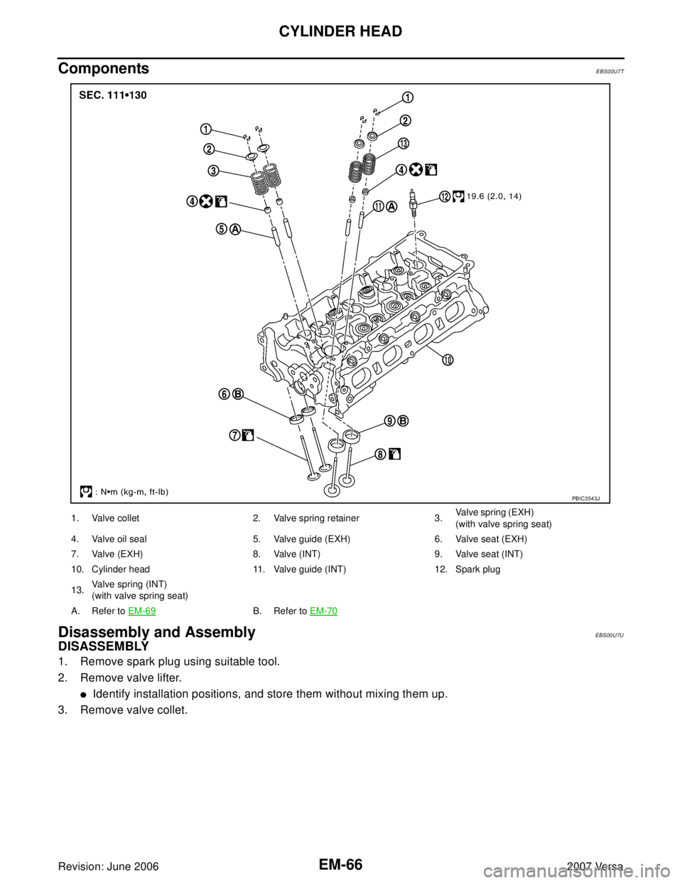
ComponentsEBS00U7T
Disassembly and AssemblyEBS00U7U
DISASSEMBLY
1. Remove spark plug using suitable tool.
2. Remove valve lifter.
�Identify installation positions, and store them without mixing them up.
3. Remove valve collet.
1. Valve collet 2. Valve spring retainer 3.Va l ve sp r in g ( E XH )
(with valve spring seat)
4. Valve oil seal 5. Valve guide (EXH) 6. Valve seat (EXH)
7. Valve (EXH) 8. Valve (INT) 9. Valve seat (INT)
10. Cylinder head 11. Valve guide (INT) 12. Spark plug
13.Va l v e s p r i n g (I N T )
(with valve spring seat)
A. Refer to EM-69
B. Refer to EM-70
PBIC3543J