Page 258 of 2896

ON-VEHICLE SERVICE
AT-245
D
E
F
G
H
I
J
K
L
MA
B
AT
Revision: June 20062007 Versa
Inspection
�Inspect the sliding surfaces of each accumulator piston and
transaxle case, and replace if damaged or dented.
(1): Servo release accumulator piston
(2): N-D accumulator piston
�Inspect the sliding surfaces of manual valve and valve body, and
replace if damaged or dented.
�Inspect each return spring, and replace if damaged, deformed or
worn. Refer to AT-380, "
Accumulator" for free length (L1 ) and
length (L
2 ).
(1): Return spring (Servo release accumulator)
(2): Return spring (N-D accumulator)
CAUTION:
Do not remove spring retainer (3).
Installation
Installation is in the reverse order of removal.
CAUTION:
�Completely remove all moisture, oil and old gasket from the oil pan gasket mounting surface of
transaxle case and oil pan.
�Do not reuse O-rings, lip seals, oil pan gasket and oil pan bolts.
�Apply ATF to manual valve, O-rings, lip seals and sliding surfaces of the transaxle case.
NOTE:
�Set manual shaft in “N” position, then align manual plate (1) with
groove in manual valve (2).
�After installing control valve assembly to transaxle case, make
sure that selector lever can be moved to all positions.
�After completing installation, check for A/T fluid leakage and A/T
fluid level. Refer to AT- 1 6 , "
Checking A/T Fluid" .
WCIA0652E
SCIA6955E
SCIA7090E
Page 263 of 2896
AT-250
ON-VEHICLE SERVICE
Revision: June 20062007 Versa
Differential Side Oil SealUCS005VV
COMPONENTS
REMOVAL AND INSTALLATION
Removal
1. Remove front drive shaft. Refer to EI-22, "Removal and Installation" .
2. Remove differential side oil seals using a flat-bladed screw-
driver.
CAUTION:
Be careful not to scratch transaxle case and converter
housing.
1. A/T 2. LH differential side oil seal 3. RH differential side oil seal
SCIA8021E
SCIA4857E
Page 264 of 2896
ON-VEHICLE SERVICE
AT-251
D
E
F
G
H
I
J
K
L
MA
B
AT
Revision: June 20062007 Versa
Installation
Installation is in the reverse order of removal.
NOTE:
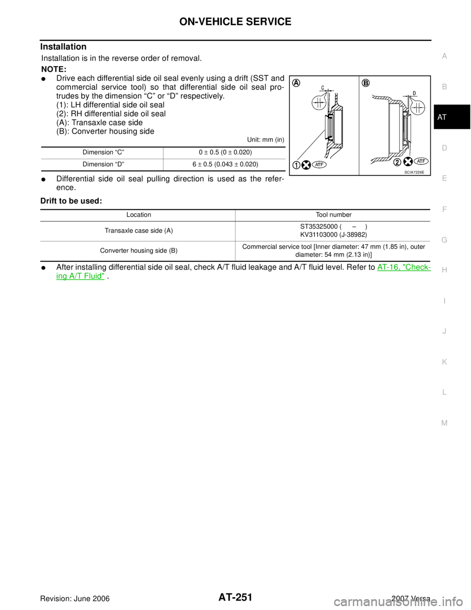
�Drive each differential side oil seal evenly using a drift (SST and
commercial service tool) so that differential side oil seal pro-
trudes by the dimension “C” or “D” respectively.
(1): LH differential side oil seal
(2): RH differential side oil seal
(A): Transaxle case side
(B): Converter housing side
Unit: mm (in)
�Differential side oil seal pulling direction is used as the refer-
ence.
Drift to be used:
�After installing differential side oil seal, check A/T fluid leakage and A/T fluid level. Refer to AT- 1 6 , "Check-
ing A/T Fluid" .
Dimension “C” 0 ± 0.5 (0 ± 0.020)
Dimension “D” 6 ± 0.5 (0.043 ± 0.020)
SCIA7226E
Location Tool number
Transaxle case side (A)ST35325000 ( – )
KV31103000 (J-38982)
Converter housing side (B)Commercial service tool [Inner diameter: 47 mm (1.85 in), outer
diameter: 54 mm (2.13 in)]
Page 271 of 2896
AT-258
OVERHAUL
Revision: June 20062007 Versa
1. Pinion mate gear thrust washer 2. Pinion mate gear 3. Pinion mate shaft
4. Lock pin 5. Side gear 6. Side gear thrust washer
7. Differential side bearing 8. Speedometer drive gear 9. Differential case
10. Final gear 11. Differential side bearing adjusting
shim12. Plug
13. O-ring 14. Bracket 15. RH differential side oil seal
16. Torque converter 17. Converter housing 18. Differential lubricant tube
19. Clip 20. O-ring 21. O-ring
22. Oil pump housing oil seal 23. Oil pump housing 24. Outer gear
25. Inner gear 26. Oil pump cover 27. Seal ring
28. Oil pump assembly
Refer to GI section to make sure icons (symbol marks) in the figure. Refer to GI-10, "
Components" .
Page 273 of 2896
AT-260
OVERHAUL
Revision: June 20062007 Versa
7. Differential side bearing 8. Speedometer drive gear 9. Differential case
10. Final gear 11. Differential side bearing adjusting
shim12. Speedometer pinion
13. O-ring 14. Bracket 15. RH differential side oil seal
16. Torque converter 17. Converter housing 18. Differential lubricant tube
19. Clip 20. O-ring 21. O-ring
22. Oil pump housing oil seal 23. Oil pump housing 24. Outer gear
25. Inner gear 26. Oil pump cover 27. Seal ring
28. Oil pump assembly
Refer to GI section to make sure icons (symbol marks) in the figure. Refer to GI-10, "
Components" .
Page 277 of 2896

AT-264
OVERHAUL
Revision: June 20062007 Versa
10. Snap ring 11. Radial needle bearing 12. Seal ring
13. Bearing retainer 14. O-ring 15. Servo release accumulator piston
16. Return spring 17. Control valve assembly 18. Oil pan gasket
19. Oil pan 20. Drain plug gasket 21. Drain plug
22. Magnet 23. Oil pan fitting bolt 24. Snap ring
25. O-ring 26. O-ring 27. N-D accumulator piston
28. Return spring 29. O-ring 30. Lip seal
31. Turbine revolution sensor (power
train revolution sensor)32. O-ring 33. Retaining pin
34. Detent spring 35. Retaining pin 36. Manual shaft
37. Manual shaft oil seal 38. Manual plate 39. Parking rod plate
40. Parking rod 41. OD servo piston retainer 42. Snap ring
43. O-ring 44. OD servo piston 45. D-ring
46. Servo piston retainer 47. O-ring 48. E-ring
49. Spring retainer 50. OD servo return spring 51. D-ring
52. Band servo piston 53. Band servo thrust washer 54. Band servo piston stem
55. 2nd servo return spring 56. PNP switch 57. Parking shaft
58. Return spring 59. Thrust needle bearing 60. Seal ring
61. Output shaft 62. Output shaft bearing 63. Output shaft adjusting shim
64. Side cover 65. Side cover fitting bolt 66. Lock nut
67. Idler gear 68. Idler gear bearing 69. Reduction pinion gear adjusting
shim
70. Parking actuator support 71. Parking pawl 72. LH differential side oil seal
73. Revolution sensor
Refer to GI section to make sure icons (symbol marks) in the figure. Refer to GI-10, "
Components" .
However, refer to the following symbol for others.
: Apply Genuine Anaerobic Liquid Gasket or equivalent.
Page 287 of 2896
AT-274
DISASSEMBLY
Revision: June 20062007 Versa
27. Remove RH differential side oil seal from converter housing
using a flat-bladed screwdriver.
CAUTION:
Be careful not to scratch converter housing.
28. Remove differential lubricant tube (1) and clips (2) from con-
verter housing.
: Bolt (3)
29. Remove oil pump assembly according to the following procedures.
a. Remove O-ring from input shaft assembly (high clutch drum).
b. Remove oil pump assembly fitting bolts, and then remove oil
pump assembly (1) from transaxle case.
c. Remove O-ring from oil pump assembly (1).
SCIA3283E
SCIA7817E
SCIA5634E
SCIA6036J
Page 297 of 2896
AT-284
DISASSEMBLY
Revision: June 20062007 Versa
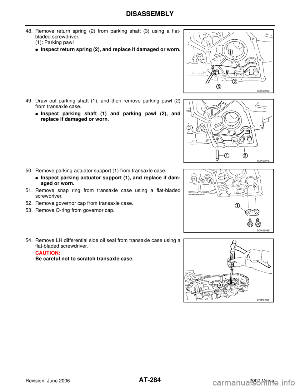
48. Remove return spring (2) from parking shaft (3) using a flat-
bladed screwdriver.
(1): Parking pawl
�Inspect return spring (2), and replace if damaged or worn.
49. Draw out parking shaft (1), and then remove parking pawl (2)
from transaxle case.
�Inspect parking shaft (1) and parking pawl (2), and
replace if damaged or worn.
50. Remove parking actuator support (1) from transaxle case.
�Inspect parking actuator support (1), and replace if dam-
aged or worn.
51. Remove snap ring from transaxle case using a flat-bladed
screwdriver.
52. Remove governor cap from transaxle case.
53. Remove O-ring from governor cap.
54. Remove LH differential side oil seal from transaxle case using a
flat-bladed screwdriver.
CAUTION:
Be careful not to scratch transaxle case.
SCIA6996E
SCIA6997E
SCIA6998E
ATM0076D