Page 298 of 2896
REPAIR FOR COMPONENT PARTS
AT-285
D
E
F
G
H
I
J
K
L
MA
B
AT
Revision: June 20062007 Versa
REPAIR FOR COMPONENT PARTSPFP:00000
Manual ShaftUCS005W 3
COMPONENTS
REMOVAL
1. Remove detent spring from transaxle case.
2. Drive out retaining pin of manual plate using the pin punch.
1. Manual shaft oil seal 2. Parking rod 3. Retaining pin
4. Parking rod plate 5. Retaining pin 6. Manual plate
7. Manual shaft 8. Detent spring 9. Retaining pin
Refer to GI section to make sure icons (symbol marks) in the figure. Refer to GI-10, "
Components" .
SCIA5907J
SAT3 1 3G
SCIA5381E
Page 299 of 2896
AT-286
REPAIR FOR COMPONENT PARTS
Revision: June 20062007 Versa
3. Pull out retaining pin (2) of parking rod plate (1) using nippers.
4. Pull out retaining pin (1) of manual shaft using nippers.
5. Remove parking rod plate (with parking rod) (3) from manual
shaft (1).
6. Remove parking rod from parking rod plate (3).
7. Remove manual plate (2) from manual shaft (1).
8. Draw out manual shaft (1) from transaxle case.
9. Remove manual shaft oil seal from transaxle case using a flat-
bladed screwdriver.
CAUTION:
Be careful not to scratch transaxle case.
INSPECTION
Check component parts, and replace if damaged or worn.
SCIA5806J
SCIA6514J
SCIA7005E
SAT0 8 0D
Page 300 of 2896

REPAIR FOR COMPONENT PARTS
AT-287
D
E
F
G
H
I
J
K
L
MA
B
AT
Revision: June 20062007 Versa
INSTALLATION
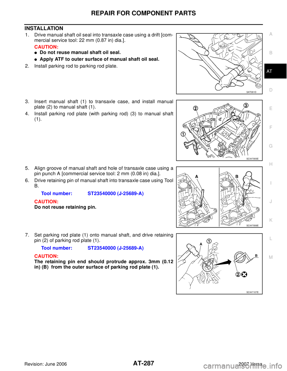
1. Drive manual shaft oil seal into transaxle case using a drift [com-
mercial service tool: 22 mm (0.87 in) dia.].
CAUTION:
�Do not reuse manual shaft oil seal.
�Apply ATF to outer surface of manual shaft oil seal.
2. Install parking rod to parking rod plate.
3. Insert manual shaft (1) to transaxle case, and install manual
plate (2) to manual shaft (1).
4. Install parking rod plate (with parking rod) (3) to manual shaft
(1).
5. Align groove of manual shaft and hole of transaxle case using a
pin punch A [commercial service tool: 2 mm (0.08 in) dia.].
6. Drive retaining pin of manual shaft into transaxle case using Tool
B.
CAUTION:
Do not reuse retaining pin.
7. Set parking rod plate (1) onto manual shaft, and drive retaining
pin (2) of parking rod plate (1).
CAUTION:
The retaining pin end should protrude approx. 3mm (0.12
in) (B) from the outer surface of parking rod plate (1).
SAT0 8 1D
SCIA7005E
Tool number: ST23540000 (J-25689-A)
SCIA7006E
Tool number: ST23540000 (J-25689-A)
SCIA7107E
Page 302 of 2896
REPAIR FOR COMPONENT PARTS
AT-289
D
E
F
G
H
I
J
K
L
MA
B
AT
Revision: June 20062007 Versa
Oil PumpUCS005W 4
COMPONENTS
DISASSEMBLY
1. Remove seal rings (1) from oil pump assembly (2).
2. Remove bolts in the order as shown in the figure, and remove oil
pump cover.
1. Oil pump housing oil seal 2. Oil pump housing 3. Outer gear
4. Inner gear 5. Oil pump cover 6. Seal ring
Refer to GI section to make sure icons (symbol marks) in the figure. Refer to GI-10, "
Components" .
SCIA5908J
SCIA7016E
SAT0 9 1D
Page 303 of 2896
AT-290
REPAIR FOR COMPONENT PARTS
Revision: June 20062007 Versa
3. Remove inner gear and outer gear from oil pump housing.
4. Remove oil pump housing oil seal using a flat-bladed screw-
driver.
CAUTION:
Be careful not to scratch oil pump housing.
SAT0 9 2D
SCIA2840E
Page 304 of 2896

REPAIR FOR COMPONENT PARTS
AT-291
D
E
F
G
H
I
J
K
L
MA
B
AT
Revision: June 20062007 Versa
INSPECTION
Oil Pump Housing, Oil Pump Cover, Inner Gear and Outer Gear
Check for wear or damage. Replace if necessary.
Side Clearances
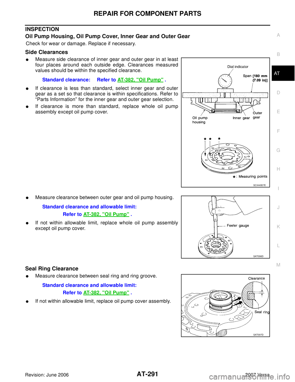
�Measure side clearance of inner gear and outer gear in at least
four places around each outside edge. Clearances measured
values should be within the specified clearance.
�If clearance is less than standard, select inner gear and outer
gear as a set so that clearance is within specifications. Refer to
“Parts Information” for the inner gear and outer gear selection.
�If clearance is more than standard, replace whole oil pump
assembly except oil pump cover.
�Measure clearance between outer gear and oil pump housing.
�If not within allowable limit, replace whole oil pump assembly
except oil pump cover.
Seal Ring Clearance
�Measure clearance between seal ring and ring groove.
�If not within allowable limit, replace oil pump cover assembly.Standard clearance: Refer to AT- 3 8 2 , "
Oil Pump" .
SCIA4957E
Standard clearance and allowable limit:
Refer to AT-382, "
Oil Pump" .
SAT0 9 6D
Standard clearance and allowable limit:
Refer to AT-382, "
Oil Pump" .
SAT0 9 7D
Page 305 of 2896

AT-292
REPAIR FOR COMPONENT PARTS
Revision: June 20062007 Versa
ASSEMBLY
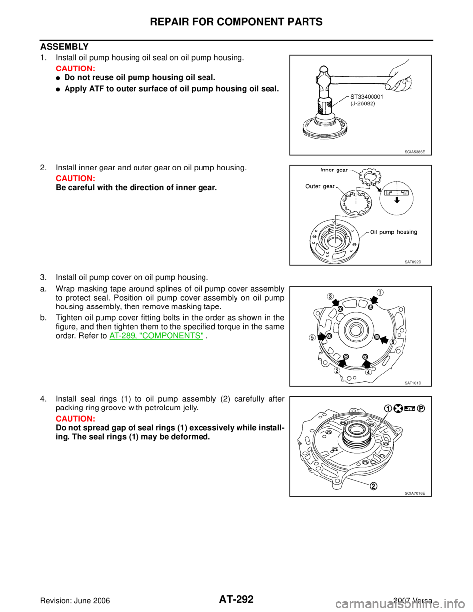
1. Install oil pump housing oil seal on oil pump housing.
CAUTION:
�Do not reuse oil pump housing oil seal.
�Apply ATF to outer surface of oil pump housing oil seal.
2. Install inner gear and outer gear on oil pump housing.
CAUTION:
Be careful with the direction of inner gear.
3. Install oil pump cover on oil pump housing.
a. Wrap masking tape around splines of oil pump cover assembly
to protect seal. Position oil pump cover assembly on oil pump
housing assembly, then remove masking tape.
b. Tighten oil pump cover fitting bolts in the order as shown in the
figure, and then tighten them to the specified torque in the same
order. Refer to AT-289, "
COMPONENTS" .
4. Install seal rings (1) to oil pump assembly (2) carefully after
packing ring groove with petroleum jelly.
CAUTION:
Do not spread gap of seal rings (1) excessively while install-
ing. The seal rings (1) may be deformed.
SCIA5386E
SAT0 9 2D
SAT1 0 1D
SCIA7016E
Page 322 of 2896

REPAIR FOR COMPONENT PARTS
AT-309
D
E
F
G
H
I
J
K
L
MA
B
AT
Revision: June 20062007 Versa
Reverse ClutchUCS005W 8
COMPONENTS
DISASSEMBLY
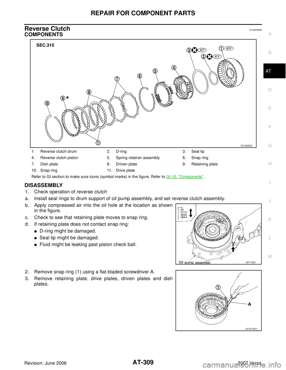
1. Check operation of reverse clutch
a. Install seal rings to drum support of oil pump assembly, and set reverse clutch assembly.
b. Apply compressed air into the oil hole at the location as shown
in the figure.
c. Check to see that retaining plate moves to snap ring.
d. If retaining plate does not contact snap ring:
�D-ring might be damaged.
�Seal lip might be damaged.
�Fluid might be leaking past piston check ball.
2. Remove snap ring (1) using a flat-bladed screwdriver A.
3. Remove retaining plate, drive plates, driven plates and dish
plates.
1. Reverse clutch drum 2. D-ring 3. Seal lip
4. Reverse clutch piston 5. Spring retainer assembly 6. Snap ring
7. Dish plate 8. Driven plate 9. Retaining plate
10. Snap ring 11. Drive plate
Refer to GI section to make sure icons (symbol marks) in the figure. Refer to GI-10, "
Components" .
SCIA6939J
SAT1 5 5D
SCIA7024J