Page 612 of 2896
INTELLIGENT KEY SYSTEM
BL-123
C
D
E
F
G
H
J
K
L
MA
B
BL
Revision: June 20062007 Versa
Power Supply and Ground Circuit CheckEIS0092A
1. CHECK POWER SUPPLY CIRCUIT
1. Turn ignition switch OFF.
2. Disconnect Intelligent Key unit connector.
3. Check voltage between Intelligent Key unit harness connector and ground.
OK or NG
OK >> GO TO 2.
NG >> Repair or replace Intelligent Key power supply circuit.
2. CHECK GROUND CIRCUIT
Check continuity between Intelligent Key unit harness connector and ground.
OK or NG
OK >> Power supply and ground circuits are OK.
NG >> Repair or replace the Intelligent Key unit ground circuit.
Te r m i n a l s
Voltage (V)
(Approx.) (+)
(–)
Intelligent Key unit
connectorTe r m i n a l
M52 11 Ground Battery voltage
PIIB6595E
Intelligent Key unit connector Terminal
GroundContinuity
M52 12 Yes
PIIB6596E
Page 613 of 2896
BL-124
INTELLIGENT KEY SYSTEM
Revision: June 20062007 Versa
Key Switch (Intelligent Key Unit Input) CheckEIS0092B
1. CHECK KEY SWITCH INPUT SIGNAL
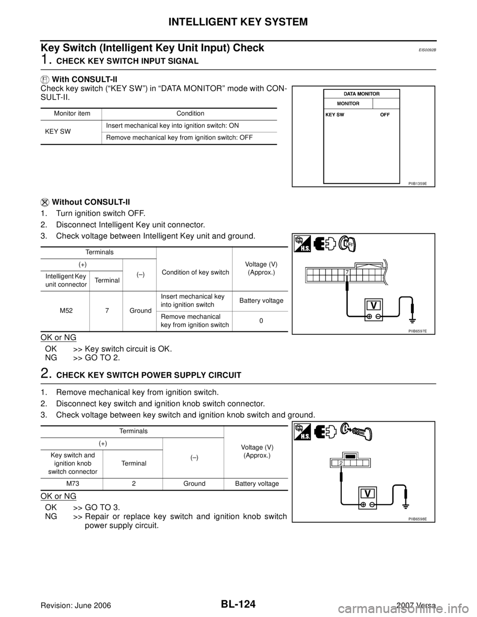
With CONSULT-II
Check key switch (“KEY SW”) in “DATA MONITOR” mode with CON-
SULT-II.
Without CONSULT-II
1. Turn ignition switch OFF.
2. Disconnect Intelligent Key unit connector.
3. Check voltage between Intelligent Key unit and ground.
OK or NG
OK >> Key switch circuit is OK.
NG >> GO TO 2.
2. CHECK KEY SWITCH POWER SUPPLY CIRCUIT
1. Remove mechanical key from ignition switch.
2. Disconnect key switch and ignition knob switch connector.
3. Check voltage between key switch and ignition knob switch and ground.
OK or NG
OK >> GO TO 3.
NG >> Repair or replace key switch and ignition knob switch
power supply circuit.
Monitor item Condition
KEY SWInsert mechanical key into ignition switch: ON
Remove mechanical key from ignition switch: OFF
PIIB1359E
Te r m i n a l s
Condition of key switchVoltage (V)
(Approx.) (+)
(–)
Intelligent Key
unit connectorTerminal
M52 7 GroundInsert mechanical key
into ignition switchBattery voltage
Remove mechanical
key from ignition switch0
PIIB6597E
Te r m i n a l s
Voltage (V)
(Approx.) (+)
(–) Key switch and
ignition knob
switch connectorTerminal
M73 2 Ground Battery voltage
PIIB6598E
Page 615 of 2896
BL-126
INTELLIGENT KEY SYSTEM
Revision: June 20062007 Versa
Key Switch (BCM Input) CheckEIS0092C
1. CHECK KEY SWITCH POWER SUPPLY CIRCUIT
1. Remove mechanical key from ignition switch.
2. Disconnect key switch and ignition knob switch connector.
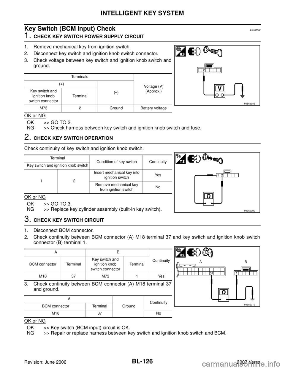
3. Check voltage between key switch and ignition knob switch and
ground.
OK or NG
OK >> GO TO 2.
NG >> Check harness between key switch and ignition knob switch and fuse.
2. CHECK KEY SWITCH OPERATION
Check continuity of key switch and ignition knob switch.
OK or NG
OK >> GO TO 3.
NG >> Replace key cylinder assembly (built-in key switch).
3. CHECK KEY SWITCH CIRCUIT
1. Disconnect BCM connector.
2. Check continuity between BCM connector (A) M18 terminal 37 and key switch and ignition knob switch
connector (B) terminal 1.
3. Check continuity between BCM connector (A) M18 terminal 37
and ground.
OK or NG
OK >> Key switch (BCM input) circuit is OK.
NG >> Repair or replace harness between key switch and ignition knob switch and BCM.
Te r m i n a l s
Voltage (V)
(Approx.) (+)
(–) Key switch and
ignition knob
switch connectorTerminal
M73 2 Ground Battery voltage
PIIB6598E
Te r m i n a l
Condition of key switch Continuity
Key switch and ignition knob switch
12Insert mechanical key into
ignition switchYe s
Remove mechanical key
from ignition switchNo
PIIB6599E
AB
Continuity
BCM connector TerminalKey switch and
ignition knob
switch connectorTe r m i n a l
M18 37 M73 1 Yes
A
GroundContinuity
BCM connector Terminal
M18 37 No
PIIB6601E
Page 616 of 2896
INTELLIGENT KEY SYSTEM
BL-127
C
D
E
F
G
H
J
K
L
MA
B
BL
Revision: June 20062007 Versa
Ignition Knob Switch CheckEIS0092D
1. CHECK IGNITION KNOB SWITCH INPUT SIGNAL
With CONSULT-II
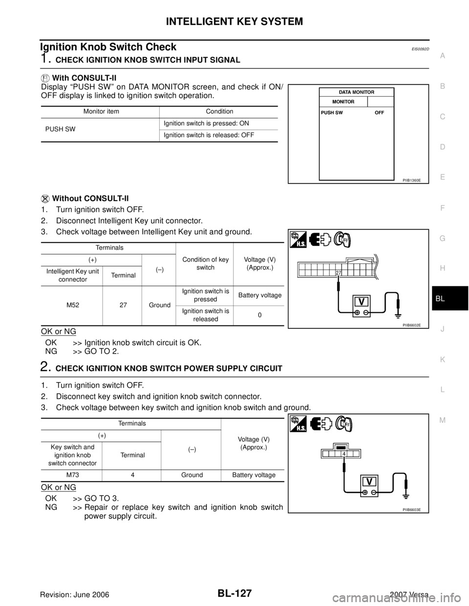
Display “PUSH SW” on DATA MONITOR screen, and check if ON/
OFF display is linked to ignition switch operation.
Without CONSULT-II
1. Turn ignition switch OFF.
2. Disconnect Intelligent Key unit connector.
3. Check voltage between Intelligent Key unit and ground.
OK or NG
OK >> Ignition knob switch circuit is OK.
NG >> GO TO 2.
2. CHECK IGNITION KNOB SWITCH POWER SUPPLY CIRCUIT
1. Turn ignition switch OFF.
2. Disconnect key switch and ignition knob switch connector.
3. Check voltage between key switch and ignition knob switch and ground.
OK or NG
OK >> GO TO 3.
NG >> Repair or replace key switch and ignition knob switch
power supply circuit.
Monitor item Condition
PUSH SWIgnition switch is pressed: ON
Ignition switch is released: OFF
PIIB1360E
Te r m i n a l s
Condition of key
switchVoltage (V)
(Approx.) (+)
(–)
Intelligent Key unit
connectorTe r m i n a l
M52 27 GroundIgnition switch is
pressedBattery voltage
Ignition switch is
released0
PIIB6602E
Te r m i n a l s
Voltage (V)
(Approx.) (+)
(–) Key switch and
ignition knob
switch connectorTe r m i n a l
M73 4 Ground Battery voltage
PIIB6603E
Page 618 of 2896
INTELLIGENT KEY SYSTEM
BL-129
C
D
E
F
G
H
J
K
L
MA
B
BL
Revision: June 20062007 Versa
Door Switch CheckEIS0092E
1. CHECK DOOR SWITCHES INPUT SIGNAL
With CONSULT-II
Check door switches ("DOOR SW-DR", "DOOR SW-AS", "DOOR SW-RL", "DOOR SW-RR", "BACK DOOR
SW") in DATA MONITOR mode with CONSULT–II. Refer to BL-37, "
DATA MONITOR" .
�When doors are open:
�When doors are closed:
Without CONSULT-II
Check voltage between BCM connector M18 or M19 terminals 12, 13, 43, 47, 48 and ground.
OK or NG
OK >> Door switch circuit is OK.
NG >> GO TO 2.DOOR SW-DR : ON
DOOR SW-AS : ON
DOOR SW-RL : ON
DOOR SW-RR : ON
BACK DOOR SW : ON
DOOR SW-DR : OFF
DOOR SW-AS : OFF
DOOR SW-RL : OFF
DOOR SW-RR : OFF
BACK DOOR SW : OFF
LIIA0665E
Connector ItemTerminals
ConditionVoltage (V)
(Approx.)
( + ) ( – )
M18Front door
switch RH12
GroundOpen
↓
Closed0
↓
Battery voltage Rear door
switch RH13
M19Back door
switch43
Front door
switch LH47
Rear door
switch LH48
LIIA1041E
Page 627 of 2896
BL-138
INTELLIGENT KEY SYSTEM
Revision: June 20062007 Versa
Intelligent Key Warning Buzzer (Driver Door) CheckEIS0092K
1. CHECK INTELLIGENT KEY WARNING BUZZER POWER SUPPLY CIRCUIT
1. Disconnect Intelligent Key warning buzzer connector.
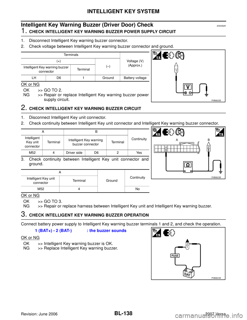
2. Check voltage between Intelligent Key warning buzzer connector and ground.
OK or NG
OK >> GO TO 2.
NG >> Repair or replace Intelligent Key warning buzzer power
supply circuit.
2. CHECK INTELLIGENT KEY WARNING BUZZER CIRCUIT
1. Disconnect Intelligent Key unit connector.
2. Check continuity between Intelligent Key unit connector and Intelligent Key warning buzzer connector.
3. Check continuity between Intelligent Key unit connector and
ground.
OK or NG
OK >> GO TO 3.
NG >> Repair or replace harness between Intelligent Key unit and Intelligent Key warning buzzer.
3. CHECK INTELLIGENT KEY WARNING BUZZER OPERATION
Connect battery power supply to Intelligent Key warning buzzer terminals 1 and 2, and check the operation.
OK or NG
OK >> Intelligent Key warning buzzer is OK.
NG >> Replace Intelligent Key warning buzzer.
Terminals
Voltage (V)
(Approx.) (+)
(–)
Intelligent Key warning buzzer
connectorTe r m i n a l
LH D6 1 Ground Battery voltage
PIIB6622E
AB
Continuity Intelligent
Key unit
connectorTerminalIntelligent Key warning
buzzer connectorTe r m i n a l
M52 4 Driver side D6 2 Yes
A
GroundContinuity
Intelligent Key unit
connectorTe r m i n a l
M52 4 No
PIIB6623E
1 (BAT+) - 2 (BAT-) : the buzzer sounds
PIIB6624E
Page 633 of 2896
BL-144
INTELLIGENT KEY SYSTEM
Revision: June 20062007 Versa
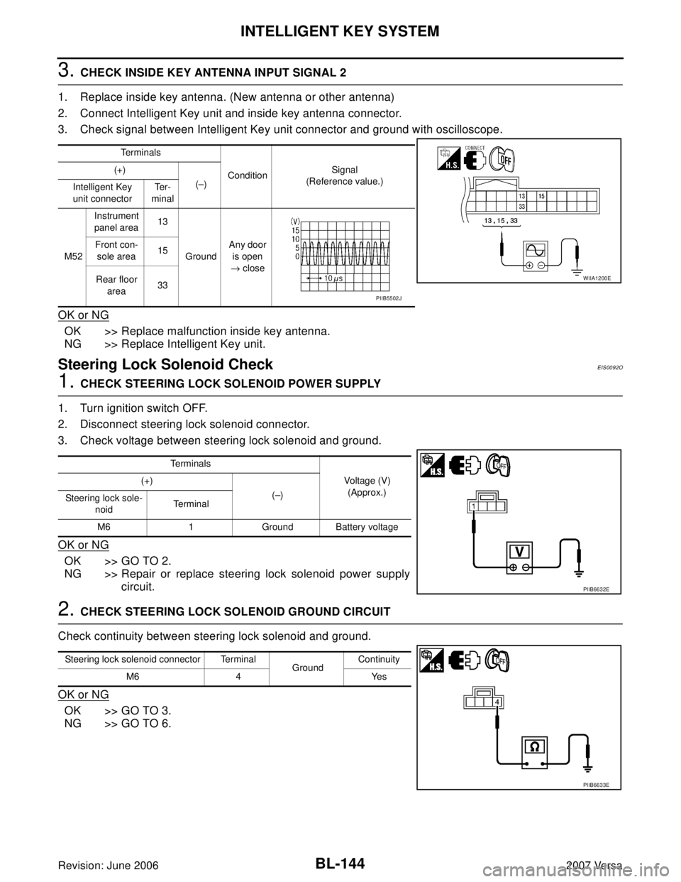
3. CHECK INSIDE KEY ANTENNA INPUT SIGNAL 2
1. Replace inside key antenna. (New antenna or other antenna)
2. Connect Intelligent Key unit and inside key antenna connector.
3. Check signal between Intelligent Key unit connector and ground with oscilloscope.
OK or NG
OK >> Replace malfunction inside key antenna.
NG >> Replace Intelligent Key unit.
Steering Lock Solenoid CheckEIS0092O
1. CHECK STEERING LOCK SOLENOID POWER SUPPLY
1. Turn ignition switch OFF.
2. Disconnect steering lock solenoid connector.
3. Check voltage between steering lock solenoid and ground.
OK or NG
OK >> GO TO 2.
NG >> Repair or replace steering lock solenoid power supply
circuit.
2. CHECK STEERING LOCK SOLENOID GROUND CIRCUIT
Check continuity between steering lock solenoid and ground.
OK or NG
OK >> GO TO 3.
NG >> GO TO 6.
Te r m i n a l s
ConditionSignal
(Reference value.) (+)
(–)
Intelligent Key
unit connectorTe r -
minal
M52Instrument
panel area13
GroundAny door
is open
→ close Front con-
sole area15
Rear floor
area33
WIIA1200E
PIIB5502J
Te r m i n a l s
Voltage (V)
(Approx.) (+)
(–)
Steering lock sole-
noidTerminal
M6 1 Ground Battery voltage
PIIB6632E
Steering lock solenoid connector Terminal
GroundContinuity
M6 4 Yes
PIIB6633E
Page 637 of 2896
BL-148
INTELLIGENT KEY SYSTEM
Revision: June 20062007 Versa
Ignition Switch Position CheckEIS0092P
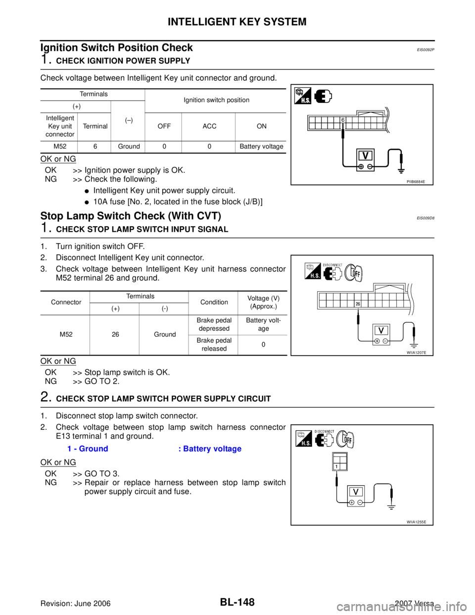
1. CHECK IGNITION POWER SUPPLY
Check voltage between Intelligent Key unit connector and ground.
OK or NG
OK >> Ignition power supply is OK.
NG >> Check the following.
�Intelligent Key unit power supply circuit.
�10A fuse [No. 2, located in the fuse block (J/B)]
Stop Lamp Switch Check (With CVT)EIS0 09 D8
1. CHECK STOP LAMP SWITCH INPUT SIGNAL
1. Turn ignition switch OFF.
2. Disconnect Intelligent Key unit connector.
3. Check voltage between Intelligent Key unit harness connector
M52 terminal 26 and ground.
OK or NG
OK >> Stop lamp switch is OK.
NG >> GO TO 2.
2. CHECK STOP LAMP SWITCH POWER SUPPLY CIRCUIT
1. Disconnect stop lamp switch connector.
2. Check voltage between stop lamp switch harness connector
E13 terminal 1 and ground.
OK or NG
OK >> GO TO 3.
NG >> Repair or replace harness between stop lamp switch
power supply circuit and fuse.
Te r m i n a l s
Ignition switch position
(+)
(–) Intelligent
Key unit
connectorTe r m i n a l O F F A C C O N
M52 6 Ground 0 0 Battery voltage
PIIB6884E
ConnectorTe r m i n a l s
ConditionVoltage (V)
(Approx.)
(+) (-)
M52 26 GroundBrake pedal
depressedBattery volt-
age
Brake pedal
released0
WIIA1207E
1 - Ground : Battery voltage
WIIA1255E