Page 3 of 130
 “AIR BAG” and “SEAT
BELT PRE-TENSIONER”
NI")
PRECAUTIONS
RF-3
C
D
E
F
G
H
J
K
L
MA
B
RF
Revision: 2006 November2007 350Z
PRECAUTIONSPFP:00001
Precautions for Supplemental Restraint System (SRS) “AIR BAG” and “SEAT
BELT PRE-TENSIONER”
NIS00063
The Supplemental Restraint System such as “AIR BAG” and “SEAT BELT PRE-TENSIONER”, used along
with a front seat belt, helps to reduce the risk or severity of injury to the driver and front passenger for certain
types of collision. This system includes seat belt switch inputs and dual stage front air bag modules. The SRS
system uses the seat belt switches to determine the front air bag deployment, and may only deploy one front
air bag, depending on the severity of a collision and whether the front occupants are belted or unbelted.
Information necessary to service the system safely is included in the SRS and SB section of this Service Man-
ual.
WARNING:
�To avoid rendering the SRS inoperative, which could increase the risk of personal injury or death
in the event of a collision which would result in air bag inflation, all maintenance must be per-
formed by an authorized NISSAN/INFINITI dealer.
�Improper maintenance, including incorrect removal and installation of the SRS, can lead to per-
sonal injury caused by unintentional activation of the system. For removal of Spiral Cable and Air
Bag Module, see the SRS section.
�Do not use electrical test equipment on any circuit related to the SRS unless instructed to in this
Service Manual. SRS wiring harnesses can be identified by yellow and/or orange harnesses or
harness connectors.
Precautions for Battery ServiceNIS00064
Before disconnecting the battery, lower both the driver and passenger windows. This will prevent any interfer-
ence between the window edge and the vehicle when the door is opened/closed. During normal operation, the
window slightly raises and lowers automatically to prevent any window to vehicle interference. The automatic
window function will not work with the battery disconnected.
Precautions NIS00065
�Disconnect both battery cables in advance.
�Never tamper with or force air bag lid open, as this may adversely affect air bag performance.
�Be careful not to scratch pad and other parts.
�When removing or disassembling any part, be careful not to damage or deform it. Protect parts, which
may get in the way with cloth.
�When removing parts with a screwdriver or other tool, protect parts by wrapping them with vinyl or tape.
�Keep removed parts protected with cloth.
�If a clip is deformed or damaged, replace it.
�If an unreusable part is removed, replace it with a new one.
�Tighten bolts and nuts firmly to the specified torque.
�After re-assembly has been completed, make sure each part functions correctly.
�Remove stains in the following way.
Water-soluble stains:
Dip a soft cloth in warm water, and then squeeze it tightly. After wiping the stain, wipe with a soft dry cloth.
Oil stain:
Dissolve a synthetic detergent in warm water (density of 2 to 3% or less), dip the cloth, then clean off the stain
with the cloth. Next, dip the cloth in fresh water and squeeze it tightly. Then clean off the detergent completely.
Then wipe the area with a soft dry cloth.
Do not use any organic solvent, such as thinner or benzine.
Page 86 of 130

RF-86
SOFT TOP
Revision: 2006 November2007 350Z
3. CHECK INDICATOR LAMP CIRCUIT
1. Turn ignition switch OFF.
2. Disconnect soft top control unit and combination meter connector.
3. Check continuity between soft top control unit connector B67
terminal 35 and combination meter connector M19 terminal 13.
4. Check continuity between soft top control unit connector B67
terminal 35 and ground.
OK or NG
OK >> GO TO 4.
NG >> Repair or replace harness.
4. CHECK INDICATOR LAMP POWER SUPPLY
1. Turn ignition switch ON.
2. Check voltage between combination meter connector M19 ter-
minal 23 and ground.
OK or NG
OK >> Check the Condition of the Harness and the Connector.
�If OK: Replace combination meter.
�If NG: Repair or replace harness.
NG >> Repair or replace harness.
Removal and Installation of Soft Top Control UnitNIS0007P
REMOVAL
1. Push the soft top switch on the close side to clear the soft top storage room, and release the buttom
before strage lid starts closing.
2. Remove trim parts and turn the front side of storage room finisher. RF-126, "
Removal and Installation of
Storage Room Finisher"
3. Disconnect soft top control unit connector, remove the screw
and soft top control unit.
INSTALLATION
Installation in the reverse order of removal.35 (Y) – 13 (G/W) : Continuity should exist.
35 (Y) – Ground : Continuity should not exist.
PIIB0836E
23 (G/Y) – Ground : Battery voltage
PIIB0837E
PIIB0838E
Page 88 of 130

RF-88
SOFT TOP
Revision: 2006 November2007 350Z
Removal and Installation of Soft Top AssemblyNIS0007R
CAUTION:
Install fender cover to protect rear fender.
REMOVAL
1. Fully open storage lid with soft top retracting.
2. Remove seat belt sholder bolt. Refer to SB-6, "
REMOVAL OF SEAT BELT RETRACTOR" .
3. Remove rear side finisher. Refer to EI-37, "
REAR SIDE FINISHER" .
4. Remove back panel finisher. Refer to EI-42, "
BACK PANEL FINISHER" .
5. Loosen bolts at soft top mounting bracket (front).
CAUTION:
Do not remove soft top mounting bracket (front) (body
side).
6. Close soft top until 5th bow are raised and folded with C-link.
Loosen nut at soft top mounting bracket (rear). Then fold (open)
soft top assembly completely.
CAUTION:
Do not remove soft top mounting bracket (rear) (body side).
7. Remove back panel bracket.
1. Front lock 2. Front lock finisher 3. TORX bolt (T30)
4. Welt 5. Front center retainer 6. Clip
7. Screw 8. Front lock striker, RH 9. Front lock striker, center
10. Front lock striker, LH 11. Bolt 12. B link retainer
13. A link retainer 14. A link weather strip 15. B link weather-strip
16. C link and 5th bow weather strip 17. Soft top switch bracket 1 18. Soft top switch bracket 2
19. C link retainer 20. Plate rail RR bracket 21. 5th bow operating strut rod
22. Nut 23. Holder 24. Soft top frame
25. Soft top cover 26. 5th bow retainer 27. 1st bow
28. 2nd bow 29. 3rd bow 30. 4th bow
31. 5th bow 32. A link 33. B link
34. C link
Nut: 28.0 N·m (2.9 kg-m, 21 ft-lb)
PIIA7824E
Bolt: 28.0 N·m (2.9 kg-m, 21 ft-lb)
PIIA7877E
Page 89 of 130

SOFT TOP
RF-89
C
D
E
F
G
H
J
K
L
MA
B
RF
Revision: 2006 November2007 350Z
8. Remove bolts, at the soft top mounting plate and shims.
CAUTION:
Do not replace left and right shims with each one with dif-
ferent thickness.
9. Disconnect harness connector.
10. Lift up soft top assembly from left and right, and then remove soft top assembly.
CAUTION:
2 workers are required for the heavy load of approximately 40 kg (89 lb).
INSTALLATION
Install in the reverse order of removal except the order of tightening bolts and nuts. (See note below.)
NOTE:
Before tighten soft top fixing bolts and nuts, make sure that soft top is sat on each pins from soft top mounting
brackets without any gaps.
To sit soft top correctly, follow this order.
1. Push soft top assembly down when nuts at soft top mounting bracket (rear) is tighten.
2. Close soft top until the angle of A-link becomes vertical against ground, then tighten bolts at soft top
mounting bracket (front).
3. Tighten bolts at soft top mounting plate with shims, then attach back panel bracket with bolts. Bolt: 28.0 N·m (2.9 kg-m, 21 ft-lb)
PIIA7863E
PIIA7878E
PIIB1302E
Page 90 of 130
RF-90
SOFT TOP
Revision: 2006 November2007 350Z
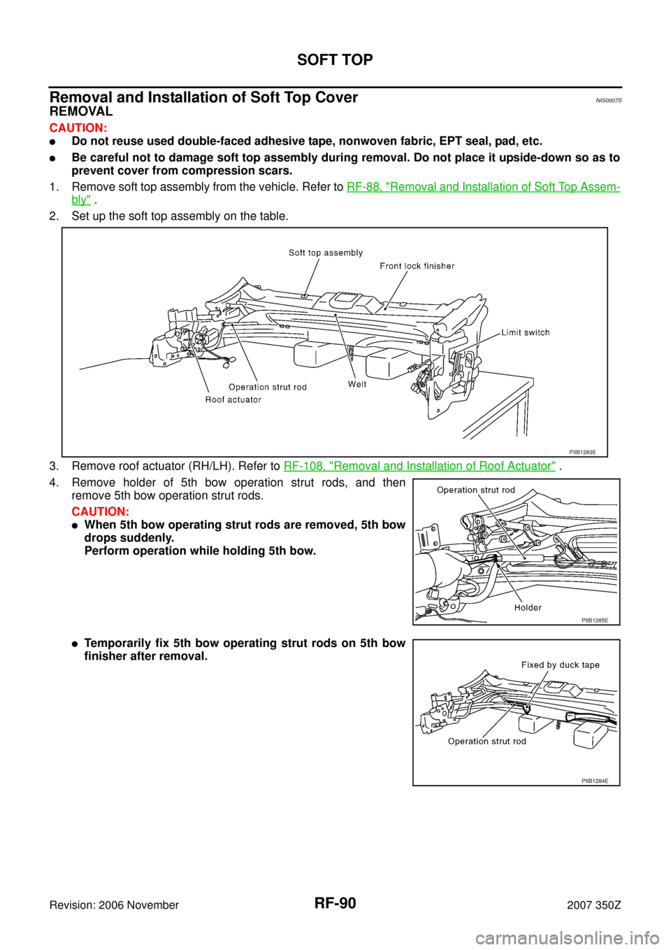
Removal and Installation of Soft Top CoverNIS0007S
REMOVAL
CAUTION:
�Do not reuse used double-faced adhesive tape, nonwoven fabric, EPT seal, pad, etc.
�Be careful not to damage soft top assembly during removal. Do not place it upside-down so as to
prevent cover from compression scars.
1. Remove soft top assembly from the vehicle. Refer to RF-88, "
Removal and Installation of Soft Top Assem-
bly" .
2. Set up the soft top assembly on the table.
3. Remove roof actuator (RH/LH). Refer to RF-108, "
Removal and Installation of Roof Actuator" .
4. Remove holder of 5th bow operation strut rods, and then
remove 5th bow operation strut rods.
CAUTION:
�When 5th bow operating strut rods are removed, 5th bow
drops suddenly.
Perform operation while holding 5th bow.
�Temporarily fix 5th bow operating strut rods on 5th bow
finisher after removal.
PIIB1283E
PIIB1285E
PIIB1284E
Page 91 of 130
SOFT TOP
RF-91
C
D
E
F
G
H
J
K
L
MA
B
RF
Revision: 2006 November2007 350Z
5. Open soft top assembly.
6. Protect the limit switch contact around the rotation axis of the 5th
bow on the left side of soft top with tape.
7. Remove welt on the rear end of front lock finisher.
8. Remove left/right clips on the front end of front lock finisher.
9. Pull up front lock lever, and then disengage clips to remove front
lock finisher.
PIIB1288E
PIIB1286E
PIIA7809E
PIIB1287E
PIIB1303E
Page 92 of 130
RF-92
SOFT TOP
Revision: 2006 November2007 350Z
10. Remove clip, and then A link weather strip.
11. Peel a link sealing out.
12. Remove screws, and then remove front center retainer.
13. Put matching marks to installation position of A link retainer.
14. Remove screws, and then remove A link retainer.
PIIB1289E
PIIB1291E
PIIB1290E
PIIB1292E
Page 93 of 130
SOFT TOP
RF-93
C
D
E
F
G
H
J
K
L
MA
B
RF
Revision: 2006 November2007 350Z
15. Open soft top about 90 degrees.
16. Remove clips on the top of C link and 5th bow weather strip.
17. Fully open soft top.
18. Put matching marks to installation position on C link retainer.
19. Remove screws, and then remove C link retainer.
20. Remove clips on the bottom edge of C link and 5th bow weath-
erstrip.
PIIB1288E
PIIB1293E
PIIB1295E
PIIB1294E