Page 9 of 40
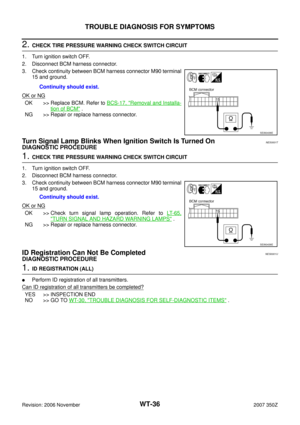
ROAD WHEEL TIRE ASSEMBLY
WT-9
C
D
F
G
H
I
J
K
L
MA
B
WT
Revision: 2006 November2007 350Z
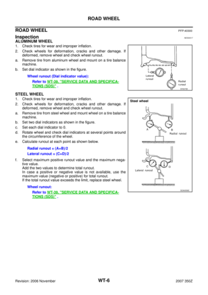
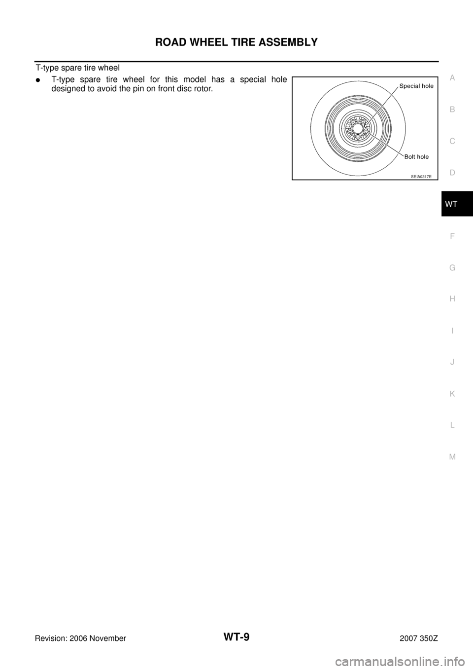
T-type spare tire wheel
�T-type spare tire wheel for this model has a special hole
designed to avoid the pin on front disc rotor.
SEIA0317E
Page 10 of 40
WT-10
TIRE PRESSURE MONITORING SYSTEM
Revision: 2006 November2007 350Z
TIRE PRESSURE MONITORING SYSTEMPFP:40300
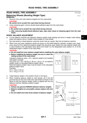
System ComponentsNES0001A
System DescriptionNES0001B
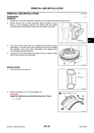
TRANSMITTER
A sensor-transmitter (1) integrated with a valve is installed on a
wheel (2), and transmits a detected air pressure signal in the form of
a radio wave.
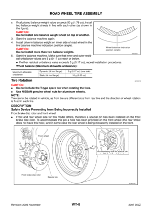
REMOTE KEYLESS ENTRY RECEIVER
The remote keyless entry receiver receives the air pressure signal
transmitted by the transmitter in each wheel.
SEIA0582E
: Outside
SEIA0768E
SEIA0431E
Page 11 of 40
TIRE PRESSURE MONITORING SYSTEM
WT-11
C
D
F
G
H
I
J
K
L
MA
B
WT
Revision: 2006 November2007 350Z
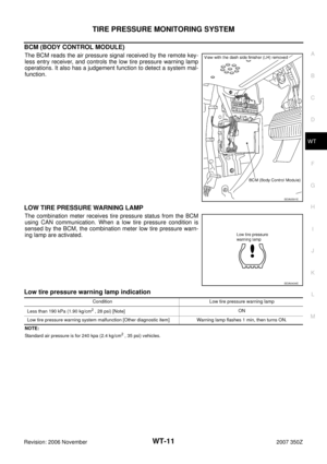
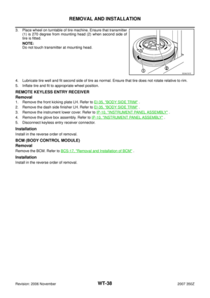
BCM (BODY CONTROL MODULE)
The BCM reads the air pressure signal received by the remote key-
less entry receiver, and controls the low tire pressure warning lamp
operations. It also has a judgement function to detect a system mal-
function.
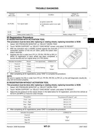
LOW TIRE PRESSURE WARNING LAMP
The combination meter receives tire pressure status from the BCM
using CAN communication. When a low tire pressure condition is
sensed by the BCM, the combination meter low tire pressure warn-
ing lamp are activated.
Low tire pressure warning lamp indication
NOTE:
Standard air pressure is for 240 kpa (2.4 kg/cm2 , 35 psi) vehicles.
SEIA0591E
SEIA0434E
Condition Low tire pressure warning lamp
Less than 190 kPa (1.90 kg/cm
2 , 28 psi) [Note]ON
Low tire pressure warning system malfunction [Other diagnostic item] Warning lamp flashes 1 min, then turns ON.
Page 12 of 40
WT-12
TIRE PRESSURE MONITORING SYSTEM
Revision: 2006 November2007 350Z
Can CommunicationNES000A0
SYSTEM DESCRIPTION
CAN (Controller Area Network) is a serial communication line for real time application. It is an on-vehicle mul-
tiplex communication line with high data communication speed and excellent error detection ability. Many elec-
tronic control units are equipped onto a vehicle, and each control unit shares information and links with other
control units during operation (not independent). In CAN communication, control units are connected with 2
communication lines (CAN H line, CAN L line) allowing a high rate of information transmission with less wiring.
Each control unit transmits/receives data but selectively reads required data only. Refer to LAN-49, "
CAN
Communication Signal Chart" .
Page 13 of 40

TROUBLE DIAGNOSIS
WT-13
C
D
F
G
H
I
J
K
L
MA
B
WT
Revision: 2006 November2007 350Z
TROUBLE DIAGNOSISPFP:00004
How to Perform Trouble DiagnosisNES000AF
BASIC CONCEPT
�To perform trouble diagnosis, it is the most important to have understanding about vehicle systems (con-
trol and mechanism) thoroughly.
�It is also important to clarify customer complaints before inspec-
tion.
First of all, reproduce symptoms, and understand them fully.
Ask customer about his/her complaints carefully. In some cases,
it will be necessary to check symptoms by driving vehicle with
customer.
CAUTION:
Customers are not professional. It is dangerous to make an
easy guess like “maybe the customer means that...,” or
“maybe the customer mentions this symptom”.
�It is essential to check symptoms right from the beginning in
order to repair malfunctions completely.
For intermittent malfunctions, reproduce symptoms based on
interview with customer and past examples. Do not perform
inspection on ad hoc basis. Most intermittent malfunctions are
caused by poor contacts. In this case, it will be effective to shake
suspected harness or connector by hand. When repairing with-
out any symptom diagnosis, you cannot judge if malfunctions
have actually been eliminated.
�After completing diagnosis, always erase diagnostic memory.
�For intermittent malfunctions, move harness or harness connec-
tor by hand. Then check for poor contact or reproduced open cir-
cuit.
INTRODUCTION
�Before troubleshooting, verify customer complaints.
�If a vehicle malfunction is difficult to reproduce, harnesses, harness connectors or terminals may be mal-
functioning. Hold and shake these parts to make sure they are securely connected.
�When using a circuit tester to measure voltage or resistance of each circuit, be careful not to damage or
deform connector terminals.
SEF233G
SEF234G
Page 14 of 40
WT-14
TROUBLE DIAGNOSIS
Revision: 2006 November2007 350Z
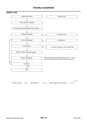
WORK FLOW
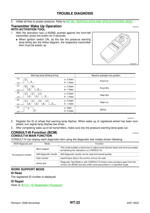
Preliminary check:WT-29Self-diagnosis:WT-23Trouble diagnosis for symptoms:WT-33
SEIA0100E
Page 15 of 40
TROUBLE DIAGNOSIS
WT-15
C
D
F
G
H
I
J
K
L
MA
B
WT
Revision: 2006 November2007 350Z
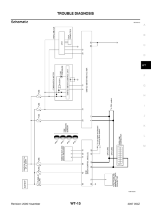
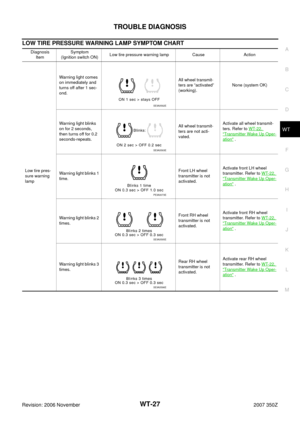
SchematicNES0001D
TEWT0020E
Page 16 of 40
WT-16
TROUBLE DIAGNOSIS
Revision: 2006 November2007 350Z
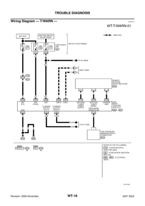
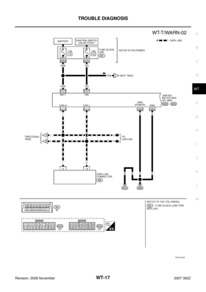
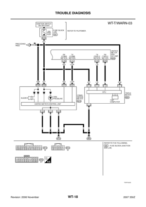
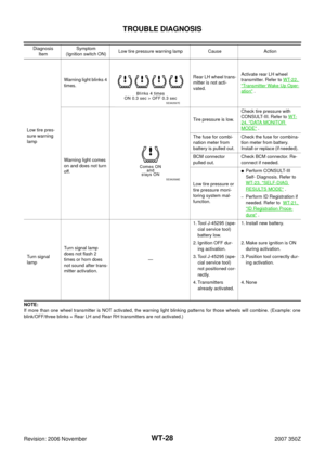
Wiring Diagram — T/WARN —NES0001E
TEWT0056E


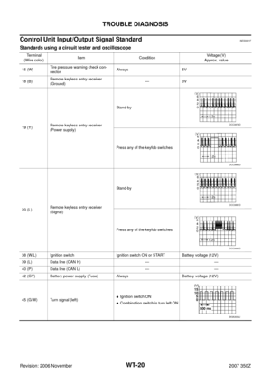


The BCM reads the air pressure signal received by the remote key-
less entry")
 is a serial communication line for real time applicati")


