Page 17 of 60
REAR FINAL DRIVE ASSEMBLY
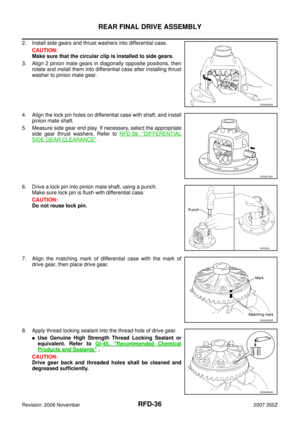
RFD-17
C
E
F
G
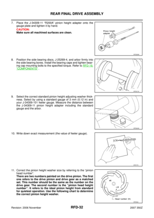
H
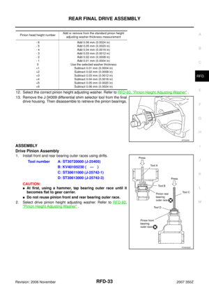
I
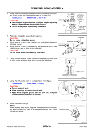
J
K
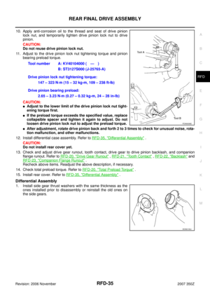
L
MA
B
RFD
Revision: 2006 November2007 350Z
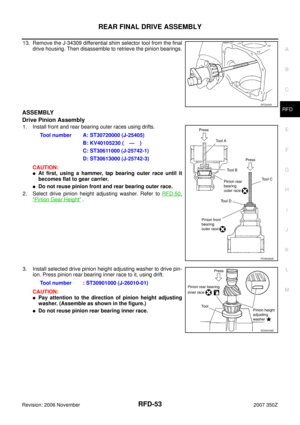
REAR FINAL DRIVE ASSEMBLYPFP:38300
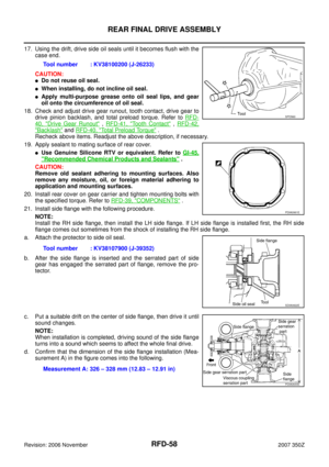
Removal and InstallationNDS0000I
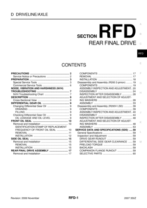
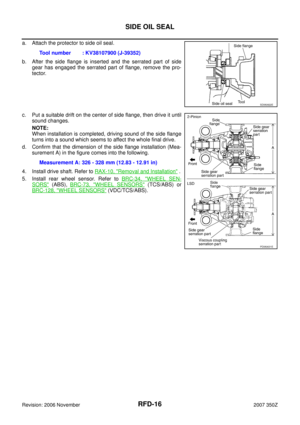
COMPONENTS
REMOVAL
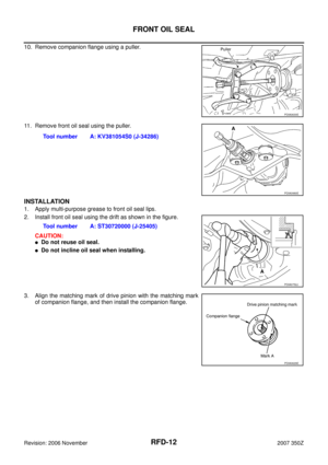
1. Remove propeller shaft from the final drive. Refer to PR-6, "Removal and Installation" .
CAUTION:
Do not impact or damage propeller shaft tube.
2. Remove rear stabilizer bar with a power tool. Refer to FSU-18, "
STABILIZER BAR" .
3. Remove drive shaft from final drive. Then suspend it by wire etc.
Refer to RAX-10, "
REAR DRIVE SHAFT" .
4. Remove breather hose from the final drive.
5. Remove rear wheel sensor. Refer to BRC-34, "
WHEEL SEN-
SORS" (ABS), BRC-73, "WHEEL SENSORS" (TCS/ABS) or
BRC-128, "
WHEEL SENSORS" (VDC/TCS/ABS).
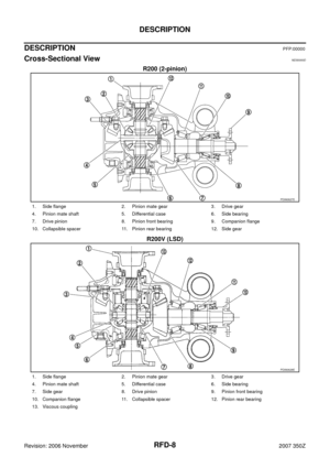
1. Rear final drive assembly 2. Upper stopper 3. Propeller shaft
4. Washer 5. Lower stopper 6. Drive shaft
PDIA0632E
SDIA1094E
Page 18 of 60
.
7. Remov")
RFD-18
REAR FINAL DRIVE ASSEMBLY
Revision: 2006 November2007 350Z
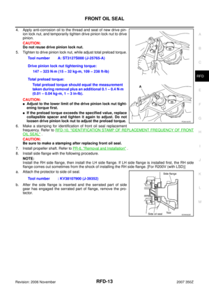
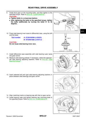
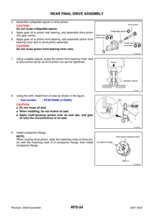
6. Set a suitable jack to rear final drive assembly.
CAUTION:
Do not place a suitable jack on the rear cover (aluminum
case).
7. Remove the mounting bolts and nuts connecting to the suspen-
sion member, and remove rear final drive assembly.
CAUTION:
Secure rear final drive assembly to a suitable jack while
removing it.
INSTALLATION
Note the following, and installation is in the reverse order of removal.
�Refer to RFD-19, "COMPONENTS" (R200 2-pinion) or RFD-39, "COMPONENTS" (R200V LSD) about
each tightening torque.
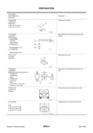
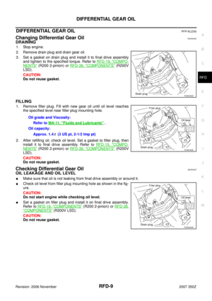
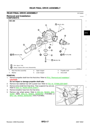
�When installing breather hoses, refer to the figure.
CAUTION:
Make sure there are no pinched or restricted areas on the
breather hose caused by bending or winding when install-
ing it.
–For installation, the vehicle side end shall be inserted to suspen-
sion member. Install metal connector side of this hose to rear
cover by inserting it with aiming painted marking to the front of
vehicle.
�When oil leaks while removing final drive assembly, check oil
level after the installation. Refer to RFD-9, "
Checking Differential
Gear Oil" .
PDIA0690E
SDIA1970J
PDIA0633E
Page 19 of 60
NDS0000J
COMPONENTS
1. Drive pinion lock nut 2. Companion flange 3.")
REAR FINAL DRIVE ASSEMBLY
RFD-19
C
E
F
G
H
I
J
K
L
MA
B
RFD
Revision: 2006 November2007 350Z
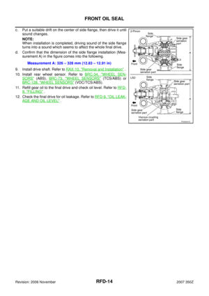
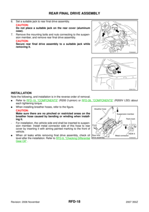
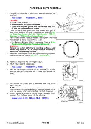
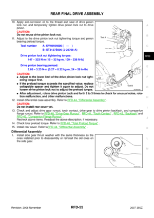
Disassembly and Assembly (R200 2-pinion)NDS0000J
COMPONENTS
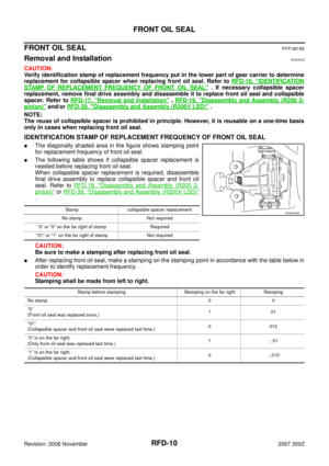
1. Drive pinion lock nut 2. Companion flange 3. Front oil seal
4. Pinion front bearing 5. Gear carrier 6. Side oil seal
7. Side flange 8. Collapsible spacer 9. Pinion rear bearing
10. Pinion height adjusting washer 11. Drive pinion 12. Side bearing adjusting washer
13. Side bearing 14. Side gear thrust washer 15. Circular clip
16. Side gear 17. Lock pin 18. Pinion mate gear
19. Pinion mate thrust washer 20. Pinion mate shaft 21. Drive gear
22. Differential case 23. Bearing cap 24. Filler plug
25. Gasket 26. Rear cover 27. Drain plug
A: Oil seal lip
B: Screw hole
C: After tightening the bolts to the specified torque, tighten the bolts additionally by turning the bolts 31 to 36 degrees.
Refer to GI-11, "
Components" and the followings for the symbols in the figure.
:Apply gear oil.
:Apply anti-corrosion oil.
:Apply Genuine Silicone RTV or equivalent. Refer to GI-45, "
Recommended Chemical Products and Sealants" .
:Apply Genuine High Strength Thread Locking Sealant or equivalent. Refer to GI-45, "
Recommended Chemical Prod-
ucts and Sealants" .
PDIA1134E
Page 20 of 60

RFD-20
REAR FINAL DRIVE ASSEMBLY
Revision: 2006 November2007 350Z
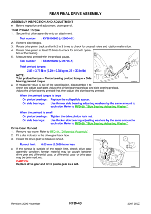
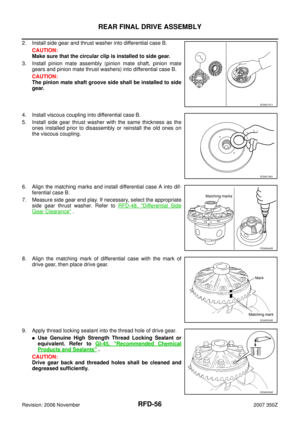
ASSEMBLY INSPECTION AND ADJUSTMENT
�Before inspection and adjustment, drain gear oil.
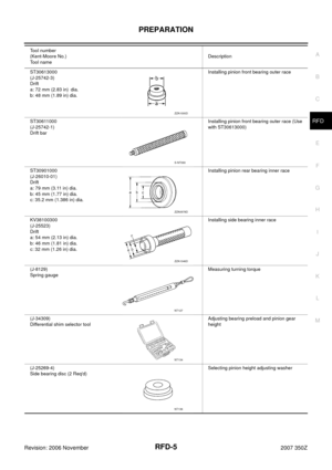
Total Preload Torque
1. Secure final drive assembly onto an attachment.
2. Remove side flanges.
3. Rotate drive pinion back and forth 2 to 3 times to check for unusual noise and rotation malfunction.
4. Rotate drive pinion at least 20 times to check for smooth opera-
tion of the bearing.
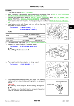
5. Measure total preload with the preload gauge.
NOTE:
Total preload torque = Pinion bearing preload torque + Side
bearing preload torque
�If measured value is out of the specification, disassemble it to
check and adjust each part. Adjust the pinion bearing preload and side bearing preload.
Adjust the pinion bearing preload first, then adjust the side bearing preload.
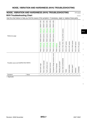
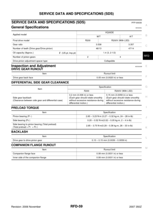
Drive Gear Runout
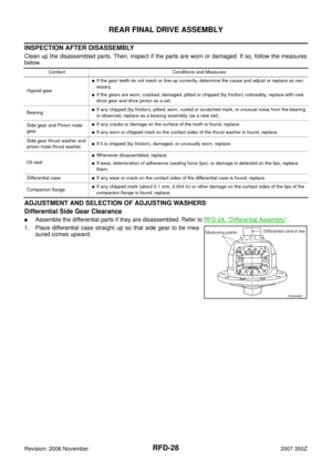
1. Remove rear cover. Refer to RFD-24, "Differential Assembly" .
2. Fit a dial indicator to the drive gear back face.
3. Rotate the drive gear to measure runout.
�If the runout is outside of the repair limit, check drive gear
assembly condition; foreign material may be caught between
drive gear and differential case, or differential case or drive gear
may be deformed, etc.
CAUTION:
Replace drive gear and drive pinion gear as a set.Tool number : KV38100800 (J-25604-01)
Tool number : ST3127S000 (J-25765-A)
Total preload torque:
2.85 – 3.75 N·m (0.29 – 0.38 kg-m, 26 – 33 in-lb)
PDIA0635E
When the preload torque is large
On pinion bearings: Replace the collapsible spacer.
On side bearings: Use thinner side bearing adjusting washers by the same amount to
each side. Refer to RFD-60, "
Side Bearing Adjusting Washer" .
When the preload is small
On pinion bearings: Tighten the drive pinion lock nut.
On side bearings: Use thicker side bearing adjusting washers by the same amount to
each side. Refer to RFD-60, "
Side Bearing Adjusting Washer" .
Runout limit: 0.05 mm (0.0020 in) or less
SPD886
Page 21 of 60
REAR FINAL DRIVE ASSEMBLY
RFD-21
C
E
F
G
H
I
J
K
L
MA
B
RFD
Revision: 2006 November2007 350Z
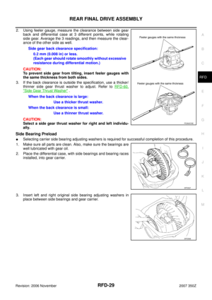
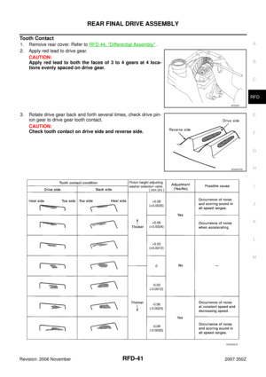
Tooth Contact
1. Remove rear cover. Refer to RFD-24, "Differential Assembly" .
2. Apply red lead to drive gear.
CAUTION:
Apply red lead to both the faces of 3 to 4 gears at 4 loca-
tions evenly spaced on drive gear.
3. Rotate drive gear back and forth several times, check drive pin-
ion gear to drive gear tooth contact.
CAUTION:
Check tooth contact on drive side and reverse side.
SPD357
SDIA0570E
SDIA0207E
Page 22 of 60
.
�If the tooth contac")
RFD-22
REAR FINAL DRIVE ASSEMBLY
Revision: 2006 November2007 350Z
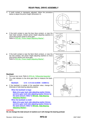
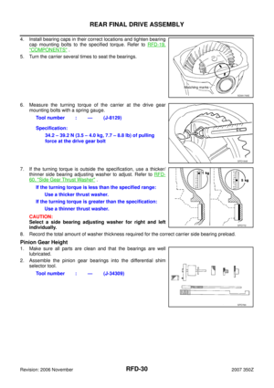
4. If tooth contact is improperly adjusted, follow the procedure
below to adjust the pinion height (dimension X).
�If the tooth contact is near the face (face contact), or near the
heel (heel contact), thicken pinion height adjusting washers to
move drive pinion closer to drive gear.
Refer to RFD-60, "
Pinion Height Adjusting Washer" .
�If the tooth contact is near the flank (flank contact), or near the
toe (toe contact), thin pinion height adjusting washers to move
drive pinion farther from drive gear.
Refer to RFD-60, "
Pinion Height Adjusting Washer" .
Backlash
1. Remove rear cover. Refer to RFD-24, "Differential Assembly" .
2. Fit a dial indicator to the drive gear face to measure the back-
lash.
�If the backlash is outside of the specified value, change the
thickness of side bearing adjusting washer.
CAUTION:
Do not change the total amount of washers as it will change the bearing preload.
SDIA0517E
PDIA0440E
PDIA0441E
Backlash: 0.10 – 0.15 mm (0.0039 – 0.0059 in)
When the backlash is large:
Make drive gear back side adjusting washer thicker,
and drive gear tooth side adjusting washer thinner by
the same amount. Refer to RFD-60, "
Side Bearing
Adjusting Washer" .
When the backlash is small:
Make drive gear back side adjusting washer thinner,
and drive gear tooth side adjusting washer thicker by
the same amount. Refer to RFD-60, "
Side Bearing
Adjusting Washer" .
SPD513
Page 23 of 60

REAR FINAL DRIVE ASSEMBLY
RFD-23
C
E
F
G
H
I
J
K
L
MA
B
RFD
Revision: 2006 November2007 350Z
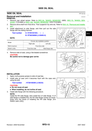
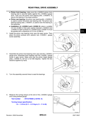
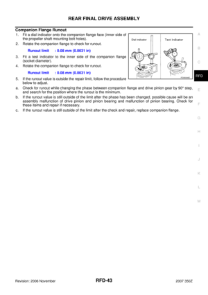
Companion Flange Runout
1. Fit a dial indicator onto the companion flange face (inner side of
the propeller shaft mounting bolt holes).
2. Rotate the companion flange to check for runout.
3. Fit a test indicator to the inner side of the companion flange
(socket diameter).
4. Rotate the companion flange to check for runout.
5. If the runout value is outside the repair limit, follow the procedure
below to adjust.
a. Check for runout while changing the phase between companion flange and drive pinion gear by 90° step,
and search for the position where the runout is the minimum.
b. If the runout value is still outside of the limit after the phase has been changed, possible cause will be an
assembly malfunction of drive pinion and pinion bearing and malfunction of pinion bearing. Check for
these items and repair if necessary.
c. If the runout value is still outside of the limit after the check and repair, replace companion flange.Runout limit : 0.08 mm (0.0031 in)
Runout limit : 0.08 mm (0.0031 in)
PDIA0646E
Page 24 of 60
RFD-24
REAR FINAL DRIVE ASSEMBLY
Revision: 2006 November2007 350Z
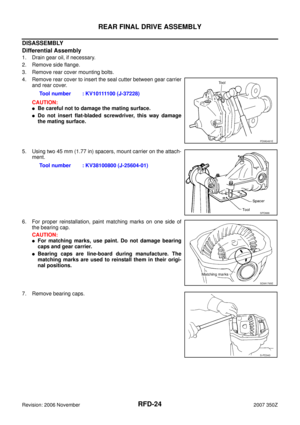
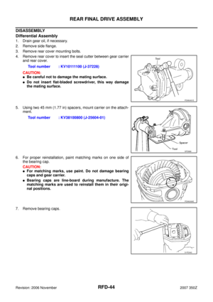
DISASSEMBLY
Differential Assembly
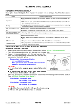
1. Drain gear oil, if necessary.
2. Remove side flange.
3. Remove rear cover mounting bolts.
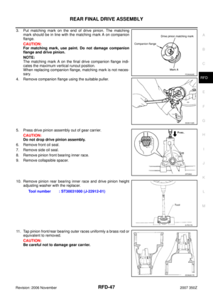
4. Remove rear cover to insert the seal cutter between gear carrier
and rear cover.
CAUTION:
�Be careful not to damage the mating surface.
�Do not insert flat-bladed screwdriver, this way damage
the mating surface.
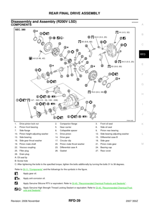
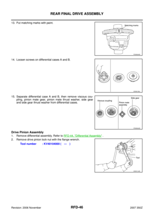
5. Using two 45 mm (1.77 in) spacers, mount carrier on the attach-
ment.
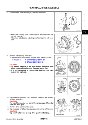
6. For proper reinstallation, paint matching marks on one side of
the bearing cap.
CAUTION:
�For matching marks, use paint. Do not damage bearing
caps and gear carrier.
�Bearing caps are line-board during manufacture. The
matching marks are used to reinstall them in their origi-
nal positions.
7. Remove bearing caps.Tool number : KV10111100 (J-37228)
PDIA0491E
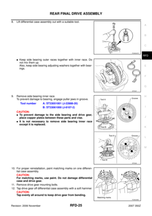
Tool number : KV38100800 (J-25604-01)
SPD888
SDIA1795E
S-PD343