Page 49 of 60

REAR FINAL DRIVE ASSEMBLY
RFD-49
C
E
F
G
H
I
J
K
L
MA
B
RFD
Revision: 2006 November2007 350Z
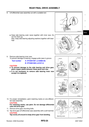
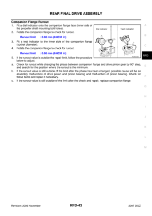
Side Bearing Preload
�Selecting carrier side bearing adjusting washers is required for successful completion of this procedure.
1. Make sure all parts are clean. Also, make sure the bearings are
well lubricated with gear oil.
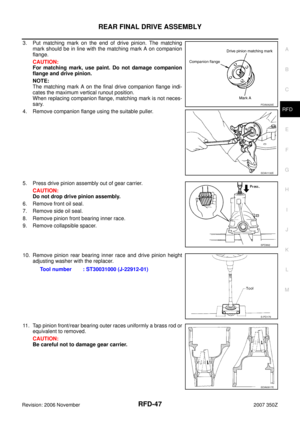
2. Place the differential case, with side bearings and bearing races
installed, into gear carrier.
3. Insert left and right original side bearing adjusting washers in
place between side bearings and gear carrier.
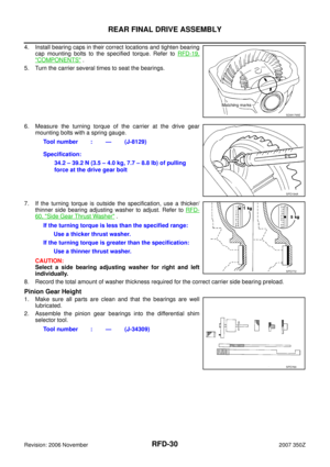
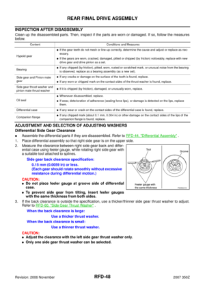
4. Install bearing caps in their correct locations and tighten bearing
cap mounting bolts to the specified torque. Refer to RFD-55,
"Differential Assembly" .
5. Turn the carrier several times to seat the bearings.
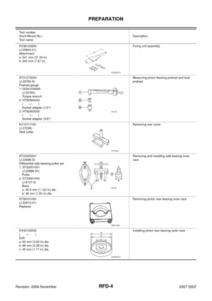
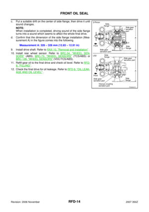
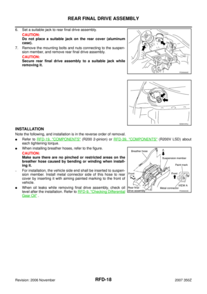
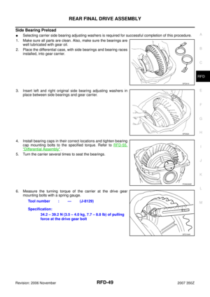
6. Measure the turning torque of the carrier at the drive gear
mounting bolts with a spring gauge.
SPD919
SPD924
PDIA0069E
Tool number : — (J-8129)
Specification:
34.2 – 39.2 N (3.5 – 4.0 kg, 7.7 – 8.8 lb) of pulling
force at the drive gear bolt
SPD194A
Page 50 of 60

RFD-50
REAR FINAL DRIVE ASSEMBLY
Revision: 2006 November2007 350Z
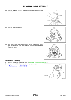
7. If the turning torque is outside the specification, use a thicker/
thinner side bearing adjusting washer to adjust. Refer to RFD-
60, "Side Bearing Adjusting Washer" .
CAUTION:
Select a side bearing adjusting washer for right and left
individually.
8. Record the total amount of washer thickness required for the correct carrier side bearing preload.
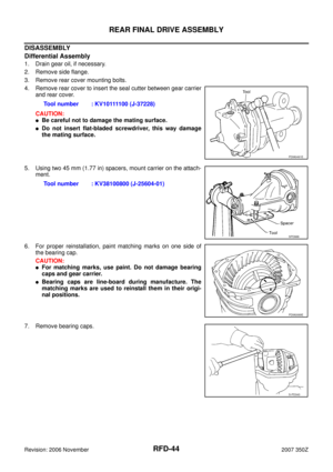
Pinion Gear Height
1. Make sure all parts are clean and that the bearings are well
lubricated.
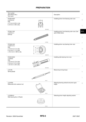
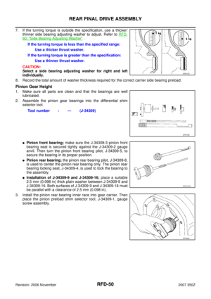
2. Assemble the pinion gear bearings into the differential shim
selector tool.
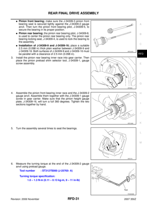
�Pinion front bearing; make sure the J-34309-3 pinion front
bearing seat is secured tightly against the J-34309-2 gauge
anvil. Then turn the pinion front bearing pilot, J-34309-5, to
secure the bearing in its proper position.
�Pinion rear bearing; the pinion rear bearing pilot, J-34309-8,
is used to center the pinion rear bearing only. The pinion rear
bearing locking seat, J-34309-4, is used to lock the bearing to
the assembly.
�Installation of J-34309-9 and J-34309-16; place a suitable
2.5 mm (0.098 in) thick plain washer between J-34309-9 and
J-34309-16. Both surfaces of J-34309-9 and J-34309-16 must
be parallel with a clearance of 2.5 mm (0.098 in).
3. Install the pinion rear bearing inner race into gear carrier. Then
place the pinion preload shim selector tool, J-34309-1, gauge
screw assembly.If the turning torque is less than the specified range:
Use a thicker thrust washer.
If the turning torque is greater than the specification:
Use a thinner thrust washer.
SPD772
Tool number : — (J-34309)
SPD769
SPD197A
SPD893
Page 51 of 60

REAR FINAL DRIVE ASSEMBLY
RFD-51
C
E
F
G
H
I
J
K
L
MA
B
RFD
Revision: 2006 November2007 350Z
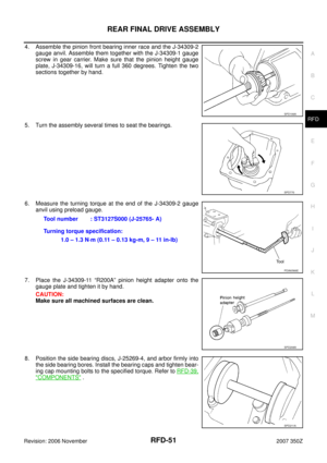
4. Assemble the pinion front bearing inner race and the J-34309-2
gauge anvil. Assemble them together with the J-34309-1 gauge
screw in gear carrier. Make sure that the pinion height gauge
plate, J-34309-16, will turn a full 360 degrees. Tighten the two
sections together by hand.
5. Turn the assembly several times to seat the bearings.
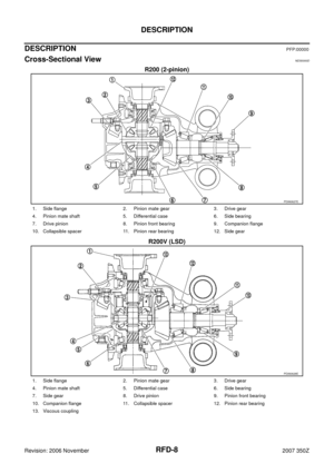
6. Measure the turning torque at the end of the J-34309-2 gauge
anvil using preload gauge.
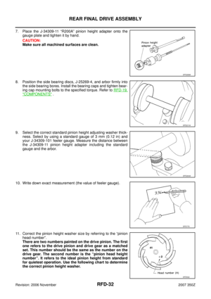
7. Place the J-34309-11 “R200A” pinion height adapter onto the
gauge plate and tighten it by hand.
CAUTION:
Make sure all machined surfaces are clean.
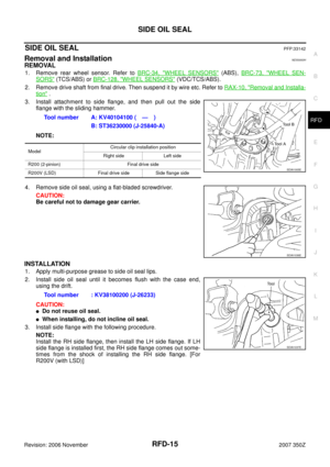
8. Position the side bearing discs, J-25269-4, and arbor firmly into
the side bearing bores. Install the bearing caps and tighten bear-
ing cap mounting bolts to the specified torque. Refer to RFD-39,
"COMPONENTS" .
SPD199A
SPD770
Tool number : ST3127S000 (J-25765- A)
Turning torque specification:
1.0 – 1.3 N·m (0.11 – 0.13 kg-m, 9 – 11 in-lb)
PDIA0566E
SPD208A
SPD211A
Page 52 of 60
 and
your")
RFD-52
REAR FINAL DRIVE ASSEMBLY
Revision: 2006 November2007 350Z
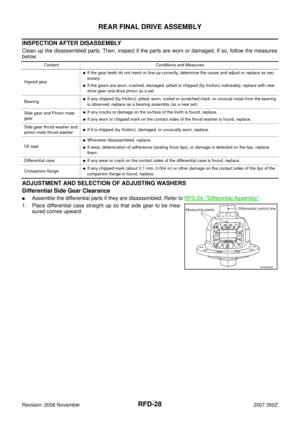
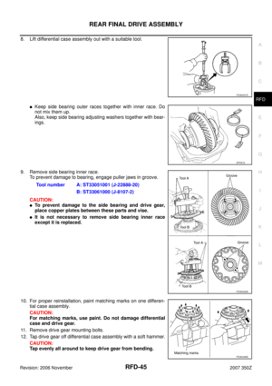
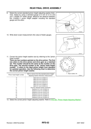
9. Select the correct standard pinion height adjusting washer thick-
ness. Select by using a standard gauge of 3 mm (0.12 in) and
your J-34309-101 feeler gauge. Measure the distance between
the J-34309-11 pinion height adapter including the standard
gauge and the arbor.
10. Write down exact measurement (the value of feeler gauge).
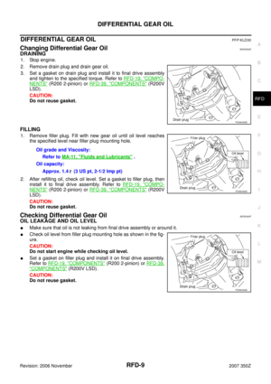
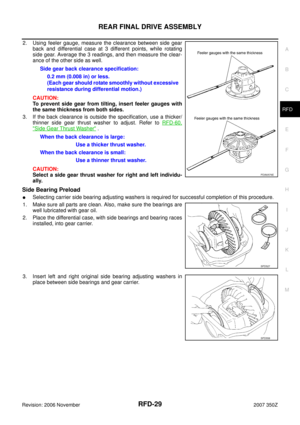
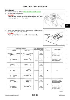
11. Correct the pinion height washer size by referring to the “pinion
head number”.
There are two numbers painted on the drive pinion. The first
one refers to the drive pinion and drive gear as a matched
set. This number should be the same as the number on the
drive gear. The second number is the “pinion head height
number”. It refers to the ideal pinion height from standard
for quietest operation. Use the following chart to determine
the correct pinion height washer.
12. Select the correct pinion height adjusting washer. Refer to RFD-60, "
Pinion Height Adjusting Washer" .
SPD204A
SPD775
Pinion head height numberAdd or remove from the standard pinion height
adjusting washer thickness measurement
- 6
- 5
- 4
- 3
- 2
- 1
0
+1
+2
+3
+4
+5
+6Add 0.06 mm (0.0024 in)
Add 0.05 mm (0.0020 in)
Add 0.04 mm (0.0016 in)
Add 0.03 mm (0.0012 in)
Add 0.02 mm (0.0008 in)
Add 0.01 mm (0.0004 in)
Use the selected washer thickness
Subtract 0.01 mm (0.0004 in)
Subtract 0.02 mm (0.0008 in)
Subtract 0.03 mm (0.0012 in)
Subtract 0.04 mm (0.0016 in)
Subtract 0.05 mm (0.0020 in)
Subtract 0.06 mm (0.0024 in)SPD542
Page 53 of 60

REAR FINAL DRIVE ASSEMBLY
RFD-53
C
E
F
G
H
I
J
K
L
MA
B
RFD
Revision: 2006 November2007 350Z
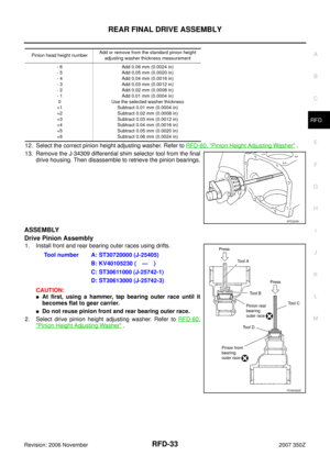
13. Remove the J-34309 differential shim selector tool from the final
drive housing. Then disassemble to retrieve the pinion bearings.
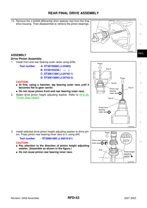
ASSEMBLY
Drive Pinion Assembly
1. Install front and rear bearing outer races using drifts.
CAUTION:
�At first, using a hammer, tap bearing outer race until it
becomes flat to gear carrier.
�Do not reuse pinion front and rear bearing outer race.
2. Select drive pinion height adjusting washer. Refer to RFD-50,
"Pinion Gear Height" .
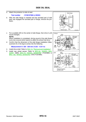
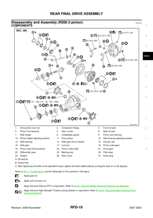
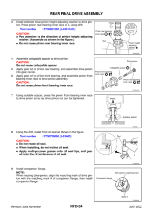
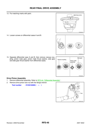
3. Install selected drive pinion height adjusting washer to drive pin-
ion. Press pinion rear bearing inner race to it, using drift.
CAUTION:
�Pay attention to the direction of pinion height adjusting
washer. (Assemble as shown in the figure.)
�Do not reuse pinion rear bearing inner race.
SPD205A
Tool number A: ST30720000 (J-25405)
B: KV40105230 ( — )
C: ST30611000 (J-25742-1)
D: ST30613000 (J-25742-3)
PDIA0562E
Tool number : ST30901000 (J-26010-01)
SDIA0048E
Page 54 of 60

RFD-54
REAR FINAL DRIVE ASSEMBLY
Revision: 2006 November2007 350Z
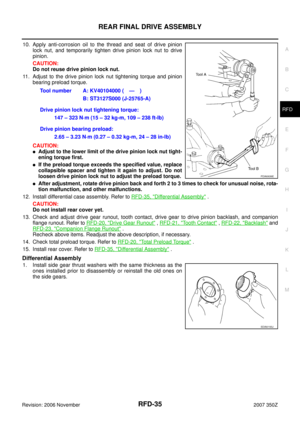
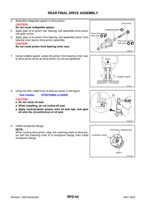
4. Assemble collapsible spacer to drive pinion.
CAUTION:
Do not reuse collapsible spacer.
5. Apply gear oil to pinion rear bearing, and assemble drive pinion
into gear carrier.
6. Apply gear oil to pinion front bearing, and assemble pinion front
bearing inner race to drive pinion assembly.
CAUTION:
Do not reuse pinion front bearing inner race.
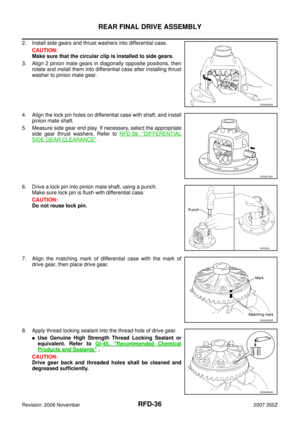
7. Using suitable spacer, press the pinion front bearing inner race
to drive pinion as far as drive pinion nut can be tightened.
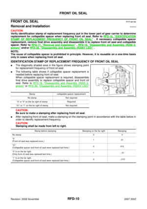
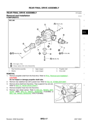
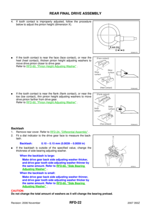
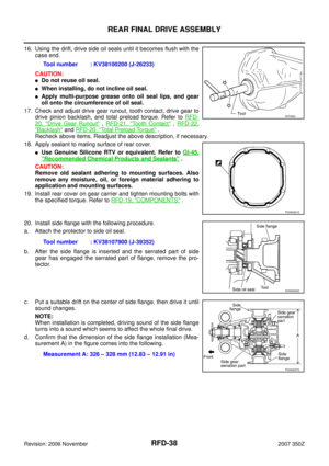
8. Using the drift, install front oil seal as shown in the figure.
CAUTION:
�Do not reuse oil seal.
�When installing, do not incline oil seal.
�Apply multi-purpose grease onto oil seal lips, and gear
oil onto the circumference of oil seal.
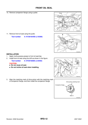
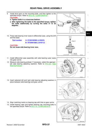
9. Install companion flange.
NOTE:
When reusing drive pinion, align the matching mark of drive pin-
ion with the matching mark A of companion flange, then install
companion flange.
PDIA0492E
SPD896
Tool number : ST30720000 (J-25405)
PDIA0563E
PDIA0629E
Page 55 of 60

REAR FINAL DRIVE ASSEMBLY
RFD-55
C
E
F
G
H
I
J
K
L
MA
B
RFD
Revision: 2006 November2007 350Z
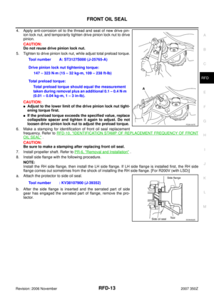
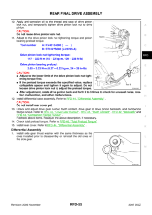
10. Apply anti-corrosion oil to the thread and seat of drive pinion
lock nut, and temporarily tighten drive pinion lock nut to drive
pinion.
CAUTION:
Do not reuse drive pinion lock nut.
11. Adjust to the drive pinion lock nut tightening torque and pinion
bearing preload torque.
CAUTION:
�Adjust to the lower limit of the drive pinion lock nut tight-
ening torque first.
�If the preload torque exceeds the specified value, replace
collapsible spacer and tighten it again to adjust. Do not
loosen drive pinion lock nut to adjust the preload torque.
�After adjustment, rotate drive pinion back and forth 2 to 3 times to check for unusual noise, rota-
tion malfunction, and other malfunctions.
12. Install differential case assembly. Refer to RFD-44, "
Differential Assembly" .
CAUTION:
Do not install rear cover yet.
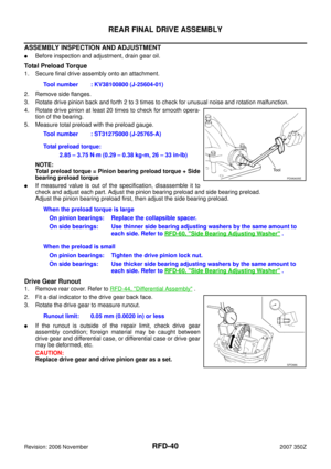
13. Check and adjust drive gear runout, tooth contact, drive gear to drive pinion backlash, and companion
flange runout. Refer to RFD-40, "
Drive Gear Runout" , RFD-41, "Tooth Contact" , RFD-42, "Backlash" and
RFD-43, "
Companion Flange Runout" .
Recheck above items. Readjust the above description, if necessary.
14. Check total preload torque. Refer to RFD-40, "
Total Preload Torque" .
15. Install rear cover. Refer toRFD-44, "
Differential Assembly" .
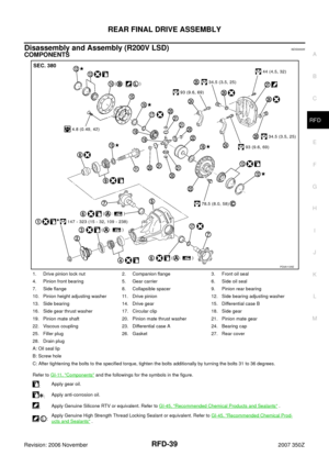
Differential Assembly
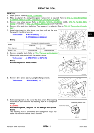
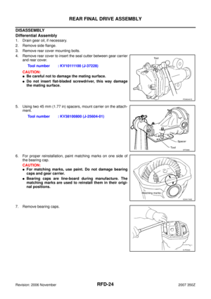
1. Install side gear thrust washer with the same thickness as the
ones installed prior to disassembly or reinstall the old ones on
the side gear.Tool number A: KV40104000 ( — )
B: ST3127S000 (J-25765-A)
Drive pinion lock nut tightening torque:
147 – 323 N·m (15 – 32 kg-m, 109 – 238 ft-lb)
Drive pinion bearing preload:
2.65 – 3.23 N·m (0.27 – 0.32 kg-m, 24 – 28 in-lb)
PDIA0636E
SDIA0196J
Page 56 of 60

RFD-56
REAR FINAL DRIVE ASSEMBLY
Revision: 2006 November2007 350Z
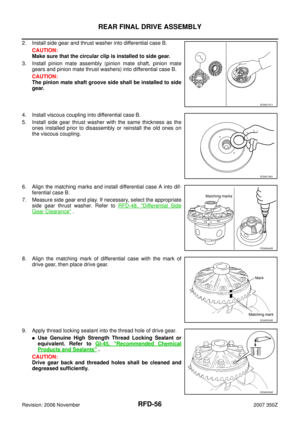
2. Install side gear and thrust washer into differential case B.
CAUTION:
Make sure that the circular clip is installed to side gear.
3. Install pinion mate assembly (pinion mate shaft, pinion mate
gears and pinion mate thrust washers) into differential case B.
CAUTION:
The pinion mate shaft groove side shall be installed to side
gear.
4. Install viscous coupling into differential case B.
5. Install side gear thrust washer with the same thickness as the
ones installed prior to disassembly or reinstall the old ones on
the viscous coupling.
6. Align the matching marks and install differential case A into dif-
ferential case B.
7. Measure side gear end play. If necessary, select the appropriate
side gear thrust washer. Refer to RFD-48, "
Differential Side
Gear Clearance" .
8. Align the matching mark of differential case with the mark of
drive gear, then place drive gear.
9. Apply thread locking sealant into the thread hole of drive gear.
�Use Genuine High Strength Thread Locking Sealant or
equivalent. Refer to GI-45, "
Recommended Chemical
Products and Sealants" .
CAUTION:
Drive gear back and threaded holes shall be cleaned and
degreased sufficiently.
SDIA0197J
SDIA0198J
PDIA0643E
SDIA2593E
SDIA2594E