Page 9 of 60

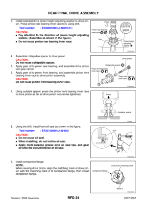
DIFFERENTIAL GEAR OIL
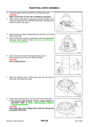
RFD-9
C
E
F
G
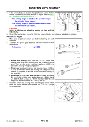
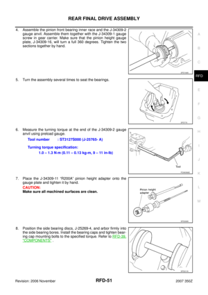
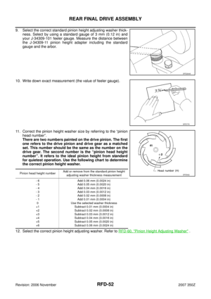
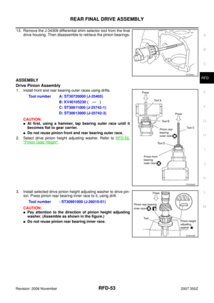
H
I
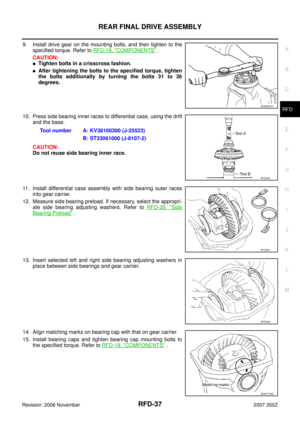
J
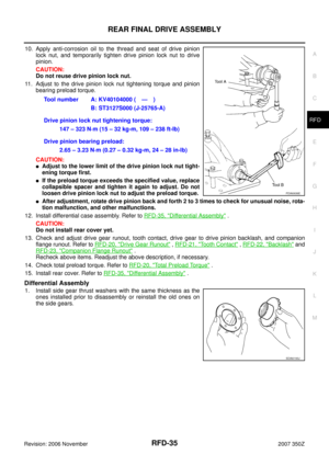
K
L
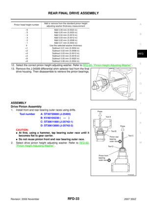
MA
B
RFD
Revision: 2006 November2007 350Z
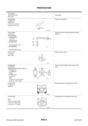
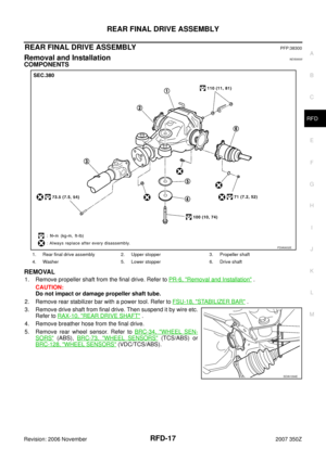
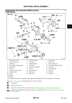
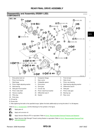
DIFFERENTIAL GEAR OILPFP:KLD30
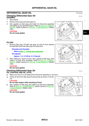
Changing Differential Gear OilNDS0000E
DRAINING
1. Stop engine.
2. Remove drain plug and drain gear oil.
3. Set a gasket on drain plug and install it to final drive assembly
and tighten to the specified torque. Refer to RFD-19, "
COMPO-
NENTS" (R200 2-pinion) or RFD-39, "COMPONENTS" (R200V
LSD).
CAUTION:
Do not reuse gasket.
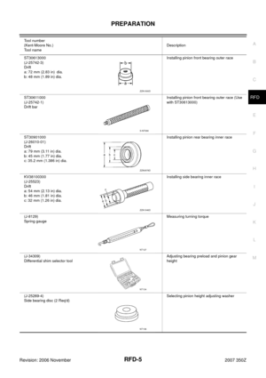
FILLING
1. Remove filler plug. Fill with new gear oil until oil level reaches
the specified level near filler plug mounting hole.
2. After refilling oil, check oil level. Set a gasket to filler plug, then
install it to final drive assembly. Refer to RFD-19, "
COMPO-
NENTS" (R200 2-pinion) or RFD-39, "COMPONENTS" (R200V
LSD).
CAUTION:
Do not reuse gasket.
Checking Differential Gear OilNDS0000F
OIL LEAKAGE AND OIL LEVEL
�Make sure that oil is not leaking from final drive assembly or around it.
�Check oil level from filler plug mounting hole as shown in the fig-
ure.
CAUTION:
Do not start engine while checking oil level.
�Set a gasket on filler plug and install it on final drive assembly.
Refer to RFD-19, "
COMPONENTS" (R200 2-pinion) or RFD-39,
"COMPONENTS" (R200V LSD).
CAUTION:
Do not reuse gasket.
PDIA0493E
Oil grade and Viscosity:
Refer to MA-11, "
Fluids and Lubricants" .
Oil capacity:
Approx. 1.4 (3 US pt, 2-1/2 Imp pt)
PDIA0494E
PDIA0494E
Page 10 of 60

RFD-10
FRONT OIL SEAL
Revision: 2006 November2007 350Z
FRONT OIL SEALPFP:38189
Removal and InstallationNDS0000G
CAUTION:
Verify identification stamp of replacement frequency put in the lower part of gear carrier to determine
replacement for collapsible spacer when replacing front oil seal. Refer to RFD-10, "
IDENTIFICATION
STAMP OF REPLACEMENT FREQUENCY OF FRONT OIL SEAL" . If necessary collapsible spacer
replacement, remove final drive assembly and disassemble it to replace front oil seal and collapsible
spacer. Refer to RFD-17, "
Removal and Installation" , RFD-19, "Disassembly and Assembly (R200 2-
pinion)" and/or RFD-39, "Disassembly and Assembly (R200V LSD)" .
NOTE:
The reuse of collapsible spacer is prohibited in principle. However, it is reusable on a one-time basis
only in cases when replacing front oil seal.
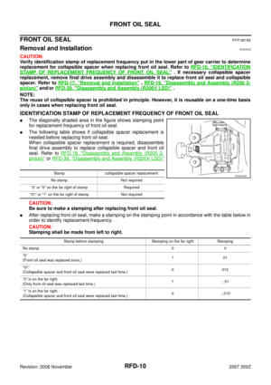
IDENTIFICATION STAMP OF REPLACEMENT FREQUENCY OF FRONT OIL SEAL
�The diagonally shaded area in the figure shows stamping point
for replacement frequency of front oil seal.
�The following table shows if collapsible spacer replacement is
needed before replacing front oil seal.
When collapsible spacer replacement is required, disassemble
final drive assembly to replace collapsible spacer and front oil
seal. Refer to RFD-19, "
Disassembly and Assembly (R200 2-
pinion)" or RFD-39, "Disassembly and Assembly (R200V LSD)"
.
CAUTION:
Be sure to make a stamping after replacing front oil seal.
�After replacing front oil seal, make a stamping on the stamping point in accordance with the table below in
order to identify replacement frequency.
CAUTION:
Stamping shall be made from left to right.
Stamp collapsible spacer replacement
No stamp Not required
“0” or “0” on the far right of stamp Required
“01” or “1” on the far right of stamp Not requiredPDIA0976E
Stamp before stamping Stamping on the far right Stamping
No stamp00
“0”
(Front oil seal was replaced once.)101
“01”
(Collapsible spacer and front oil seal were replaced last time.)0 010
“0” is on the far right.
(Only front oil seal was replaced last time.)1...01
“1” is on the far right.
(Collapsible spacer and front oil seal were replaced last time.)0 ...010
Page 11 of 60

FRONT OIL SEAL
RFD-11
C
E
F
G
H
I
J
K
L
MA
B
RFD
Revision: 2006 November2007 350Z
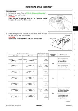
REMOVAL
1. Drain gear oil. Refer to RFD-9, "DRAINING" .
2. Make a judgment if a collapsible spacer replacement is required. Refer to RFD-10, "
IDENTIFICATION
STAMP OF REPLACEMENT FREQUENCY OF FRONT OIL SEAL" .
3. Remove rear wheel sensor. Refer to BRC-34, "
WHEEL SENSORS" (ABS),BRC-73, "WHEEL SEN-
SORS" (TCS/ABS) or BRC-128, "WHEEL SENSORS" (VDC/TCS/ABS).
4. Remove drive shaft from final drive. Then suspend it by wire etc. Refer to RAX-10, "
Removal and Installa-
tion" .
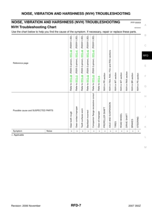
5. Install attachment to side flange, and then pull out the side
flange with the sliding hammer.
NOTE:
6. Remove propeller shaft. Refer to PR-6, "
Removal and Installation" .
7. Measure the total preload with the preload gauge.
NOTE:
Record the preload measurement.
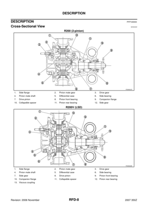
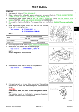
8. Remove drive pinion lock nut using the flange wrench.
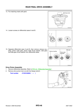
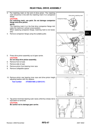
9. Put matching mark on the end of the drive pinion. The matching
mark should be in line with the matching mark A on companion
flange.
CAUTION:
For matching mark, use paint. Do not damage drive pinion.
NOTE:
The matching mark A on the final drive companion flange indi-
cates the maximum vertical runout position.Tool number A: KV40104100 ( — )
B: ST36230000 (J-25840-A)
ModelCircular clip installation position
Right side Left side
R200 (2-pinion) Final drive side
R200V (LSD) Final drive side Side flange side
Tool number A: ST3127S000 (J-25765-A)
SDIA1005E
PDIA1006E
Tool number : KV40104000 ( — )
SDIA1142E
PDIA0629E
Page 12 of 60
RFD-12
FRONT OIL SEAL
Revision: 2006 November2007 350Z
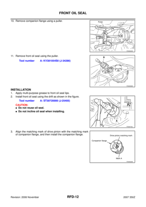
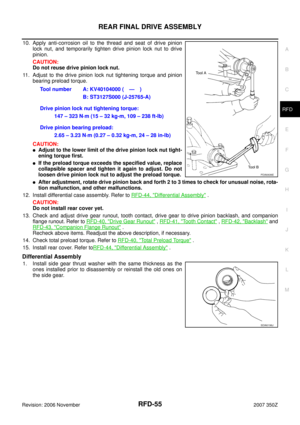
10. Remove companion flange using a puller.
11. Remove front oil seal using the puller.
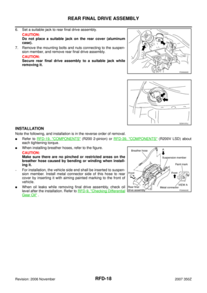
INSTALLATION
1. Apply multi-purpose grease to front oil seal lips.
2. Install front oil seal using the drift as shown in the figure.
CAUTION:
�Do not reuse oil seal.
�Do not incline oil seal when installing.
3. Align the matching mark of drive pinion with the matching mark
of companion flange, and then install the companion flange.
PDIA0630E
Tool number A: KV381054S0 (J-34286)
PDIA0980E
Tool number A: ST30720000 (J-25405)
PDIA0752J
PDIA0629E
Page 13 of 60

FRONT OIL SEAL
RFD-13
C
E
F
G
H
I
J
K
L
MA
B
RFD
Revision: 2006 November2007 350Z
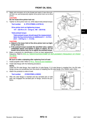
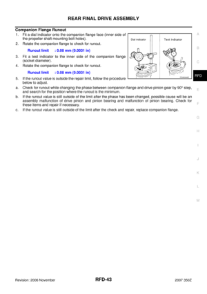
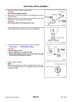
4. Apply anti-corrosion oil to the thread and seat of new drive pin-
ion lock nut, and temporarily tighten drive pinion lock nut to drive
pinion.
CAUTION:
Do not reuse drive pinion lock nut.
5. Tighten to drive pinion lock nut, while adjust total preload torque.
CAUTION:
�Adjust to the lower limit of the drive pinion lock nut tight-
ening torque first.
�If the preload torque exceeds the specified value, replace
collapsible spacer and tighten it again to adjust. Do not
loosen drive pinion lock nut to adjust the preload torque.
6. Make a stamping for identification of front oil seal replacement
frequency. Refer to RFD-10, "
IDENTIFICATION STAMP OF REPLACEMENT FREQUENCY OF FRONT
OIL SEAL" .
CAUTION:
Be sure to make a stamping after replacing front oil seal.
7. Install propeller shaft. Refer to PR-6, "
Removal and Installation" .
8. Install side flange with the following procedure.
NOTE:
Install the RH side flange, then install the LH side flange. If LH side flange is installed first, the RH side
flange comes out sometimes from the shock of installing the RH side flange. [For R200V (with LSD)]
a. Attach the protector to side oil seal.
b. After the side flange is inserted and the serrated part of side
gear has engaged the serrated part of flange, remove the pro-
tector.Tool number A: ST3127S000 (J-25765-A)
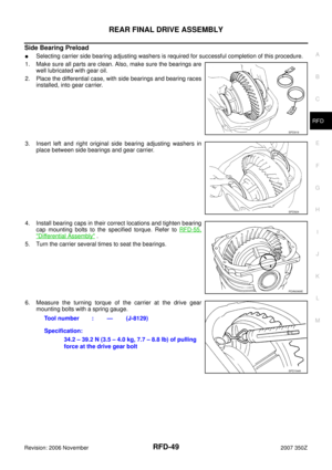
Drive pinion lock nut tightening torque:
147 – 323 N·m (15 – 32 kg-m, 109 – 238 ft-lb)
Total preload torque:
Total preload torque should equal the measurement
taken during removal plus an additional 0.1 – 0.4 N·m
(0.01 – 0.04 kg-m, 1 – 3 in-lb).
Tool number : KV38107900 (J-39352)
PDIA1007E
SDIA0822E
Page 14 of 60
RFD-14
FRONT OIL SEAL
Revision: 2006 November2007 350Z
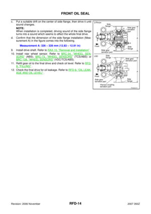
c. Put a suitable drift on the center of side flange, then drive it until
sound changes.
NOTE:
When installation is completed, driving sound of the side flange
turns into a sound which seems to affect the whole final drive.
d. Confirm that the dimension of the side flange installation (Mea-
surement A) in the figure comes into the following.
9. Install drive shaft. Refer to RAX-10, "
Removal and Installation" .
10. Install rear wheel sensor. Refer to BRC-34, "
WHEEL SEN-
SORS" (ABS), BRC-73, "WHEEL SENSORS" (TCS/ABS) or
BRC-128, "
WHEEL SENSORS" (VDC/TCS/ABS).
11. Refill gear oil to the final drive and check oil level. Refer to RFD-
9, "FILLING" .
12. Check the final drive for oil leakage. Refer to RFD-9, "
OIL LEAK-
AGE AND OIL LEVEL" . Measurement A: 326 – 328 mm (12.83 – 12.91 in)
PDIA0631E
Page 15 of 60

SIDE OIL SEAL
RFD-15
C
E
F
G
H
I
J
K
L
MA
B
RFD
Revision: 2006 November2007 350Z
SIDE OIL SEALPFP:33142
Removal and InstallationNDS0000H
REMOVAL
1. Remove rear wheel sensor. Refer to BRC-34, "WHEEL SENSORS" (ABS),BRC-73, "WHEEL SEN-
SORS" (TCS/ABS) or BRC-128, "WHEEL SENSORS" (VDC/TCS/ABS).
2. Remove drive shaft from final drive. Then suspend it by wire etc. Refer to RAX-10, "
Removal and Installa-
tion" .
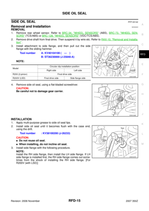
3. Install attachment to side flange, and then pull out the side
flange with the sliding hammer.
NOTE:
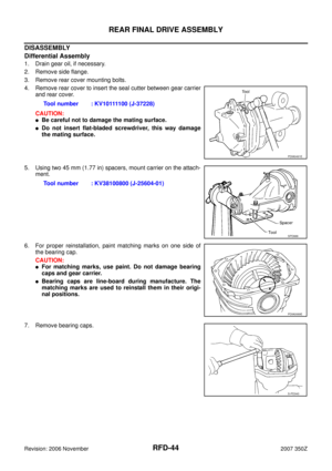
4. Remove side oil seal, using a flat-bladed screwdriver.
CAUTION:
Be careful not to damage gear carrier.
INSTALLATION
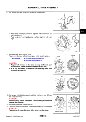
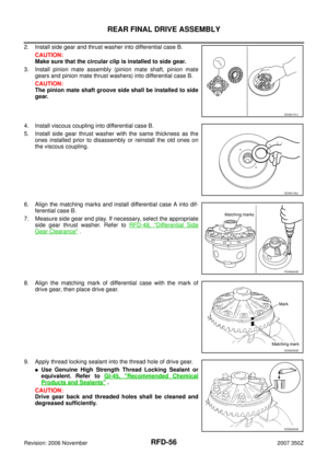
1. Apply multi-purpose grease to side oil seal lips.
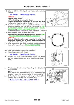
2. Install side oil seal until it becomes flush with the case end,
using the drift.
CAUTION:
�Do not reuse oil seal.
�When installing, do not incline oil seal.
3. Install side flange with the following procedure.
NOTE:
Install the RH side flange, then install the LH side flange. If LH
side flange is installed first, the RH side flange comes out some-
times from the shock of installing the RH side flange. [For
R200V (with LSD)]Tool number A: KV40104100 ( — )
B: ST36230000 (J-25840-A)
ModelCircular clip installation position
Right side Left side
R200 (2-pinion) Final drive side
R200V (LSD) Final drive side Side flange side
SDIA1005E
SDIA1036E
Tool number : KV38100200 (J-26233)
SDIA1037E
Page 16 of 60
RFD-16
SIDE OIL SEAL
Revision: 2006 November2007 350Z
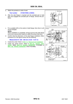
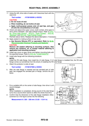
a. Attach the protector to side oil seal.
b. After the side flange is inserted and the serrated part of side
gear has engaged the serrated part of flange, remove the pro-
tector.
c. Put a suitable drift on the center of side flange, then drive it until
sound changes.
NOTE:
When installation is completed, driving sound of the side flange
turns into a sound which seems to affect the whole final drive.
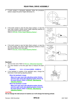
d. Confirm that the dimension of the side flange installation (Mea-
surement A) in the figure comes into the following.
4. Install drive shaft. Refer to RAX-10, "
Removal and Installation" .
5. Install rear wheel sensor. Refer to BRC-34, "
WHEEL SEN-
SORS" (ABS),BRC-73, "WHEEL SENSORS" (TCS/ABS) or
BRC-128, "
WHEEL SENSORS" (VDC/TCS/ABS). Tool number : KV38107900 (J-39352)
SDIA0822E
Measurement A: 326 - 328 mm (12.83 - 12.91 in)
PDIA0631E