Page 46 of 62
MT-46
TRANSMISSION ASSEMBLY
Revision: 2006 November2007 350Z
14. Using the inserter and a press to press fit the main shaft bearing
onto the main shaft.
15. Using the inserter and a press to press fit the reverse main gear
bushing onto the main shaft.
16. Using the inserter and a press to press fit the 3rd gear bushing
onto the counter shaft.
17. Install 3rd-4th coupling sleeve and 3rd-4th shifting inserts into the 3rd-4th synchronizer hub.
CAUTION:
�Do not reuse 3rd-4th coupling sleeve and 3rd-4th synchronizer hub.
�Replace 3rd-4th coupling sleeve and 3rd-4th synchronizer hub as a set.
�Install 3rd-4th coupling sleeve with the thicker flange
faced the front side.
18. Install 3rd-4th spread springs in the 3rd-4th shifting inserts.Tool number : ST30911000 ( — )
PCIB0405E
Tool number : ST30911000 ( — )
PCIB0206E
Tool number : ST30911000 ( — )
PCIB0406E
PCIB1366E
Page 47 of 62
TRANSMISSION ASSEMBLY
MT-47
D
E
F
G
H
I
J
K
L
MA
B
MT
Revision: 2006 November2007 350Z
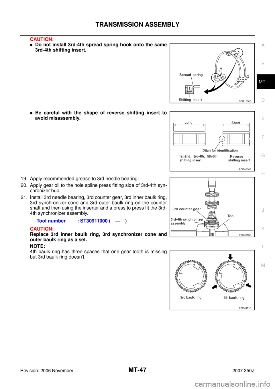
CAUTION:
�Do not install 3rd-4th spread spring hook onto the same
3rd-4th shifting insert.
�Be careful with the shape of reverse shifting insert to
avoid misassembly.
19. Apply recommended grease to 3rd needle bearing.
20. Apply gear oil to the hole spline press fitting side of 3rd-4th syn-
chronizer hub.
21. Install 3rd needle bearing, 3rd counter gear, 3rd inner baulk ring,
3rd synchronizer cone and 3rd outer baulk ring on the counter
shaft and then using the inserter and a press to press fit the 3rd-
4th synchronizer assembly.
CAUTION:
Replace 3rd inner baulk ring, 3rd synchronizer cone and
outer baulk ring as a set.
NOTE:
4th baulk ring has three spaces that one gear tooth is missing
but 3rd baulk ring doesn't.
SCIA1600E
PCIB0608E
Tool number : ST30911000 ( — )
PCIB0615E
PCIB0451E
Page 48 of 62

MT-48
TRANSMISSION ASSEMBLY
Revision: 2006 November2007 350Z
22. Apply recommended grease to 4th needle bearing.
23. Install 4th outer baulk ring, 4th synchronizer cone, 4th inner
baulk ring, 4th needle bearing and 4th counter gear onto the
counter shaft and then using the inserter and a press to press fit
the 4th gear bushing and 4th counter gear thrust washer.
CAUTION:
Replace 4th outer baulk ring, 4th synchronizer cone and 4th
inner baulk ring as a set.
24. Using the inserter and a press to press fit the counter rear bear-
ing inner race onto the counter shaft.
CAUTION:
Replace counter rear bearing inner race, counter rear bear-
ing and counter rear bearing spacer as a set.
25. Using the drift and a press to press fit the main drive gear bear-
ing onto the main drive gear.
26. Select and install a snap ring to the main drive gear bearing so
that the end play comes within the standard value.
CAUTION:
Do not reuse snap ring.
27. Apply recommended grease to main pilot bearing.
28. Install main pilot bearing, pilot bearing spacer and 5th baulk ring
to main drive gear.
29. Install main drive gear assembly, main shaft assembly, and
counter shaft assembly combined in one unit to adapter plate
using brass bar.Tool number : KV40100630 (J-26092)
PCIB0209E
Tool number : ST30032000 (J-26010-01)
PCIB0210E
Tool number : KV32102700 ( — )
PCIB0215E
End play : 0 - 0.10 mm (0 - 0.004 in)
PCIB0484E
PCIB0151E
Page 49 of 62

TRANSMISSION ASSEMBLY
MT-49
D
E
F
G
H
I
J
K
L
MA
B
MT
Revision: 2006 November2007 350Z
30. Install the adapter setting plate to adapter plate and then fixing
in adapter setting plate using a vise.
CAUTION:
Do not directly secure the surface in a vise.
31. Install magnet to adapter plate.
32. Install snap ring to mainshaft bearing.
CAUTION:
Do not reuse snap ring.
33. Install counter rear bearing onto the adapter plate using the drift.
CAUTION:
Replace counter rear bearing inner race, counter rear bear-
ing and counter rear bearing spacer as a set.
34. Apply recommended thread locking sealant to the end of the
bolts (first 3 to 4 threads), screw the bolts into the main shaft
bearing retainer, and tighten it to the specified torque. Refer to
MT-22, "
Case Components" .
�Use Genuine Medium Strength Thread Locking Sealant or
an equivalent. Refer to GI-45, "
RECOMMENDED CHEMI-
CAL PRODUCTS AND SEALANTS" .
CAUTION:
Remove old sealant and oil adhering to threads.
35. Install reverse coupling sleeve and reverse shifting inserts into the reverse synchronizer hub.
CAUTION:
�Do not reuse reverse coupling sleeve and reverse synchronizer hub.
�Replace reverse coupling sleeve and reverse synchronizer hub as a set.Tool number : ST22490000 ( — )
PCIB0254E
SCIA1691E
PCIB1375E
PCIB1238E
Page 50 of 62
MT-50
TRANSMISSION ASSEMBLY
Revision: 2006 November2007 350Z
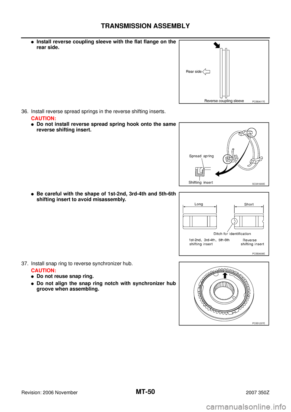
�Install reverse coupling sleeve with the flat flange on the
rear side.
36. Install reverse spread springs in the reverse shifting inserts.
CAUTION:
�Do not install reverse spread spring hook onto the same
reverse shifting insert.
�Be careful with the shape of 1st-2nd, 3rd-4th and 5th-6th
shifting insert to avoid misassembly.
37. Install snap ring to reverse synchronizer hub.
CAUTION:
�Do not reuse snap ring.
�Do not align the snap ring notch with synchronizer hub
groove when assembling.
PCIB0617E
SCIA1600E
PCIB0608E
PCIB1237E
Page 51 of 62
TRANSMISSION ASSEMBLY
MT-51
D
E
F
G
H
I
J
K
L
MA
B
MT
Revision: 2006 November2007 350Z
38. Apply recommended grease to reverse main needle bearing.
39. After installing reverse main gear bushing, reverse main needle
bearing, reverse main gear and reverse baulk ring onto the main
shaft, using the drift and press plate and a press to press fit the
reverse synchronizer assembly.
CAUTION:
When installing, face the side with three ditches to the front
side.
NOTE:
Reverse baulk ring has three spaces that two gear teeth are
missing, and each space has small ditch for identification as
shown in the figure.Tool number A: KV32103300 (J-46529)
Tool number B: ST01530000 ( — )
PCIB0242E
PCIB1367E
PCIB0168E
Page 52 of 62

MT-52
TRANSMISSION ASSEMBLY
Revision: 2006 November2007 350Z
40. Select and install a snap ring so that the end play comes within
the standard value.
CAUTION:
Do not reuse snap ring.
41. After installing counter rear bearing spacer, press and fit reverse
counter gear onto counter shaft with drift and press.
CAUTION:
�Do not reuse reverse counter gear.
�When installing counter rear bearing spacer, identifica-
tion ditch should face to the rear side.
�Replace counter rear bearing inner race, counter rear
bearing and counter rear bearing spacer as a set.
42. Select and install a snap ring so that the end play comes within
the standard value.
CAUTION:
Do not reuse snap ring.
Shift Control Components
1. Install 5th-6th shift fork to the 5th-6th coupling sleeve.
2. Install 5th-6th fork rod (reversal side) to the 5th-6th shift fork.
3. Using a pin punch to tap the retaining pin into the 5th-6th shift
fork.
CAUTION:
Do not reuse retaining pin.End play : 0 - 0.10 mm (0 - 0.004 in)
PCIB0225E
Tool number : ST23860000 ( — )
PCIB0411E
End play : 0 - 0.10 mm (0 - 0.004 in)
PCIB0226E
PCIB0412E
Page 53 of 62

TRANSMISSION ASSEMBLY
MT-53
D
E
F
G
H
I
J
K
L
MA
B
MT
Revision: 2006 November2007 350Z
4. Install 5th-6th fork rod to the adapter plate.
5. Install 5th-6th fork rod bracket to the 5th-6th fork rod.
6. Using a pin punch to tap the retaining pin into the 5th-6th fork
rod bracket.
CAUTION:
Do not reuse retaining pin.
7. Install 5th-6th control lever to the adapter plate and then tighten
mounting bolts to the specified torque. Refer to MT-26, "
Shift
Control Components" .
CAUTION:
Set the projection upward.
8. Apply recommended grease check balls and then install check
balls to the adapter plate.
9. Install reverse shift fork to the reverse coupling sleeve.
10. Install reverse fork rod to the reverse shift fork.
11. Using a pin punch to tap the retaining pin into the reverse shift
fork.
CAUTION:
Do not reuse retaining pin.
12. Apply recommended grease to interlock pin and interlock
plunger.
13. Install interlock pin and interlock plunger to the adapter plate.
PCIB0238E
PCIB0172E
PCIB0148E
SCIA1447E
PCIB0147E