Page 22 of 62
MT-22
TRANSMISSION ASSEMBLY
Revision: 2006 November2007 350Z
Disassembly and AssemblyNCS00011
COMPONENTS
Case Components
1. Breather tube 2. Bracket 3. Filler plug
4. Gasket 5. Front cover oil seal 6. Front cover
7. Front cover gasket 8. Transmission case 9. Drain plug
10. Baffle plate 11. Sliding ball bearing 12. Magnet
13. Dowel pin 14. Bushing 15. Main shaft bearing retainer
16. Adapter plate 17. Oil gutter
A. Seal lip
Refer to GI-11, "
Components" and the followings for the symbols in the figure.
: Apply multi-purpose grease.
: Apply Genuine Silicone RTV or an equivalent. Refer to GI-45, "
Recommended Chemical Products and Sealants" .
: Apply Genuine Medium Strength Thread Locking Sealant or an equivalent. Refer to GI-45, "
Recommended Chemical
Products and Sealants" .
: For the bolt mounting positions, Refer to MT-56, "
Case Components" .
PCIB1917E
Page 23 of 62
TRANSMISSION ASSEMBLY
MT-23
D
E
F
G
H
I
J
K
L
MA
B
MT
Revision: 2006 November2007 350Z
1. Rear extension upper cover 2. Rear extension upper cover gasket 3. Bracket
4. Sliding ball bearing 5. Bushing 6. Plunger
7. Park/Neutral position (PNP) switch 8. Rear extension oil gutter 9. Cap
10. Rear extension 11. Back-up lamp switch 12. Rear oil seal
13. Rear extension dust cover 14. Striking rod oil seal 15. Check ball
16. Check select spring
A. Seal lip
Refer to GI-11, "
Components" and the followings for the symbols in the figure.
: Apply multi-purpose grease.
: Apply Genuine Silicone RTV or an equivalent. Refer to GI-45, "
Recommended Chemical Products and Sealants" .
PCIB1918E
Page 27 of 62
TRANSMISSION ASSEMBLY
MT-27
D
E
F
G
H
I
J
K
L
MA
B
MT
Revision: 2006 November2007 350Z
DISASSEMBLY
Case Components
1. Remove rear extension upper cover mounting bolts.
2. Remove rear extension upper cover and rear extension upper
cover gasket from the rear extension.
1. Control lever housing 2. Check shift pin 3. Control bracket
4. Return spring plug 5. Return spring plunger 6. Return spring
7. Rear extension 8. Boot 9. Control rod
10. Retaining pin
Refer to GI-11, "
Components" and the followings for the symbols in the figure.
: Apply gear oil.
: Apply Genuine Silicone RTV or an equivalent. Refer to GI-45, "
Recommended Chemical Products and Sealants" .
PCIB1919E
SCIA1393E
Page 44 of 62
MT-44
TRANSMISSION ASSEMBLY
Revision: 2006 November2007 350Z
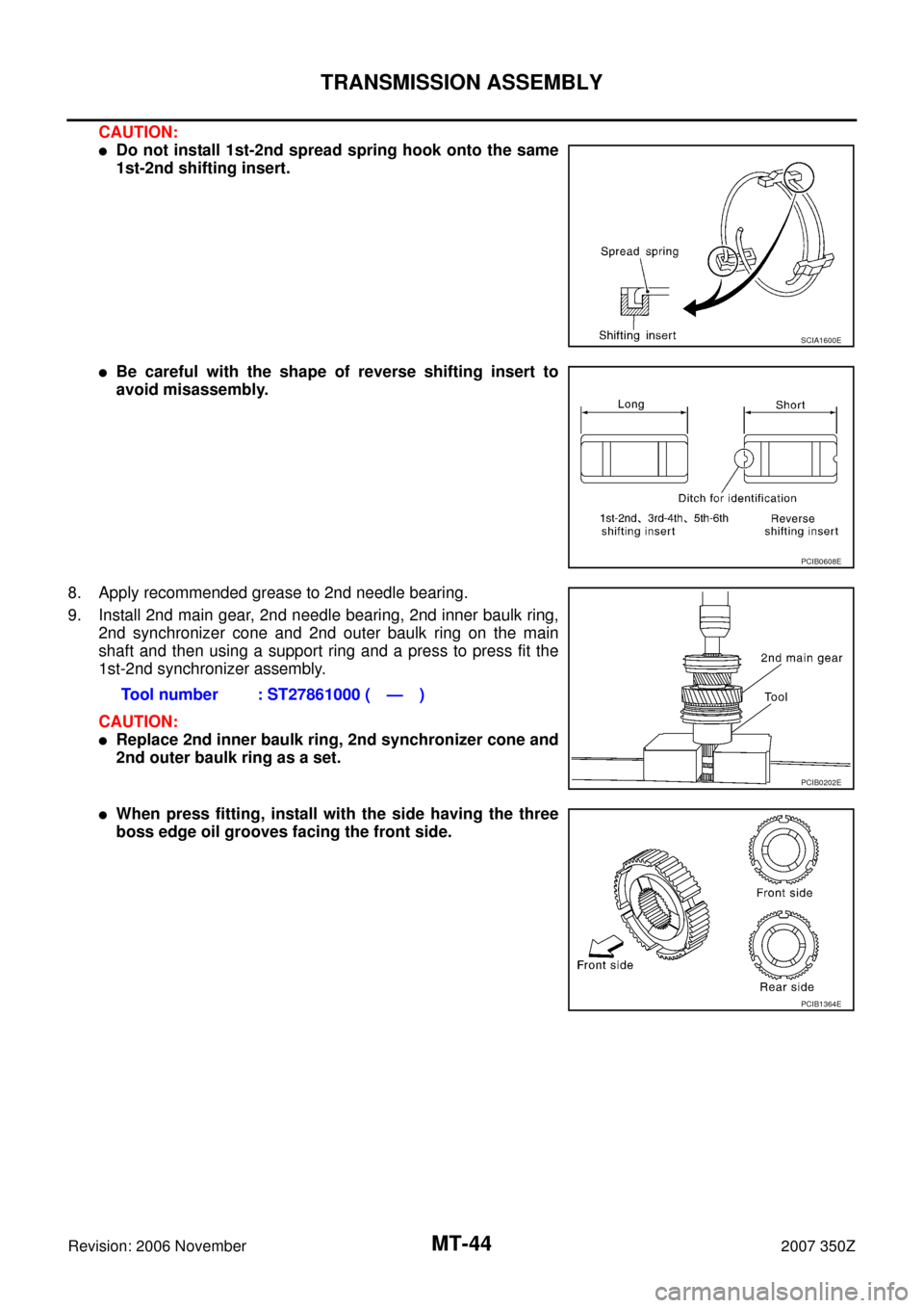
CAUTION:
�Do not install 1st-2nd spread spring hook onto the same
1st-2nd shifting insert.
�Be careful with the shape of reverse shifting insert to
avoid misassembly.
8. Apply recommended grease to 2nd needle bearing.
9. Install 2nd main gear, 2nd needle bearing, 2nd inner baulk ring,
2nd synchronizer cone and 2nd outer baulk ring on the main
shaft and then using a support ring and a press to press fit the
1st-2nd synchronizer assembly.
CAUTION:
�Replace 2nd inner baulk ring, 2nd synchronizer cone and
2nd outer baulk ring as a set.
�When press fitting, install with the side having the three
boss edge oil grooves facing the front side.
SCIA1600E
PCIB0608E
Tool number : ST27861000 ( — )
PCIB0202E
PCIB1364E
Page 47 of 62
TRANSMISSION ASSEMBLY
MT-47
D
E
F
G
H
I
J
K
L
MA
B
MT
Revision: 2006 November2007 350Z
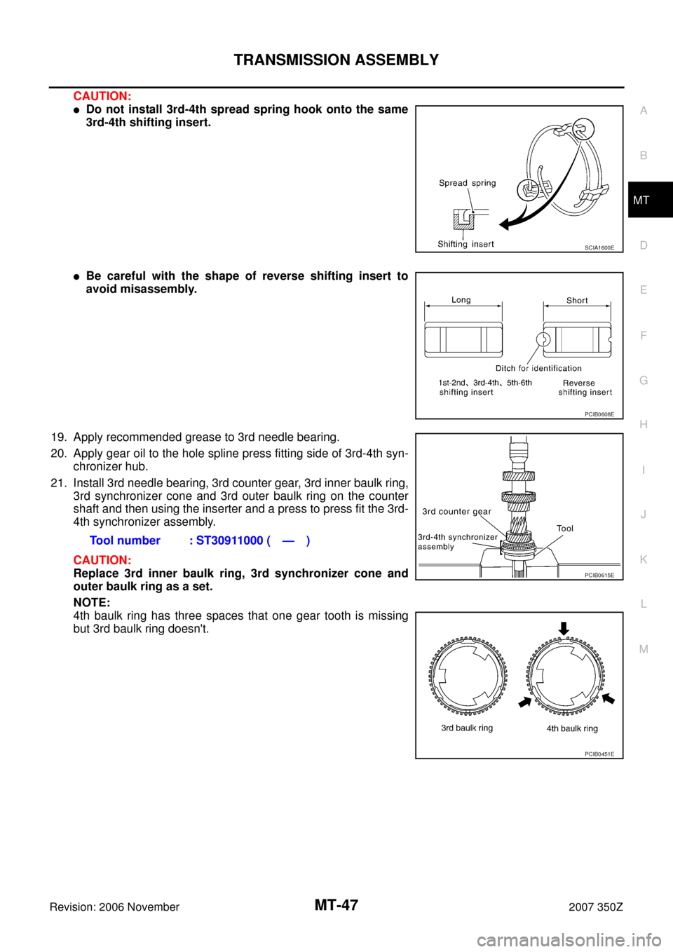
CAUTION:
�Do not install 3rd-4th spread spring hook onto the same
3rd-4th shifting insert.
�Be careful with the shape of reverse shifting insert to
avoid misassembly.
19. Apply recommended grease to 3rd needle bearing.
20. Apply gear oil to the hole spline press fitting side of 3rd-4th syn-
chronizer hub.
21. Install 3rd needle bearing, 3rd counter gear, 3rd inner baulk ring,
3rd synchronizer cone and 3rd outer baulk ring on the counter
shaft and then using the inserter and a press to press fit the 3rd-
4th synchronizer assembly.
CAUTION:
Replace 3rd inner baulk ring, 3rd synchronizer cone and
outer baulk ring as a set.
NOTE:
4th baulk ring has three spaces that one gear tooth is missing
but 3rd baulk ring doesn't.
SCIA1600E
PCIB0608E
Tool number : ST30911000 ( — )
PCIB0615E
PCIB0451E
Page 49 of 62

TRANSMISSION ASSEMBLY
MT-49
D
E
F
G
H
I
J
K
L
MA
B
MT
Revision: 2006 November2007 350Z
30. Install the adapter setting plate to adapter plate and then fixing
in adapter setting plate using a vise.
CAUTION:
Do not directly secure the surface in a vise.
31. Install magnet to adapter plate.
32. Install snap ring to mainshaft bearing.
CAUTION:
Do not reuse snap ring.
33. Install counter rear bearing onto the adapter plate using the drift.
CAUTION:
Replace counter rear bearing inner race, counter rear bear-
ing and counter rear bearing spacer as a set.
34. Apply recommended thread locking sealant to the end of the
bolts (first 3 to 4 threads), screw the bolts into the main shaft
bearing retainer, and tighten it to the specified torque. Refer to
MT-22, "
Case Components" .
�Use Genuine Medium Strength Thread Locking Sealant or
an equivalent. Refer to GI-45, "
RECOMMENDED CHEMI-
CAL PRODUCTS AND SEALANTS" .
CAUTION:
Remove old sealant and oil adhering to threads.
35. Install reverse coupling sleeve and reverse shifting inserts into the reverse synchronizer hub.
CAUTION:
�Do not reuse reverse coupling sleeve and reverse synchronizer hub.
�Replace reverse coupling sleeve and reverse synchronizer hub as a set.Tool number : ST22490000 ( — )
PCIB0254E
SCIA1691E
PCIB1375E
PCIB1238E
Page 54 of 62

MT-54
TRANSMISSION ASSEMBLY
Revision: 2006 November2007 350Z
14. Install 1st-2nd shift fork to the 1st-2nd coupling sleeve.
15. Install 1st-2nd fork rod to the 1st-2nd shift fork.
16. Using a pin punch to tap the retaining pin into the 1st-2nd shift
fork.
CAUTION:
Do not reuse retaining pin.
17. Install 3rd-4th shift fork to the 3rd-4th coupling sleeve.
18. Install 3rd-4th fork rod (reversal side) to the 3rd-4th shift fork.
19. Using a pin punch to tap the retaining pin into the 3rd-4th shift
fork (reversal side).
CAUTION:
Do not reuse retaining pin.
20. Apply recommended grease to interlock pin and check balls.
21. Install interlock pin and check balls to the adapter plate.
22. Install 3rd-4th fork rod to the adapter plate.
23. Install 3rd-4th fork rod bracket to the 3rd-4th fork rod.
24. Using a pin punch to tap the retaining pin into the 3rd-4th fork
rod bracket.
CAUTION:
Do not reuse retaining pin.
25. Apply recommended grease to check ball and then install check
ball and check ball spring into adapter plate.
26. Apply recommended sealant to threads of check ball plugs, and
tighten check ball plugs to the specified torque. Refer to MT-26,
"Shift Control Components" .
�Use Genuine Silicone RTV or an equivalent. Refer to GI-
45, "RECOMMENDED CHEMICAL PRODUCTS AND SEAL-
ANTS" .
CAUTION:
Remove old sealant and oil adhering to threads.
PCIB0602E
PCIB0601E
PCIB0146E
PCIB0145E
PCIB0144E
Page 55 of 62

TRANSMISSION ASSEMBLY
MT-55
D
E
F
G
H
I
J
K
L
MA
B
MT
Revision: 2006 November2007 350Z
27. Install 3rd-4th control lever to the adapter plate, and then tighten
mounting bolts to the specified torque. Refer to MT-26, "
Shift
Control Components" .
CAUTION:
�Make sure the top and bottom are oriented correctly.
�Do not drop shifter cap.
28. Apply recommended grease to check ball and then install check
balls and check ball springs into adapter plate.
29. Apply recommended sealant to threads of check ball plugs, and
tighten check ball plugs to the specified torque. Refer to MT-26,
"Shift Control Components" .
�Use Genuine Silicone RTV or an equivalent. Refer to GI-
45, "RECOMMENDED CHEMICAL PRODUCTS AND SEAL-
ANTS" .
CAUTION:
Remove old sealant and oil adhering to threads.
30. Install striking rod to the adapter plate.
31. Install striking lever to the striking rod.
32. Using a pin punch to tap the retaining pin into the striking lever.
CAUTION:
Do not reuse retaining pin.
33. Install baffle plate to the adapter plate, and then tighten mount-
ing bolts to the specified torque.
PCIB1352E
PCIB0143E
PCIB0414E
PCIB0154E