Page 33 of 76
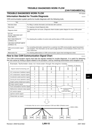
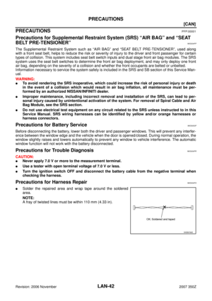
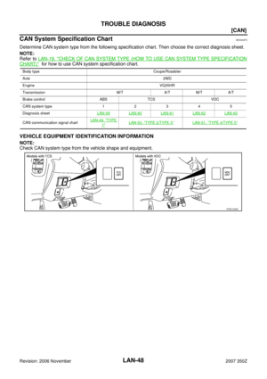
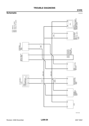
TROUBLE DIAGNOSES WORK FLOW
LAN-33
[CAN FUNDAMENTAL]
C
D
E
F
G
H
I
J
L
MA
B
LAN
Revision: 2006 November2007 350Z
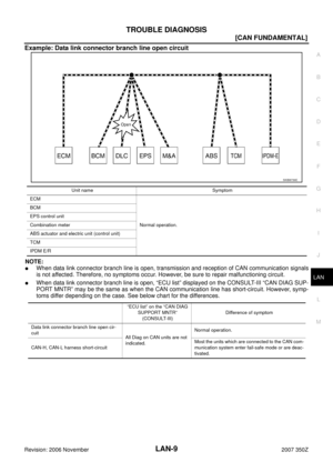
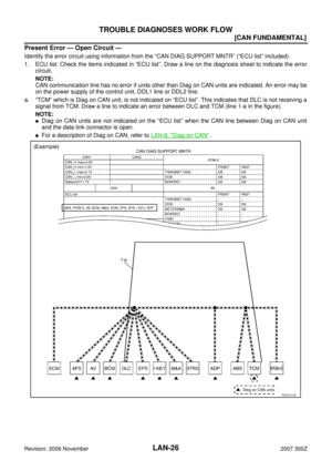
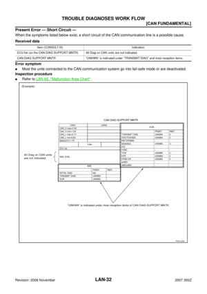
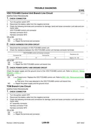
Past Error — Open Circuit —
Review CAN communication signal chart based on information received from the interview with the customer
and on past error information from SELF-DIAG RESULTS and CAN DIAG SUPPORT MNTR.
1. SELF-DIAG RESULTS: Inspect the control units indicating “U1000” or “U1001” on SELF-DIAG RESULTS.
PKID1221E
Page 34 of 76
![NISSAN 350Z 2007 Z33 LAN System Workshop Manual LAN-34
[CAN FUNDAMENTAL]
TROUBLE DIAGNOSES WORK FLOW
Revision: 2006 November2007 350Z
2. CAN DIAG SUPPORT MNTR (with PAST): Check the CAN DIAG SUPPORT MNTR (with PAST) of units
indicating “U1000”](/manual-img/5/774/w960_774-33.png "NISSAN 350Z 2007 Z33 LAN System Workshop Manual LAN-34
[CAN FUNDAMENTAL]
TROUBLE DIAGNOSES WORK FLOW
Revision: 2006 November2007 350Z
2. CAN DIAG SUPPORT MNTR (with PAST): Check the CAN DIAG SUPPORT MNTR (with PAST) of units
indicating “U1000”")
LAN-34
[CAN FUNDAMENTAL]
TROUBLE DIAGNOSES WORK FLOW
Revision: 2006 November2007 350Z
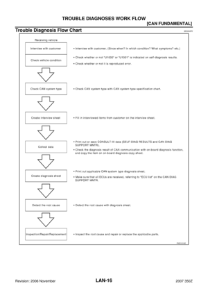
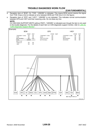
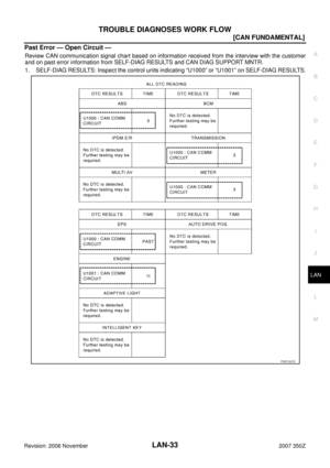
2. CAN DIAG SUPPORT MNTR (with PAST): Check the CAN DIAG SUPPORT MNTR (with PAST) of units
indicating “U1000” or “U1001” on SELF-DIAG RESULTS. Draw a line on the diagnosis sheet to indicate
the possible error circuit.
NOTE:
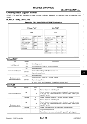
For the details of each indication on CAN DIAG SUPPORT MNTR, refer to LAN-44, "
CAN Diagnostic Sup-
port Monitor" .
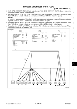
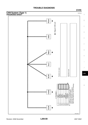
a. Reception item of “ECM”: “VDC/TCS/ABS”, “3” is indicated in the “PAST”. This means ECM could not
receive the signal from ABS in the past. Draw a line between ECM and ABS (line 2-a in the figure).
b. Reception item of “M&A”: “VDC/TCS/ABS”, “3” is indicated in the “PAST”. This means M&A could not
receive the signal from ABS in the past. Draw a line between M&A and ABS (line 2-b in the figure).
c. Reception item of “TCM”: “VDC/TCS/ABS”, “3” is indicated in the “PAST”. This means TCM could not
receive the signal from ABS in the past. Draw a line between TCM and ABS (line 2-c in the figure).
PKID1222E
Page 35 of 76
TROUBLE DIAGNOSES WORK FLOW
LAN-35
[CAN FUNDAMENTAL]
C
D
E
F
G
H
I
J
L
MA
B
LAN
Revision: 2006 November2007 350Z
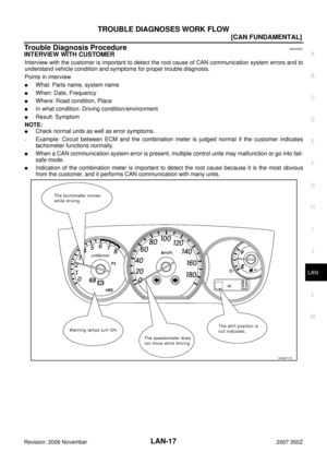
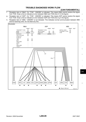
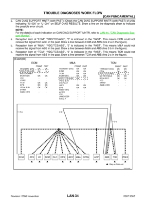
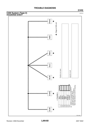
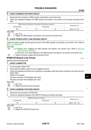
3. CAN DIAG SUPPORT MNTR (without PAST): Check the CAN DIAG SUPPORT MNTR (without PAST) of
units indicating “U1000” or “U1001” on SELF-DIAG RESULTS. Draw a line on the diagnosis sheet to indi-
cate the possible error circuit.
NOTE:
�While an error occurred in the past according to SELF-DIAG RESULTS, it is unclear which signal is not
received. Assume that errors were detected from all reception items.
�Draw a single line among the unit and all reception items. (Work flow differs from CAN DIAG SUPPORT
MNTR (with PAST).)
a. Reception item of “EPS”: Assume that the unit could not receive the signals from ECM, ABS, and M&A.
Draw a line among EPS, ECM, ABS, and M&A (line 3-a in the figure).
b. Reception item of “ABS”: Assume that the unit could not receive the signal from ECM. Draw a line
between ABS and ECM (line 3-b in the figure).
PKID1223E
Page 36 of 76
LAN-36
[CAN FUNDAMENTAL]
TROUBLE DIAGNOSES WORK FLOW
Revision: 2006 November2007 350Z
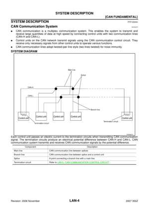
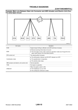
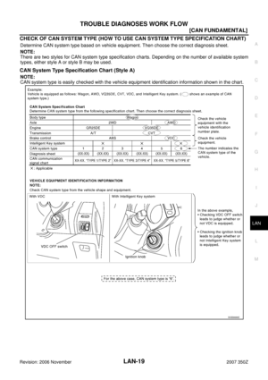
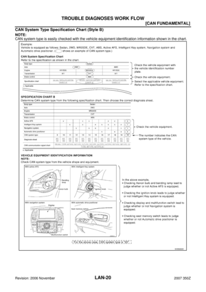
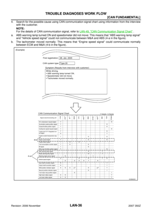
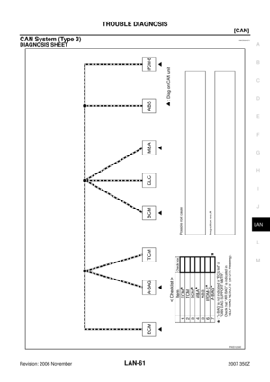
4. Search for the possible cause using CAN communication signal chart using information from the interview
with the customer.
NOTE:
For the details of CAN communication signal, refer to LAN-49, "
CAN Communication Signal Chart" .
a. ABS warning lamp turned ON and speedometer did not move: This means that “ABS warning lamp signal”
and “Vehicle speed signal” could not communicate between M&A and ABS (4-a in the figure).
b. The tachometer moved normally: This means that “Engine speed signal” could communicate normally
between ECM and M&A (4-b in the figure).
SKIB8895E
Page 37 of 76
TROUBLE DIAGNOSES WORK FLOW
LAN-37
[CAN FUNDAMENTAL]
C
D
E
F
G
H
I
J
L
MA
B
LAN
Revision: 2006 November2007 350Z
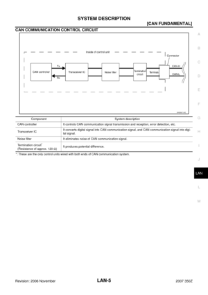
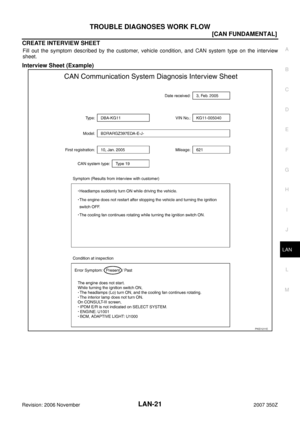
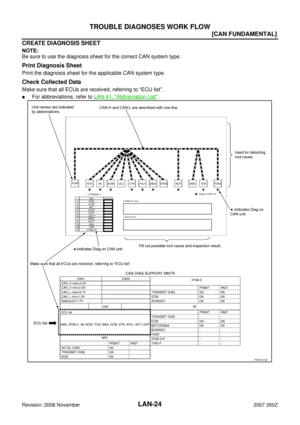
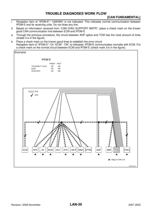
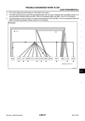
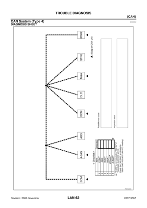
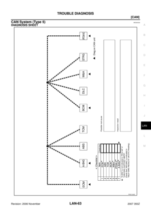
5. Fill out the diagnosis sheet based on information from step 4.
a. The ABS warning lamp turned ON and speedometer did not move: Assume that a possible cause is no
communication between M&A and ABS. Draw a line between M&A and ABS. (Line 5-a in the figure).
b. The tachometer moved normally: Put check marks between ECM and M&A. The circuit between ECM and
M&A is functioning properly (check marks 5-b in the figure).
SKIB8735E
Page 38 of 76
LAN-38
[CAN FUNDAMENTAL]
TROUBLE DIAGNOSES WORK FLOW
Revision: 2006 November2007 350Z
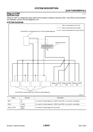
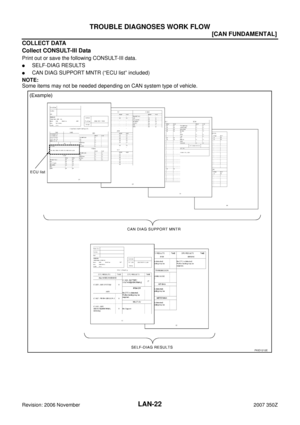
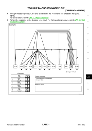
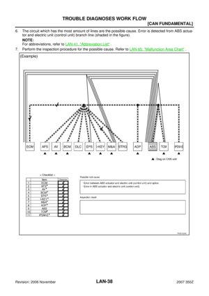
6. The circuit which has the most amount of lines are the possible cause. Error is detected from ABS actua-
tor and electric unit (control unit) branch line (shaded in the figure).
NOTE:
For abbreviations, refer to LAN-41, "
Abbreviation List" .
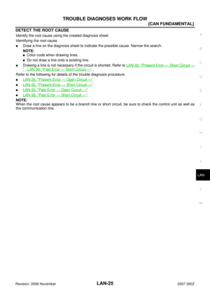
7. Perform the inspection procedure for the possible cause. Refer to LAN-65, "
Malfunction Area Chart" .
PKID1224E
Page 39 of 76
TROUBLE DIAGNOSES WORK FLOW
LAN-39
[CAN FUNDAMENTAL]
C
D
E
F
G
H
I
J
L
MA
B
LAN
Revision: 2006 November2007 350Z
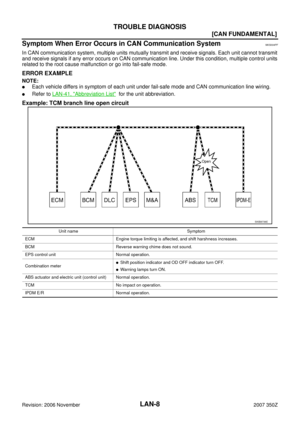
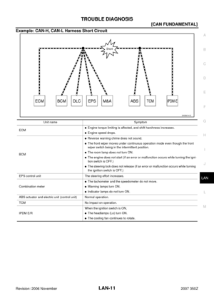
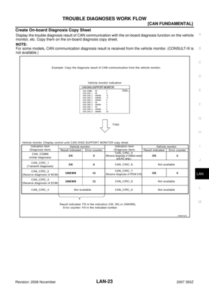
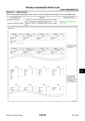
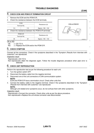
Past Error — Short Circuit —
When the symptoms listed below exist, a short circuit of the CAN communication line is a possible cause.
Item (CONSULT-III) Indication Inspection procedure
SELF-DIAG RESULTS “U1000” and “U1001” is indicated in the past for most units.
Refer to LAN-65, "
Malfunction
Area Chart" .
CAN DIAG SUPPORT MNTROnly on CAN DIAG SUPPORT MNTR (with PAST), “1 - 39” is
indicated on “PAST” of “TRANSMIT DIAG” and the reception
item.
PKID1225E
Page 40 of 76
![NISSAN 350Z 2007 Z33 LAN System Workshop Manual LAN-40
[CAN]
INDEX FOR DTC
Revision: 2006 November2007 350Z
[CAN]INDEX FOR DTCPFP:00004
DTC No. IndexNKS004PM
DTCSelf-diagnosis item
(CONSULT-III indication)DTC detection condition Inspection
U1000 C](/manual-img/5/774/w960_774-39.png "NISSAN 350Z 2007 Z33 LAN System Workshop Manual LAN-40
[CAN]
INDEX FOR DTC
Revision: 2006 November2007 350Z
[CAN]INDEX FOR DTCPFP:00004
DTC No. IndexNKS004PM
DTCSelf-diagnosis item
(CONSULT-III indication)DTC detection condition Inspection
U1000 C")
LAN-40
[CAN]
INDEX FOR DTC
Revision: 2006 November2007 350Z
[CAN]INDEX FOR DTCPFP:00004
DTC No. IndexNKS004PM
DTCSelf-diagnosis item
(CONSULT-III indication)DTC detection condition Inspection
U1000 CAN COMM CIRCUITWhen ECM is not transmitting or receiving CAN
communication signal of OBD (emission-related
diagnosis) for 2 seconds or more.
Refer to LAN-41, "
HOW
TO USE THIS SEC-
TION" . When a control unit (except for ECM) is not
transmitting or receiving CAN communication
signal for 2 seconds or more.
U1001 CAN COMM CIRCUITWhen ECM is not transmitting or receiving CAN
communication signal other than OBD (emis-
sion-related diagnosis) for 2 seconds or more.
U1002 SYSTEM COMMWhen a control unit is not transmitting or receiv-
ing CAN communication signal for 2 seconds or
less.Start the inspection.
Refer to the applicable
section of the indicated
control unit.
U1010 CONTROL UNIT [CAN]When an error is detected during the initial diag-
nosis for CAN controller of each control unit.Replace the control unit
indicating “U1010”.


![NISSAN 350Z 2007 Z33 LAN System Workshop Manual TROUBLE DIAGNOSES WORK FLOW
LAN-33
[CAN FUNDAMENTAL]
C
D
E
F
G
H
I
J
L
MA
B
LAN
Revision: 2006 November2007 350Z
Past Error — Open Circuit —
Review CAN communication signal chart based on informat](/manual-img/5/774/w960_774-32.png "NISSAN 350Z 2007 Z33 LAN System Workshop Manual TROUBLE DIAGNOSES WORK FLOW
LAN-33
[CAN FUNDAMENTAL]
C
D
E
F
G
H
I
J
L
MA
B
LAN
Revision: 2006 November2007 350Z
Past Error — Open Circuit —
Review CAN communication signal chart based on informat")
![NISSAN 350Z 2007 Z33 LAN System Workshop Manual TROUBLE DIAGNOSES WORK FLOW
LAN-35
[CAN FUNDAMENTAL]
C
D
E
F
G
H
I
J
L
MA
B
LAN
Revision: 2006 November2007 350Z
3. CAN DIAG SUPPORT MNTR (without PAST): Check the CAN DIAG SUPPORT MNTR (without PAST)](/manual-img/5/774/w960_774-34.png "NISSAN 350Z 2007 Z33 LAN System Workshop Manual TROUBLE DIAGNOSES WORK FLOW
LAN-35
[CAN FUNDAMENTAL]
C
D
E
F
G
H
I
J
L
MA
B
LAN
Revision: 2006 November2007 350Z
3. CAN DIAG SUPPORT MNTR (without PAST): Check the CAN DIAG SUPPORT MNTR (without PAST)")
![NISSAN 350Z 2007 Z33 LAN System Workshop Manual LAN-36
[CAN FUNDAMENTAL]
TROUBLE DIAGNOSES WORK FLOW
Revision: 2006 November2007 350Z
4. Search for the possible cause using CAN communication signal chart using information from the interview
with th](/manual-img/5/774/w960_774-35.png "NISSAN 350Z 2007 Z33 LAN System Workshop Manual LAN-36
[CAN FUNDAMENTAL]
TROUBLE DIAGNOSES WORK FLOW
Revision: 2006 November2007 350Z
4. Search for the possible cause using CAN communication signal chart using information from the interview
with th")
![NISSAN 350Z 2007 Z33 LAN System Workshop Manual TROUBLE DIAGNOSES WORK FLOW
LAN-37
[CAN FUNDAMENTAL]
C
D
E
F
G
H
I
J
L
MA
B
LAN
Revision: 2006 November2007 350Z
5. Fill out the diagnosis sheet based on information from step 4.
a. The ABS warning la](/manual-img/5/774/w960_774-36.png "NISSAN 350Z 2007 Z33 LAN System Workshop Manual TROUBLE DIAGNOSES WORK FLOW
LAN-37
[CAN FUNDAMENTAL]
C
D
E
F
G
H
I
J
L
MA
B
LAN
Revision: 2006 November2007 350Z
5. Fill out the diagnosis sheet based on information from step 4.
a. The ABS warning la")
![NISSAN 350Z 2007 Z33 LAN System Workshop Manual LAN-38
[CAN FUNDAMENTAL]
TROUBLE DIAGNOSES WORK FLOW
Revision: 2006 November2007 350Z
6. The circuit which has the most amount of lines are the possible cause. Error is detected from ABS actua-
tor an](/manual-img/5/774/w960_774-37.png "NISSAN 350Z 2007 Z33 LAN System Workshop Manual LAN-38
[CAN FUNDAMENTAL]
TROUBLE DIAGNOSES WORK FLOW
Revision: 2006 November2007 350Z
6. The circuit which has the most amount of lines are the possible cause. Error is detected from ABS actua-
tor an")
![NISSAN 350Z 2007 Z33 LAN System Workshop Manual TROUBLE DIAGNOSES WORK FLOW
LAN-39
[CAN FUNDAMENTAL]
C
D
E
F
G
H
I
J
L
MA
B
LAN
Revision: 2006 November2007 350Z
Past Error — Short Circuit —
When the symptoms listed below exist, a short circuit](/manual-img/5/774/w960_774-38.png "NISSAN 350Z 2007 Z33 LAN System Workshop Manual TROUBLE DIAGNOSES WORK FLOW
LAN-39
[CAN FUNDAMENTAL]
C
D
E
F
G
H
I
J
L
MA
B
LAN
Revision: 2006 November2007 350Z
Past Error — Short Circuit —
When the symptoms listed below exist, a short circuit")