Page 65 of 76
![NISSAN 350Z 2007 Z33 LAN System Workshop Manual TROUBLE DIAGNOSIS
LAN-65
[CAN]
C
D
E
F
G
H
I
J
L
MA
B
LAN
Revision: 2006 November2007 350Z
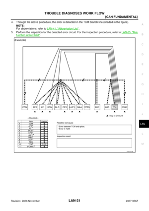
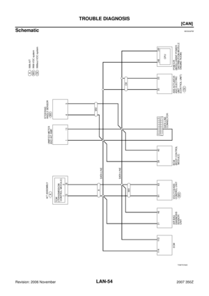
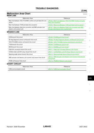
Malfunction Area ChartNKS004RL
MAIN LINE
BRANCH LINE
SHORT CIRCUIT
Malfunction Area Reference
Main line betwe](/manual-img/5/774/w960_774-64.png "NISSAN 350Z 2007 Z33 LAN System Workshop Manual TROUBLE DIAGNOSIS
LAN-65
[CAN]
C
D
E
F
G
H
I
J
L
MA
B
LAN
Revision: 2006 November2007 350Z
Malfunction Area ChartNKS004RL
MAIN LINE
BRANCH LINE
SHORT CIRCUIT
Malfunction Area Reference
Main line betwe")
TROUBLE DIAGNOSIS
LAN-65
[CAN]
C
D
E
F
G
H
I
J
L
MA
B
LAN
Revision: 2006 November2007 350Z
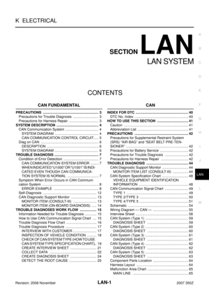
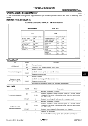
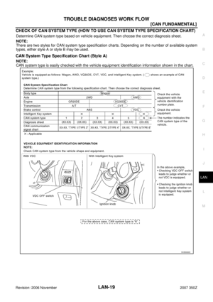
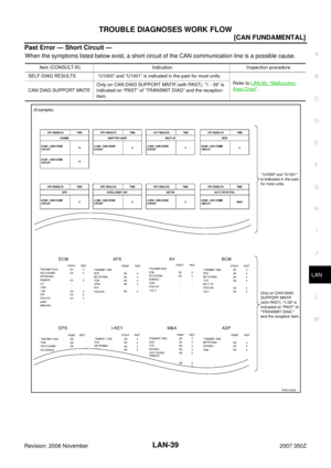
Malfunction Area ChartNKS004RL
MAIN LINE
BRANCH LINE
SHORT CIRCUIT
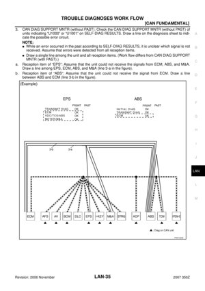
Malfunction Area Reference
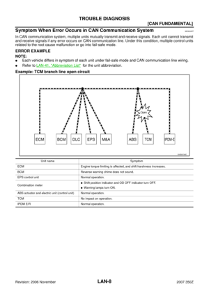
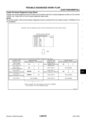
Main line between VDC/TCS/ABS control unit and data link con-
nectorLAN-66, "
Main Line Between VDC/TCS/ABS Control Unit and
Data Link Connector"
Main line between TCM and data link connectorLAN-66, "Main Line Between TCM and Data Link Connector"
Main line between data link connector and ABS actuator and
electric unit (control unit)LAN-67, "Main Line Between Data Link Connector and ABS
Actuator and Electric Unit (Control Unit)"
Malfunction Area Reference
ECM branch line circuitLAN-68, "
ECM Branch Line Circuit"
Air bag diagnosis sensor unit branch line circuitLAN-68, "Air Bag Diagnosis Sensor Unit Branch Line Circuit"
VDC/TCS/ABS control unit branch line circuitLAN-69, "VDC/TCS/ABS Control Unit Branch Line Circuit"
TCM branch line circuitLAN-69, "TCM Branch Line Circuit"
BCM branch line circuitLAN-70, "BCM Branch Line Circuit"
Data link connector branch line circuitLAN-71, "Data Link Connector Branch Line Circuit"
Unified meter and A/C amp. branch line circuitLAN-71, "Unified Meter and A/C Amp. Branch Line Circuit"
Steering angle sensor branch line circuitLAN-72, "Steering Angle Sensor Branch Line Circuit"
ABS actuator and electric unit (control unit) branch line circuitLAN-72, "ABS Actuator and Electric Unit (Control Unit) Branch
Line Circuit"
IPDM E/R branch line circuitLAN-73, "IPDM E/R Branch Line Circuit"
Malfunction Area Reference
CAN communication circuitLAN-74, "
CAN Communication Circuit"
Page 66 of 76
![NISSAN 350Z 2007 Z33 LAN System Workshop Manual LAN-66
[CAN]
TROUBLE DIAGNOSIS
Revision: 2006 November2007 350Z
Main Line Between VDC/TCS/ABS Control Unit and Data Link ConnectorNKS0054K
INSPECTION PROCEDURE
1. CHECK HARNESS CONTINUITY (OPEN CIRCUI](/manual-img/5/774/w960_774-65.png "NISSAN 350Z 2007 Z33 LAN System Workshop Manual LAN-66
[CAN]
TROUBLE DIAGNOSIS
Revision: 2006 November2007 350Z
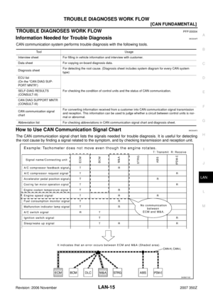
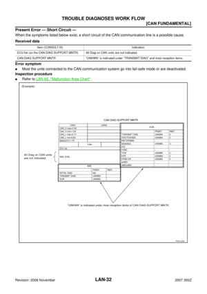
Main Line Between VDC/TCS/ABS Control Unit and Data Link ConnectorNKS0054K
INSPECTION PROCEDURE
1. CHECK HARNESS CONTINUITY (OPEN CIRCUI")
LAN-66
[CAN]
TROUBLE DIAGNOSIS
Revision: 2006 November2007 350Z
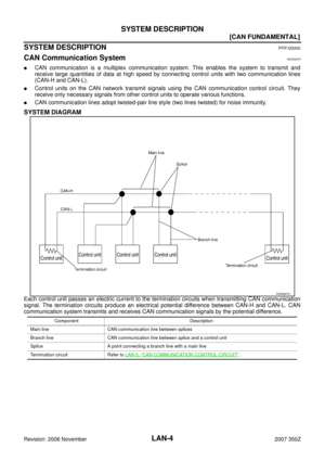
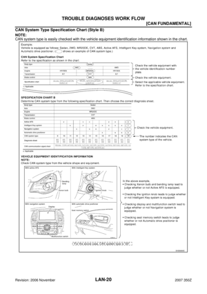
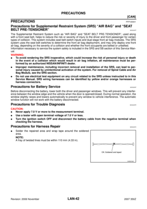
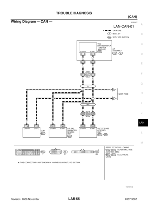
Main Line Between VDC/TCS/ABS Control Unit and Data Link ConnectorNKS0054K
INSPECTION PROCEDURE
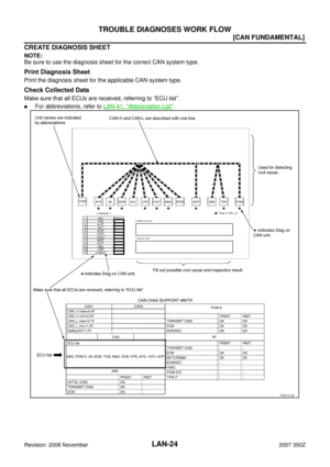
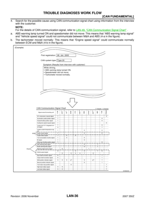
1. CHECK HARNESS CONTINUITY (OPEN CIRCUIT)
1. Turn the ignition switch OFF.
2. Disconnect the battery cable from the negative terminal.
3. Disconnect the following harness connectors.
–ECM harness connector
–Harness connectors B101 and M73
4. Check the continuity between the Harness connector M73 and the data link connector.
OK or NG
OK >>�Present error: Check the following items again.
–Decision of CAN system type.
–Not received CONSULT-III data [SELF-DIAG RESULTS, CAN DIAG SUPPORT MNTR (“ECU
list” included)].
–Procedure for detecting root cause.
�Past error: Error was detected in the main line between the VDC/TCS/ABS control unit and the
data link connector.
NG >> Repair the main line between the harness connector M73 and the data link connector.
Main Line Between TCM and Data Link ConnectorNKS0054L
INSPECTION PROCEDURE
1. CHECK HARNESS CONTINUITY (OPEN CIRCUIT)
1. Turn the ignition switch OFF.
2. Disconnect the battery cable from the negative terminal.
3. Disconnect the following harness connectors.
–ECM harness connector
–Harness connectors F102 and M72
4. Check the continuity between the Harness connector M72 and the data link connector.
OK or NG
OK >>�Present error: Check the following items again.
–Decision of CAN system type.
–Not received CONSULT-III data [SELF-DIAG RESULTS, CAN DIAG SUPPORT MNTR (“ECU
list” included)].
–Procedure for detecting root cause.
�Past error: Error was detected in the main line between the TCM and the data link connector.
NG >> Repair the main line between the harness connector M72 and the data link connector.
Harness connector Data link connector
Continuity
Connector No. Terminal No. Connector No. Terminal No.
M734M
M86Yes
5M 14 Yes
Harness connector Data link connector
Continuity
Connector No. Terminal No. Connector No. Terminal No.
M7225H
M86Yes
24H 14 Yes
Page 67 of 76
![NISSAN 350Z 2007 Z33 LAN System Workshop Manual TROUBLE DIAGNOSIS
LAN-67
[CAN]
C
D
E
F
G
H
I
J
L
MA
B
LAN
Revision: 2006 November2007 350Z
Main Line Between Data Link Connector and ABS Actuator and Electric Unit
(Control Unit)
NKS0054M
INSPECTION](/manual-img/5/774/w960_774-66.png "NISSAN 350Z 2007 Z33 LAN System Workshop Manual TROUBLE DIAGNOSIS
LAN-67
[CAN]
C
D
E
F
G
H
I
J
L
MA
B
LAN
Revision: 2006 November2007 350Z
Main Line Between Data Link Connector and ABS Actuator and Electric Unit
(Control Unit)
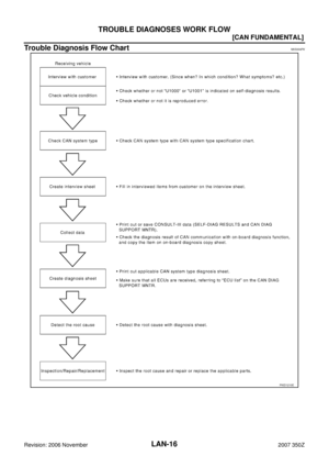
NKS0054M
INSPECTION")
TROUBLE DIAGNOSIS
LAN-67
[CAN]
C
D
E
F
G
H
I
J
L
MA
B
LAN
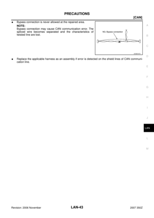
Revision: 2006 November2007 350Z
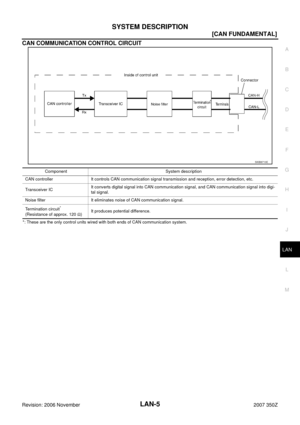
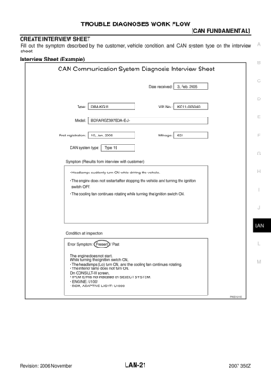
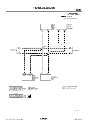
Main Line Between Data Link Connector and ABS Actuator and Electric Unit
(Control Unit)
NKS0054M
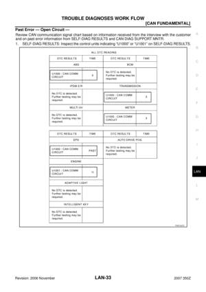
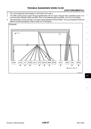
INSPECTION PROCEDURE
1. CHECK CONNECTOR
1. Turn the ignition switch OFF.
2. Disconnect the battery cable from the negative terminal.
3. Check the following terminals and connectors for damage, bend and loose connection (connector side
and harness side).
–Harness connector M15
–Harness connector E108
OK or NG
OK >> GO TO 2.
NG >> Repair the terminal and connector.
2. CHECK HARNESS CONTINUITY (OPEN CIRCUIT)
1. Disconnect the harness connectors M15 and E108.
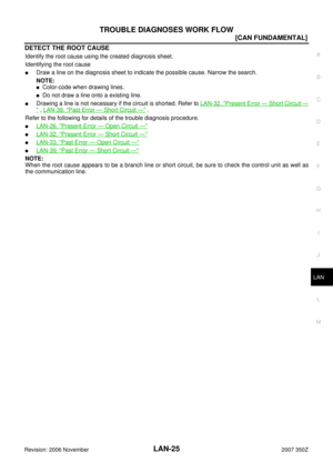
2. Check the continuity between the data link connector and the harness connector.
OK or NG
OK >> GO TO 3.
NG >> Repair the main line between the data link connector and the harness connector M15.
3. CHECK HARNESS CONTINUITY (OPEN CIRCUIT)
1. Disconnect the connector of ABS actuator and electric unit (control unit).
2. Check the continuity between the harness connector and the ABS actuator and electric unit (control unit)
harness connector.
OK or NG
OK >>�Present error: Check the following items again.
–Decision of CAN system type.
–Not received CONSULT-III data [SELF-DIAG RESULTS, CAN DIAG SUPPORT MNTR (“ECU
list” included)].
–Procedure for detecting root cause.
�Past error: Error was detected in the main line between the data link connector and the ABS
actuator and electric unit (control unit).
NG >> Replace the main line between the harness connector E108 and the ABS actuator and electric
unit (control unit).
Data link connector Harness connector
Continuity
Connector No. Terminal No. Connector No. Terminal No.
M86
M152G Yes
14 7G Yes
Harness connectorABS actuator and electric unit (control unit)
harness connector
Continuity
Connector No. Terminal No. Connector No. Terminal No.
E1082G
E5120 Yes
7G 23 Yes
Page 68 of 76
![NISSAN 350Z 2007 Z33 LAN System Workshop Manual LAN-68
[CAN]
TROUBLE DIAGNOSIS
Revision: 2006 November2007 350Z
ECM Branch Line CircuitNKS0054N
INSPECTION PROCEDURE
1. CHECK CONNECTOR
1. Turn the ignition switch OFF.
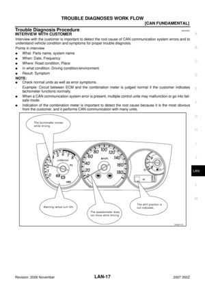
2. Disconnect the battery cable](/manual-img/5/774/w960_774-67.png "NISSAN 350Z 2007 Z33 LAN System Workshop Manual LAN-68
[CAN]
TROUBLE DIAGNOSIS
Revision: 2006 November2007 350Z
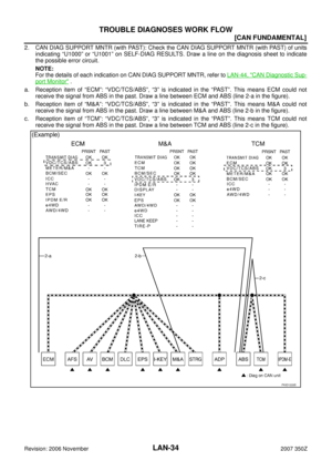
ECM Branch Line CircuitNKS0054N
INSPECTION PROCEDURE
1. CHECK CONNECTOR
1. Turn the ignition switch OFF.
2. Disconnect the battery cable")
LAN-68
[CAN]
TROUBLE DIAGNOSIS
Revision: 2006 November2007 350Z
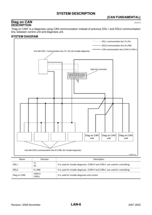
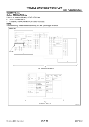
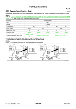
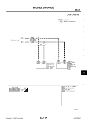
ECM Branch Line CircuitNKS0054N
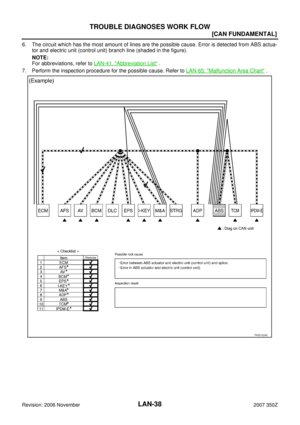
INSPECTION PROCEDURE
1. CHECK CONNECTOR
1. Turn the ignition switch OFF.
2. Disconnect the battery cable from the negative terminal.
3. Check the terminals and connectors of the ECM for damage, bend and loose connection (unit side and
connector side).
OK or NG
OK >> GO TO 2.
NG >> Repair the terminal and connector.
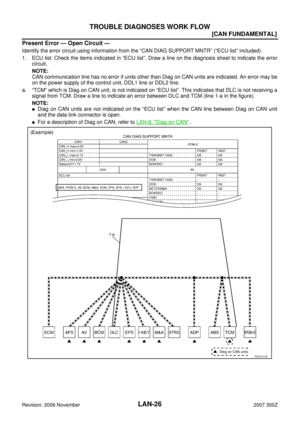
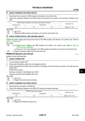
2. CHECK HARNESS FOR OPEN CIRCUIT
1. Disconnect the connector of ECM.
2. Check the resistance between the ECM harness connector terminals.
OK or NG
OK >> GO TO 3.
NG >> Repair the ECM branch line.
3. CHECK POWER SUPPLY AND GROUND CIRCUIT
Check the power supply and the ground circuit of the ECM. Refer to EC-142, "
POWER SUPPLY AND
GROUND CIRCUIT" .
OK or NG
OK >>�Present error: Replace the ECM. Refer to EC-76, "Procedure After Replacing ECM" .
�Past error: Error was detected in the ECM branch line.
NG >> Repair the power supply and the ground circuit.
Air Bag Diagnosis Sensor Unit Branch Line CircuitNKS0054O
INSPECTION PROCEDURE
1. CHECK AIR BAG DIAGNOSIS SENSOR UNIT
Check the air bag diagnosis sensor unit. Refer to SRS-9, "
TROUBLE DIAGNOSIS" .
OK or NG
OK >> Replace the main harness.
NG >> Replace parts whose air bag system has a malfunction.
ECM harness connector
Resistance (Ω)
Connector No. Terminal No.
M71 114 113 Approx. 108 – 132
Page 69 of 76
![NISSAN 350Z 2007 Z33 LAN System Workshop Manual TROUBLE DIAGNOSIS
LAN-69
[CAN]
C
D
E
F
G
H
I
J
L
MA
B
LAN
Revision: 2006 November2007 350Z
VDC/TCS/ABS Control Unit Branch Line CircuitNKS0054P
INSPECTION PROCEDURE
1. CHECK CONNECTOR
1. Turn the igni](/manual-img/5/774/w960_774-68.png "NISSAN 350Z 2007 Z33 LAN System Workshop Manual TROUBLE DIAGNOSIS
LAN-69
[CAN]
C
D
E
F
G
H
I
J
L
MA
B
LAN
Revision: 2006 November2007 350Z
VDC/TCS/ABS Control Unit Branch Line CircuitNKS0054P
INSPECTION PROCEDURE
1. CHECK CONNECTOR
1. Turn the igni")
TROUBLE DIAGNOSIS
LAN-69
[CAN]
C
D
E
F
G
H
I
J
L
MA
B
LAN
Revision: 2006 November2007 350Z
VDC/TCS/ABS Control Unit Branch Line CircuitNKS0054P
INSPECTION PROCEDURE
1. CHECK CONNECTOR
1. Turn the ignition switch OFF.
2. Disconnect the battery cable from the negative terminal.
3. Check the following terminals and connectors for damage, bend and loose connection (unit side and con-
nector side).
–VDC/TCS/ABS control unit connector
–Harness connector B101
–Harness connector M73
OK or NG
OK >> GO TO 2.
NG >> Repair the terminal and connector.
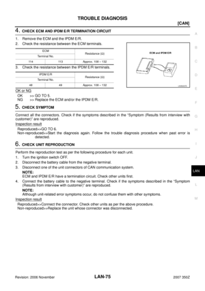
2. CHECK HARNESS FOR OPEN CIRCUIT
1. Disconnect the connector of VDC/TCS/ABS control unit.
2. Check the resistance between the VDC/TCS/ABS control unit harness connector terminals.
OK or NG
OK >> GO TO 3.
NG >> Repair the VDC/TCS/ABS control unit branch line.
3. CHECK POWER SUPPLY AND GROUND CIRCUIT
Check the power supply and the ground circuit of the VDC/TCS/ABS control unit. Refer to BRC-87, "
Wiring
Diagram — VDC —" .
OK or NG
OK >>�Present error: Replace the VDC/TCS/ABS control unit. Refer to BRC-129, "Removal and Instal-
lation" .
�Past error: Error was detected in the VDC/TCS/ABS control unit branch line.
NG >> Repair the power supply and the ground circuit.
TCM Branch Line CircuitNKS0054Q
INSPECTION PROCEDURE
1. CHECK CONNECTOR
1. Turn the ignition switch OFF.
2. Disconnect the battery cable from the negative terminal.
3. Check the following terminals and connectors for damage, bend and loose connection (unit side and con-
nector side).
–A/T assembly connector
–Harness connector F102
–Harness connector M72
OK or NG
OK >> GO TO 2.
NG >> Repair the terminal and connector.
VDC/TCS/ABS control unit harness connector
Resistance (Ω)
Connector No. Terminal No.
B114 61 63 Approx. 54 – 66
Page 70 of 76
![NISSAN 350Z 2007 Z33 LAN System Workshop Manual LAN-70
[CAN]
TROUBLE DIAGNOSIS
Revision: 2006 November2007 350Z
2. CHECK HARNESS FOR OPEN CIRCUIT
1. Disconnect the connector of A/T assembly.
2. Check the resistance between the A/T assembly harness](/manual-img/5/774/w960_774-69.png "NISSAN 350Z 2007 Z33 LAN System Workshop Manual LAN-70
[CAN]
TROUBLE DIAGNOSIS
Revision: 2006 November2007 350Z
2. CHECK HARNESS FOR OPEN CIRCUIT
1. Disconnect the connector of A/T assembly.
2. Check the resistance between the A/T assembly harness")
LAN-70
[CAN]
TROUBLE DIAGNOSIS
Revision: 2006 November2007 350Z
2. CHECK HARNESS FOR OPEN CIRCUIT
1. Disconnect the connector of A/T assembly.
2. Check the resistance between the A/T assembly harness connector terminals.
OK or NG
OK >> GO TO 3.
NG >> Repair the TCM branch line.
3. CHECK POWER SUPPLY AND GROUND CIRCUIT
Check the power supply and the ground circuit of the TCM. Refer to AT- 1 6 2 , "
MAIN POWER SUPPLY AND
GROUND CIRCUIT" .
OK or NG
OK >>�Present error: Replace the control valve with TCM. Refer to AT- 2 4 2 , "Removal and Installation"
.
�Past error: Error was detected in the TCM branch line.
NG >> Repair the power supply and the ground circuit.
BCM Branch Line CircuitNKS0054R
INSPECTION PROCEDURE
1. CHECK CONNECTOR
1. Turn the ignition switch OFF.
2. Disconnect the battery cable from the negative terminal.
3. Check the terminals and connectors of the BCM for damage, bend and loose connection (unit side and
connector side).
OK or NG
OK >> GO TO 2.
NG >> Repair the terminal and connector.
2. CHECK HARNESS FOR OPEN CIRCUIT
1. Disconnect the connector of BCM.
2. Check the resistance between the BCM harness connector terminals.
OK or NG
OK >> GO TO 3.
NG >> Repair the BCM branch line.
3. CHECK POWER SUPPLY AND GROUND CIRCUIT
Check the power supply and the ground circuit of the BCM. Refer to BCS-11, "
Schematic" .
OK or NG
OK >>�Present error: Replace the BCM. Refer to BCS-17, "Removal and Installation of BCM" .
�Past error: Error was detected in the BCM branch line.
NG >> Repair the power supply and the ground circuit.
A/T assembly harness connector
Resistance (Ω)
Connector No. Terminal No.
F6 3 8 Approx. 54 – 66
BCM harness connector
Resistance (Ω)
Connector No. Terminal No.
M90 39 40 Approx. 54 – 66
Page 71 of 76
![NISSAN 350Z 2007 Z33 LAN System Workshop Manual TROUBLE DIAGNOSIS
LAN-71
[CAN]
C
D
E
F
G
H
I
J
L
MA
B
LAN
Revision: 2006 November2007 350Z
Data Link Connector Branch Line CircuitNKS0054S
INSPECTION PROCEDURE
1. CHECK CONNECTOR
1. Turn the ignition](/manual-img/5/774/w960_774-70.png "NISSAN 350Z 2007 Z33 LAN System Workshop Manual TROUBLE DIAGNOSIS
LAN-71
[CAN]
C
D
E
F
G
H
I
J
L
MA
B
LAN
Revision: 2006 November2007 350Z
Data Link Connector Branch Line CircuitNKS0054S
INSPECTION PROCEDURE
1. CHECK CONNECTOR
1. Turn the ignition")
TROUBLE DIAGNOSIS
LAN-71
[CAN]
C
D
E
F
G
H
I
J
L
MA
B
LAN
Revision: 2006 November2007 350Z
Data Link Connector Branch Line CircuitNKS0054S
INSPECTION PROCEDURE
1. CHECK CONNECTOR
1. Turn the ignition switch OFF.
2. Disconnect the battery cable from the negative terminal.
3. Check the terminals and connectors of the data link connector for damage, bend and loose connection
(connector side and harness side).
OK or NG
OK >> GO TO 2.
NG >> Repair the terminal and connector.
2. CHECK HARNESS FOR OPEN CIRCUIT
Check the resistance between the data link connector terminals.
OK or NG
OK >>�Present error: Check the following items again.
–Decision of CAN system type.
–Not received CONSULT-III data [SELF-DIAG RESULTS, CAN DIAG SUPPORT MNTR (“ECU
list” included)].
–Procedure for detecting root cause.
�Past error: Error was detected in the data link connector branch line circuit.
NG >> Repair the data link connector branch line.
Unified Meter and A/C Amp. Branch Line CircuitNKS0054T
INSPECTION PROCEDURE
1. CHECK CONNECTOR
1. Turn the ignition switch OFF.
2. Disconnect the battery cable from the negative terminal.
3. Check the terminals and connectors of the unified meter and A/C amp. for damage, bend and loose con-
nection (unit side and connector side).
OK or NG
OK >> GO TO 2.
NG >> Repair the terminal and connector.
2. CHECK HARNESS FOR OPEN CIRCUIT
1. Disconnect the connector of unified meter and A/C amp.
2. Check the resistance between the unified meter and A/C amp. harness connector terminals.
OK or NG
OK >> GO TO 3.
NG >> Repair the unified meter and A/C amp. branch line.
Data link connector
Resistance (Ω)
Connector No. Terminal No.
M8 6 14 Approx. 54 – 66
Unified meter and A/C amp. harness connector
Resistance (Ω)
Connector No. Terminal No.
M48 1 11 Approx. 54 – 66
Page 72 of 76
![NISSAN 350Z 2007 Z33 LAN System Workshop Manual LAN-72
[CAN]
TROUBLE DIAGNOSIS
Revision: 2006 November2007 350Z
3. CHECK POWER SUPPLY AND GROUND CIRCUIT
Check the power supply and the ground circuit of the unified meter and A/C amp. Refer to DI-49,](/manual-img/5/774/w960_774-71.png "NISSAN 350Z 2007 Z33 LAN System Workshop Manual LAN-72
[CAN]
TROUBLE DIAGNOSIS
Revision: 2006 November2007 350Z
3. CHECK POWER SUPPLY AND GROUND CIRCUIT
Check the power supply and the ground circuit of the unified meter and A/C amp. Refer to DI-49,")
LAN-72
[CAN]
TROUBLE DIAGNOSIS
Revision: 2006 November2007 350Z
3. CHECK POWER SUPPLY AND GROUND CIRCUIT
Check the power supply and the ground circuit of the unified meter and A/C amp. Refer to DI-49, "
Power Sup-
ply and Ground Circuit Inspection" .
OK or NG
OK >>�Present error: Replace the unified meter and A/C amp. Refer to DI-55, "Removal and Installa-
tion of Unified Meter and A/C Amp." .
�Past error: Error was detected in the unified meter and A/C amp. branch line.
NG >> Repair the power supply and the ground circuit.
Steering Angle Sensor Branch Line CircuitNKS0054U
INSPECTION PROCEDURE
1. CHECK CONNECTOR
1. Turn the ignition switch OFF.
2. Disconnect the battery cable from the negative terminal.
3. Check the terminals and connectors of the steering angle sensor for damage, bend and loose connection
(unit side and connector side).
OK or NG
OK >> GO TO 2.
NG >> Repair the terminal and connector.
2. CHECK HARNESS FOR OPEN CIRCUIT
1. Disconnect the connector of steering angle sensor.
2. Check the resistance between the steering angle sensor harness connector terminals.
OK or NG
OK >> GO TO 3.
NG >> Repair the steering angle sensor branch line.
3. CHECK POWER SUPPLY AND GROUND CIRCUIT
Check the power supply and the ground circuit of the steering angle sensor. Refer to BRC-86, "
Schematic" .
OK or NG
OK >>�Present error: Replace the steering angle sensor. Refer to BRC-133, "Removal and Installa-
tion" .
�Past error: Error was detected in the steering angle sensor branch line.
NG >> Repair the power supply and the ground circuit.
ABS Actuator and Electric Unit (Control Unit) Branch Line CircuitNKS0054V
INSPECTION PROCEDURE
1. CHECK CONNECTOR
1. Turn the ignition switch OFF.
2. Disconnect the battery cable from the negative terminal.
3. Check the terminals and connectors of the ABS actuator and electric unit (control unit) for damage, bend
and loose connection (unit side and connector side).
OK or NG
OK >> GO TO 2.
NG >> Repair the terminal and connector.
Steering angle sensor harness connector
Resistance (Ω)
Connector No. Terminal No.
M22 4 5 Approx. 54 – 66