Page 1 of 22

FSU-1
FRONT SUSPENSION
E SUSPENSION
CONTENTS
C
D
F
G
H
I
J
K
L
M
SECTION FSU
A
B
FSU
Revision: 2006 November2007 350Z
FRONT SUSPENSION
PRECAUTIONS .......................................................... 2
Caution ..................................................................... 2
PREPARATION ........................................................... 3
Special Service Tools ............................................... 3
Commercial Service Tools ........................................ 3
NOISE, VIBRATION AND HARSHNESS (NVH)
TROUBLESHOOTING ................................................ 4
NVH Troubleshooting Chart ..................................... 4
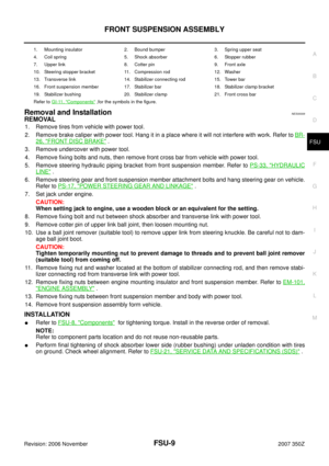
FRONT SUSPENSION ASSEMBLY ........................... 5
On-Vehicle Inspection .............................................. 5
INSPECTION OF BALL JOINT END PLAY OF
EACH LINK ........................................................... 5
SHOCK ABSORBER INSPECTION ..................... 5
Wheel Alignment Inspection ..................................... 6
DESCRIPTION ...................................................... 6
PRELIMINARY CHECK ........................................ 6
GENERAL INFORMATION AND RECOMMEN-
DATIONS .............................................................. 6
THE ALIGNMENT PROCESS .............................. 7
INSPECTION OF CAMBER, CASTER AND
KINGPIN INCLINATION ANGLES ........................ 7
Components ............................................................. 8
Removal and Installation .......................................... 9
REMOVAL ............................................................. 9
INSTALLATION ..................................................... 9
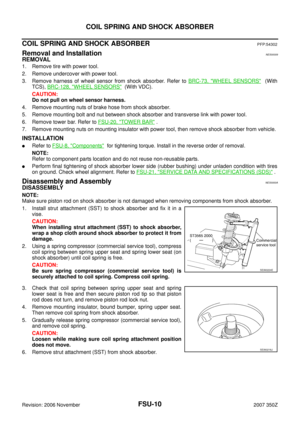
COIL SPRING AND SHOCK ABSORBER ............... 10
Removal and Installation ........................................ 10
REMOVAL ........................................................... 10
INSTALLATION ................................................... 10
Disassembly and Assembly ................................... 10
DISASSEMBLY ................................................... 10
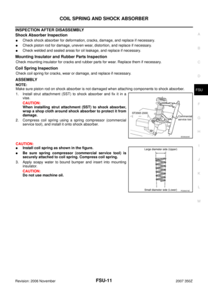
INSPECTION AFTER DISASSEMBLY ................ 11
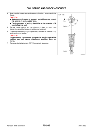
ASSEMBLY .......................................................... 11TRANSVERSE LINK ................................................. 13
Removal and Installation ........................................ 13
REMOVAL ........................................................... 13
INSPECTION AFTER REMOVAL ....................... 13
INSTALLATION ................................................... 13
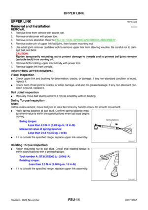
UPPER LINK ............................................................. 14
Removal and Installation ........................................ 14
REMOVAL ........................................................... 14
INSPECTION AFTER REMOVAL ....................... 14
INSTALLATION ................................................... 15
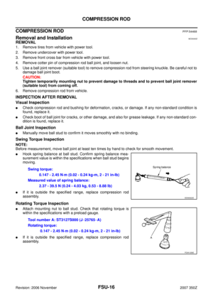
COMPRESSION ROD ............................................... 16
Removal and Installation ........................................ 16
REMOVAL ........................................................... 16
INSPECTION AFTER REMOVAL ....................... 16
AXIAL END PLAY INSPECTION ......................... 17
INSTALLATION ................................................... 17
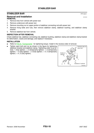
STABILIZER BAR ..................................................... 18
Removal and Installation ........................................ 18
REMOVAL ........................................................... 18
INSPECTION AFTER REMOVAL ....................... 18
INSTALLATION ................................................... 18
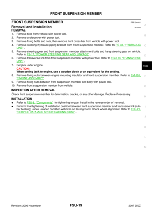
FRONT SUSPENSION MEMBER ............................. 19
Removal and Installation ........................................ 19
REMOVAL ........................................................... 19
INSPECTION AFTER REMOVAL ....................... 19
INSTALLATION ................................................... 19
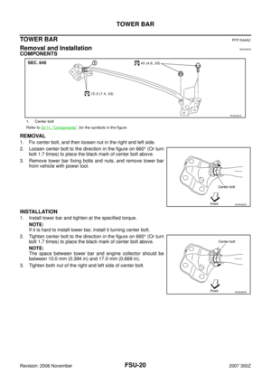
TOWER BAR ............................................................ 20
Removal and Installation ........................................ 20
COMPONENTS ................................................... 20
REMOVAL ........................................................... 20
INSTALLATION ................................................... 20
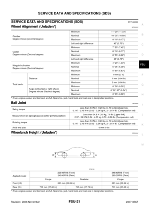
SERVICE DATA AND SPECIFICATIONS (SDS) ...... 21
Wheel Alignment (Unladen*) .................................. 21
Ball Joint ................................................................. 21
Wheelarch Height (Unladen*) ................................. 21
Page 2 of 22
FSU-2
PRECAUTIONS
Revision: 2006 November2007 350Z
PRECAUTIONSPFP:00001
CautionNES00001
�When installing rubber bushings, final tightening must be carried out under unladen conditions with tires
on ground. Oil will shorten the life of rubber bushings. Be sure to wipe off any spilled oil.
�Unladen conditions mean that fuel, engine coolant and lubricant are full. Spare tire, jack, hand tools and
mats are in designated positions.
�After servicing suspension parts, be sure to check wheel alignment.
�Caulking nuts are not reusable. Always use new ones when installing. Since new caulking nuts are pre-
oiled, tighten as they are.
�Avoid burden to front cross bar.
Page 3 of 22
PREPARATION
FSU-3
C
D
F
G
H
I
J
K
L
MA
B
FSU
Revision: 2006 November2007 350Z
PREPARATIONPFP:00002
Special Service ToolsNES00002
The actual shapes of Kent-Moore tools may differ from those of special service tools illustrated here.
Commercial Service ToolsNES00003
Tool number
(Kent-Moore No.)
Tool nameDescription
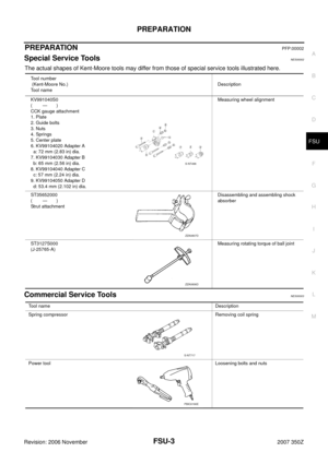
KV991040S0
( — )
CCK gauge attachment
1. Plate
2. Guide bolts
3. Nuts
4. Springs
5. Center plate
6. KV99104020 Adapter A
a: 72 mm (2.83 in) dia.
7. KV99104030 Adapter B
b: 65 mm (2.56 in) dia.
8. KV99104040 Adapter C
c: 57 mm (2.24 in) dia.
9. KV99104050 Adapter D
d: 53.4 mm (2.102 in) dia.Measuring wheel alignment
ST35652000
( — )
Strut attachmentDisassembling and assembling shock
absorber
ST3127S000
(J-25765-A)Measuring rotating torque of ball joint
S-NT498
ZZA0807D
ZZA0806D
Tool nameDescription
Spring compressor Removing coil spring
Power toolLoosening bolts and nuts
S-NT717
PBIC0190E
Page 4 of 22
 TROUBLESHOOTING
Revision: 2006 November2007 350Z
NOISE, VIBRATION AND HARSHNESS (NVH) TROUBLESHOOTINGPFP:00003
NVH Troubleshooting ChartNES00004
Use chart be")
FSU-4
NOISE, VIBRATION AND HARSHNESS (NVH) TROUBLESHOOTING
Revision: 2006 November2007 350Z
NOISE, VIBRATION AND HARSHNESS (NVH) TROUBLESHOOTINGPFP:00003
NVH Troubleshooting ChartNES00004
Use chart below to help you find the cause of the symptom. If necessary, repair or replace these parts.
×: ApplicableReference page
FSU-8FSU-11—
—
—
FSU-8FSU-6FSU-18
NVH in PR section
NVH in RFD section.
NVH in FAX and FSU section.
NVH in WT section.
NVH in WT section.
NVH in RAX section.
NVH in BR section.
NVH in PS section.
Possible cause and SUSPECTED PARTS
Improper installation, looseness
Shock absorber deformation, damage or deflection
Bushing or mounting deterioration
Parts interference
Spring fatigue
Suspension looseness
Incorrect wheel alignment
Stabilizer bar fatigue
PROPELLER SHAFT
DIFFERENTIAL
FRONT AXLE AND FRONT SUSPENSION
TIRES
ROAD WHEEL
DRIVE SHAFT
BRAKES
STEERING
Symptom FRONT SUSPENSIONNoise××××× × ××× ×××××
Shake×××× × × × ×××××
Vibration××××× × ×× × ×
Shimmy×××× × ××× ××
Judder××× ××× ××
Poor quality ride or han-
dling×× × × × ×× × × ×
Page 5 of 22

FRONT SUSPENSION ASSEMBLY
FSU-5
C
D
F
G
H
I
J
K
L
MA
B
FSU
Revision: 2006 November2007 350Z
FRONT SUSPENSION ASSEMBLYPFP:54010
On-Vehicle InspectionNES00005
Make sure the mounting conditions (looseness, back lash) of each component and component statues (wear,
damage) are normal.
INSPECTION OF BALL JOINT END PLAY OF EACH LINK
1. Set front wheels in a straight-ahead position. Do not depress brake pedal.
2. Check ball joint axial end play of each link.
CAUTION:
Be careful not to damage ball joint boot.
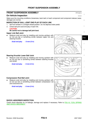
Upper Link Ball Joint
�Measure axial end play by installing and moving up/down with
an iron pry bar or something similar between upper link and
steering knuckle.
Steering Knuckle Lower Ball Joint
�Measure axial end play by installing and moving up/down with
an iron pry bar or something similar between steering knuckle
and wheel.
Compression Rod Ball Joint
�Measure axial end play by installing and moving up/down with
an iron pry bar or something similar between compression rod
and transverse link.
SHOCK ABSORBER INSPECTION
Check shock absorber for oil leakage, damage and replace if necessary. Refer to FSU-10, "COIL SPRING
AND SHOCK ABSORBER" . Axial end play : 0 mm (0 in)
SEIA0242J
Axial end play : 0 mm (0 in)
SEIA0243J
Axial end play : 0 mm (0 in)
SEIA0244J
Page 6 of 22

FSU-6
FRONT SUSPENSION ASSEMBLY
Revision: 2006 November2007 350Z
Wheel Alignment InspectionNES00006
DESCRIPTION
�Measure wheel alignment under unladen conditions.
NOTE:
Unladen conditions mean that fuel, engine coolant, and lubricant are full. Spare tire, jack, hand tools and
mats are designated positions.
PRELIMINARY CHECK
�Check tires for improper air pressure and wear.
�Check road wheels for runout.
�Check wheel bearing axial end play.
�Check ball joint axial end play of compression rod, upper link, and steering knuckle
�Check shock absorber operation.
�Check each mounting part of axle and suspension for looseness and deformation.
�Check each link, rod and member for cracks, deformation and other damage.
�Check vehicle posture.
GENERAL INFORMATION AND RECOMMENDATIONS
�A four-wheel thrust alignment should be performed.
–This type of alignment is recommended for any NISSAN/INFINITI vehicle.
–The four-wheel “thrust” process helps ensure that the vehicle is properly aligned and the steering wheel is
centered.
–The alignment rack itself should be capable of accepting any NISSAN/INFINITI vehicle.
–The rack should be checked to ensure that it is level.
�Make sure the machine is properly calibrated.
–Your alignment equipment should be regularly calibrated in order to give correct information.
–Check with the manufacturer of your specific equipment for their recommended Service/Calibration
Schedule.
Page 7 of 22

FRONT SUSPENSION ASSEMBLY
FSU-7
C
D
F
G
H
I
J
K
L
MA
B
FSU
Revision: 2006 November2007 350Z
THE ALIGNMENT PROCESS
IMPORTANT:
Use only the alignment specifications listed in this Service Manual.
�When displaying the alignment settings, many alignment machines use “indicators”: (Green/red, plus or
minus, Go/No Go). Do not use these indicators.
–The alignment specifications programmed into your machine that operate these indicators may not be cor-
rect.
–This may result in an ERROR.
�Some newer alignment machines are equipped with an optional “Rolling Compensation” method to “com-
pensate” the sensors (alignment targets or head units). Do not use this “Rolling Compensation”
method.
–Use the “Jacking Compensation Method”. After installing the alignment targets or head units, raise the
vehicle and rotate the wheels 1/2 turn both ways.
–See Instructions in the alignment machine you're using for more information on this.
INSPECTION OF CAMBER, CASTER AND KINGPIN INCLINATION ANGLES
�Camber, caster, kingpin inclination angles cannot be adjusted.
�Before inspection, mount front wheels onto turning radius gauge. Mount rear wheels onto a stand that has
same height so vehicle will remain horizontal.
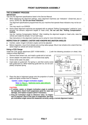
Using a CCK Gauge
Install the CCK gauge attachment [SST: KV991040S0 ( – )] with the following procedure on wheel, then
measure wheel alignment.
1. Remove there wheel nuts, and install a guide bolt to hub bolt.
2. Screw adapter into plate body until it contacts body tightly.
3. Screw center plate into plate.
4. Insert plate on guide bolt. Put spring in, and then evenly screw
both guide bolt nut. When fastening guide bolt nut, do not com-
pletely compress spring.
5. Place the dent of alignment gauge onto the projection of center
plate and tightly contact them to measure.
CAUTION:
�If camber, caster, or kingpin inclination angle is outside
the standard, check front suspension parts for wear and
damage, and replace suspect parts if necessary.
�King pin inclination angle is reference value, no inspec-
tion is required. (Due to the type of suspension, the king-
pin inclination angle cannot be measured correctly using a normal alignment tester.)
SEIA0240E
Camber, caster, kingpin inclination angles:
Refer to FSU-21, "
SERVICE DATA AND SPECIFI-
CATIONS (SDS)" .
SEIA0241E
Page 8 of 22
FSU-8
FRONT SUSPENSION ASSEMBLY
Revision: 2006 November2007 350Z
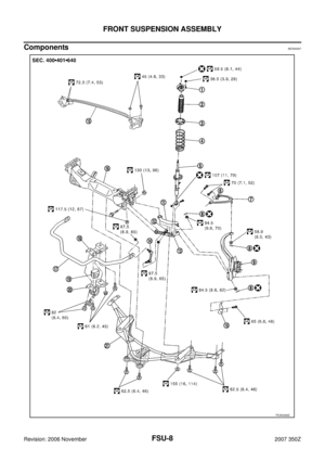
ComponentsNES00007
PEIA0066E