Page 2 of 22
FSU-2
PRECAUTIONS
Revision: 2006 November2007 350Z
PRECAUTIONSPFP:00001
CautionNES00001
�When installing rubber bushings, final tightening must be carried out under unladen conditions with tires
on ground. Oil will shorten the life of rubber bushings. Be sure to wipe off any spilled oil.
�Unladen conditions mean that fuel, engine coolant and lubricant are full. Spare tire, jack, hand tools and
mats are in designated positions.
�After servicing suspension parts, be sure to check wheel alignment.
�Caulking nuts are not reusable. Always use new ones when installing. Since new caulking nuts are pre-
oiled, tighten as they are.
�Avoid burden to front cross bar.
Page 6 of 22

FSU-6
FRONT SUSPENSION ASSEMBLY
Revision: 2006 November2007 350Z
Wheel Alignment InspectionNES00006
DESCRIPTION
�Measure wheel alignment under unladen conditions.
NOTE:
Unladen conditions mean that fuel, engine coolant, and lubricant are full. Spare tire, jack, hand tools and
mats are designated positions.
PRELIMINARY CHECK
�Check tires for improper air pressure and wear.
�Check road wheels for runout.
�Check wheel bearing axial end play.
�Check ball joint axial end play of compression rod, upper link, and steering knuckle
�Check shock absorber operation.
�Check each mounting part of axle and suspension for looseness and deformation.
�Check each link, rod and member for cracks, deformation and other damage.
�Check vehicle posture.
GENERAL INFORMATION AND RECOMMENDATIONS
�A four-wheel thrust alignment should be performed.
–This type of alignment is recommended for any NISSAN/INFINITI vehicle.
–The four-wheel “thrust” process helps ensure that the vehicle is properly aligned and the steering wheel is
centered.
–The alignment rack itself should be capable of accepting any NISSAN/INFINITI vehicle.
–The rack should be checked to ensure that it is level.
�Make sure the machine is properly calibrated.
–Your alignment equipment should be regularly calibrated in order to give correct information.
–Check with the manufacturer of your specific equipment for their recommended Service/Calibration
Schedule.
Page 9 of 22

FRONT SUSPENSION ASSEMBLY
FSU-9
C
D
F
G
H
I
J
K
L
MA
B
FSU
Revision: 2006 November2007 350Z
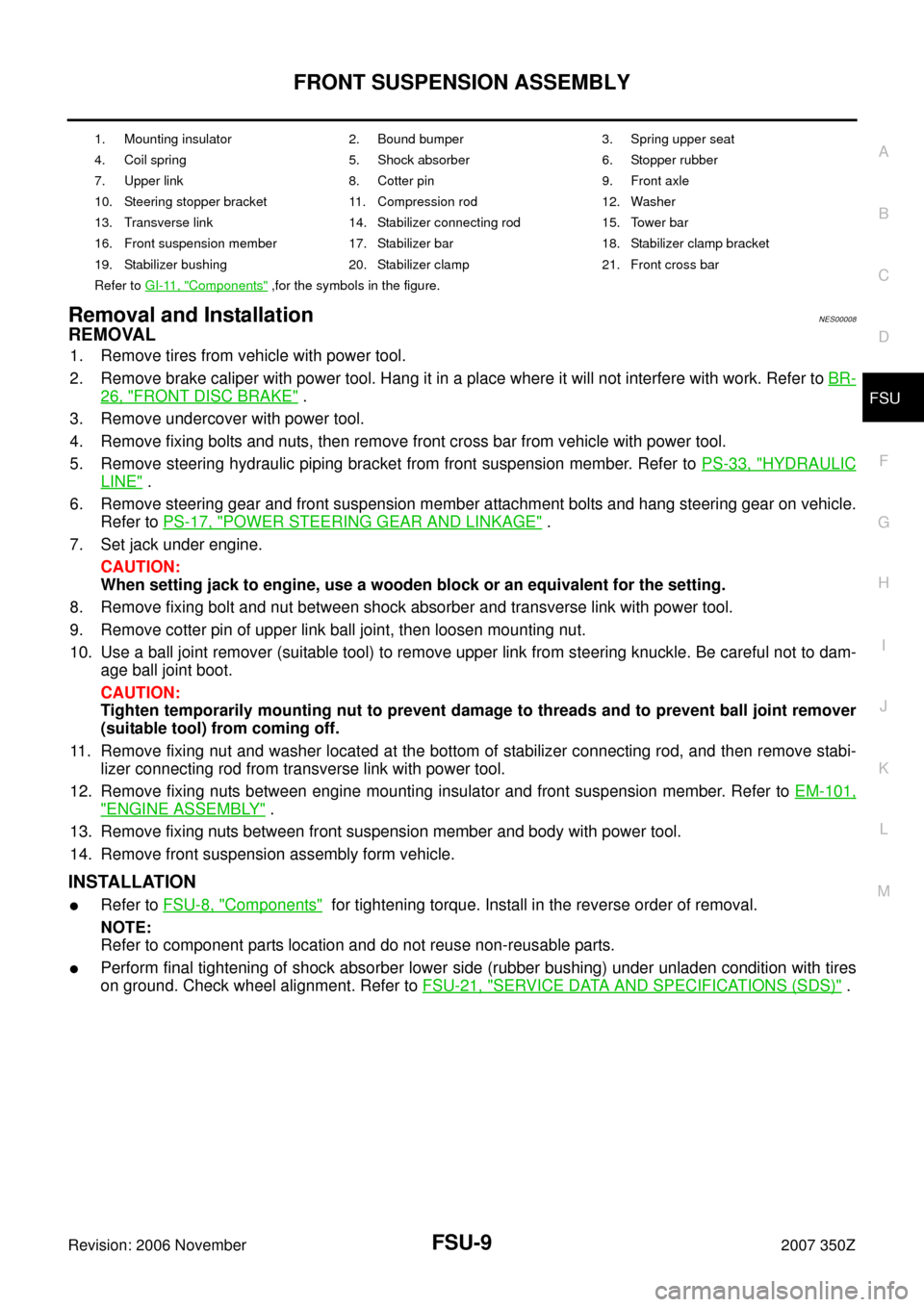
Removal and InstallationNES00008
REMOVAL
1. Remove tires from vehicle with power tool.
2. Remove brake caliper with power tool. Hang it in a place where it will not interfere with work. Refer to BR-
26, "FRONT DISC BRAKE" .
3. Remove undercover with power tool.
4. Remove fixing bolts and nuts, then remove front cross bar from vehicle with power tool.
5. Remove steering hydraulic piping bracket from front suspension member. Refer to PS-33, "
HYDRAULIC
LINE" .
6. Remove steering gear and front suspension member attachment bolts and hang steering gear on vehicle.
Refer to PS-17, "
POWER STEERING GEAR AND LINKAGE" .
7. Set jack under engine.
CAUTION:
When setting jack to engine, use a wooden block or an equivalent for the setting.
8. Remove fixing bolt and nut between shock absorber and transverse link with power tool.
9. Remove cotter pin of upper link ball joint, then loosen mounting nut.
10. Use a ball joint remover (suitable tool) to remove upper link from steering knuckle. Be careful not to dam-
age ball joint boot.
CAUTION:
Tighten temporarily mounting nut to prevent damage to threads and to prevent ball joint remover
(suitable tool) from coming off.
11. Remove fixing nut and washer located at the bottom of stabilizer connecting rod, and then remove stabi-
lizer connecting rod from transverse link with power tool.
12. Remove fixing nuts between engine mounting insulator and front suspension member. Refer to EM-101,
"ENGINE ASSEMBLY" .
13. Remove fixing nuts between front suspension member and body with power tool.
14. Remove front suspension assembly form vehicle.
INSTALLATION
�Refer to FSU-8, "Components" for tightening torque. Install in the reverse order of removal.
NOTE:
Refer to component parts location and do not reuse non-reusable parts.
�Perform final tightening of shock absorber lower side (rubber bushing) under unladen condition with tires
on ground. Check wheel alignment. Refer to FSU-21, "
SERVICE DATA AND SPECIFICATIONS (SDS)" .
1. Mounting insulator 2. Bound bumper 3. Spring upper seat
4. Coil spring 5. Shock absorber 6. Stopper rubber
7. Upper link 8. Cotter pin 9. Front axle
10. Steering stopper bracket 11. Compression rod 12. Washer
13. Transverse link 14. Stabilizer connecting rod 15. Tower bar
16. Front suspension member 17. Stabilizer bar 18. Stabilizer clamp bracket
19. Stabilizer bushing 20. Stabilizer clamp 21. Front cross bar
Refer to GI-11, "
Components" ,for the symbols in the figure.
Page 19 of 22

FRONT SUSPENSION MEMBER
FSU-19
C
D
F
G
H
I
J
K
L
MA
B
FSU
Revision: 2006 November2007 350Z
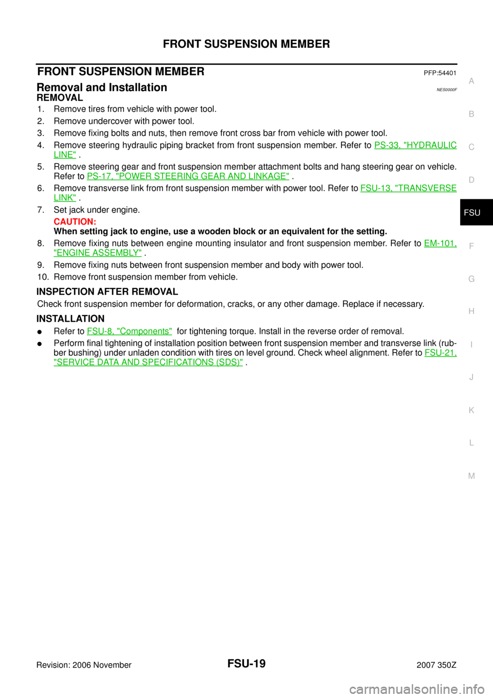
FRONT SUSPENSION MEMBERPFP:54401
Removal and InstallationNES0000F
REMOVAL
1. Remove tires from vehicle with power tool.
2. Remove undercover with power tool.
3. Remove fixing bolts and nuts, then remove front cross bar from vehicle with power tool.
4. Remove steering hydraulic piping bracket from front suspension member. Refer to PS-33, "
HYDRAULIC
LINE" .
5. Remove steering gear and front suspension member attachment bolts and hang steering gear on vehicle.
Refer to PS-17, "
POWER STEERING GEAR AND LINKAGE" .
6. Remove transverse link from front suspension member with power tool. Refer to FSU-13, "
TRANSVERSE
LINK" .
7. Set jack under engine.
CAUTION:
When setting jack to engine, use a wooden block or an equivalent for the setting.
8. Remove fixing nuts between engine mounting insulator and front suspension member. Refer to EM-101,
"ENGINE ASSEMBLY" .
9. Remove fixing nuts between front suspension member and body with power tool.
10. Remove front suspension member from vehicle.
INSPECTION AFTER REMOVAL
Check front suspension member for deformation, cracks, or any other damage. Replace if necessary.
INSTALLATION
�Refer to FSU-8, "Components" for tightening torque. Install in the reverse order of removal.
�Perform final tightening of installation position between front suspension member and transverse link (rub-
ber bushing) under unladen condition with tires on level ground. Check wheel alignment. Refer to FSU-21,
"SERVICE DATA AND SPECIFICATIONS (SDS)" .