Page 17 of 22
COMPRESSION ROD
FSU-17
C
D
F
G
H
I
J
K
L
MA
B
FSU
Revision: 2006 November2007 350Z
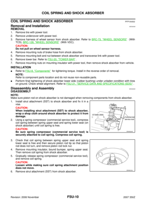
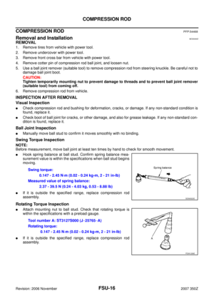
AXIAL END PLAY INSPECTION
�Move tip of ball joint in axial direction to check for looseness.
�If it is outside the specified range, replace compression rod assembly.
INSTALLATION
�Refer to FSU-8, "Components" for tightening torque. Install in the reverse order of removal.
NOTE:
Refer to component parts location and do not reuse non-reusable parts.
�Perform final tightening of installation position between front suspension member and front cross bar (rub-
ber bushing) under unladen condition with tires on ground. Check wheel alignment. Refer to FSU-21,
"SERVICE DATA AND SPECIFICATIONS (SDS)" . Axial end play : 0 mm (0 in)
Page 18 of 22

FSU-18
STABILIZER BAR
Revision: 2006 November2007 350Z
STABILIZER BARPFP:54611
Removal and InstallationNES0000E
REMOVAL
1. Remove tires from vehicle with power tool.
2. Remove undercover with power tool.
3. Remove mounting nut on upper portion of stabilizer connecting rod with power tool.
4. Remove fixing bolts and nuts, then remove stabilizer clamp, stabilizer bushing, and stabilizer clamp
bracket.
5. Remove stabilizer bar from vehicle.
INSPECTION AFTER REMOVAL
Check stabilizer bar, stabilizer connecting rod, stabilizer bushing, stabilizer clamp and stabilizer clamp bracket
for deformation, cracks and damage, and replace if necessary.
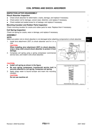
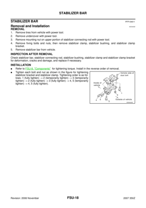
INSTALLATION
�Refer to FSU-8, "Components" for tightening torque. Install in the reverse order of removal.
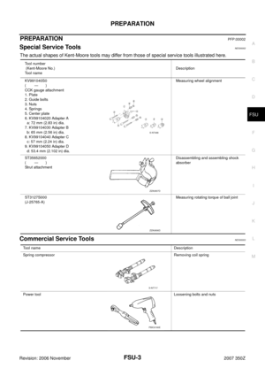
�Tighten each bolt and nut as shown in the figure for tightening
stabilizer bracket and stabilizer clamp. Tightening order is as fol-
lows. 1 (fully tighten) → 2 (temporarily tighten) → 3 (temporarily
tighten) → 2 (fully tighten) → 3 (fully tighten) → 4, 5 (temporarily
tighten) → 4, 5 (fully tighten).
SEIA0420E
Page 19 of 22

FRONT SUSPENSION MEMBER
FSU-19
C
D
F
G
H
I
J
K
L
MA
B
FSU
Revision: 2006 November2007 350Z
FRONT SUSPENSION MEMBERPFP:54401
Removal and InstallationNES0000F
REMOVAL
1. Remove tires from vehicle with power tool.
2. Remove undercover with power tool.
3. Remove fixing bolts and nuts, then remove front cross bar from vehicle with power tool.
4. Remove steering hydraulic piping bracket from front suspension member. Refer to PS-33, "
HYDRAULIC
LINE" .
5. Remove steering gear and front suspension member attachment bolts and hang steering gear on vehicle.
Refer to PS-17, "
POWER STEERING GEAR AND LINKAGE" .
6. Remove transverse link from front suspension member with power tool. Refer to FSU-13, "
TRANSVERSE
LINK" .
7. Set jack under engine.
CAUTION:
When setting jack to engine, use a wooden block or an equivalent for the setting.
8. Remove fixing nuts between engine mounting insulator and front suspension member. Refer to EM-101,
"ENGINE ASSEMBLY" .
9. Remove fixing nuts between front suspension member and body with power tool.
10. Remove front suspension member from vehicle.
INSPECTION AFTER REMOVAL
Check front suspension member for deformation, cracks, or any other damage. Replace if necessary.
INSTALLATION
�Refer to FSU-8, "Components" for tightening torque. Install in the reverse order of removal.
�Perform final tightening of installation position between front suspension member and transverse link (rub-
ber bushing) under unladen condition with tires on level ground. Check wheel alignment. Refer to FSU-21,
"SERVICE DATA AND SPECIFICATIONS (SDS)" .
Page 20 of 22
FSU-20
TOWER BAR
Revision: 2006 November2007 350Z
TOWER BARPFP:544A2
Removal and Installation NES0000G
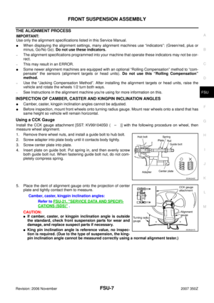
COMPONENTS
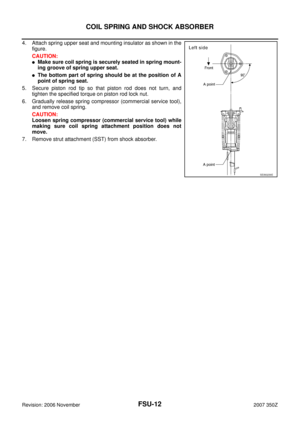
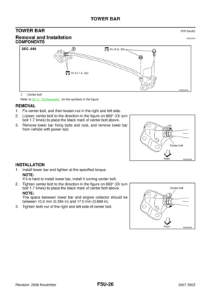
REMOVAL
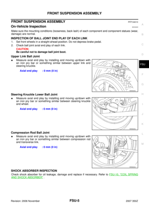
1. Fix center bolt, and then loosen nut in the right and left side.
2. Loosen center bolt to the direction in the figure on 660° (Or turn
bolt 1.7 times) to place the black mark of center bolt above.
3. Remove tower bar fixing bolts and nuts, and remove tower bar
from vehicle with power tool.
INSTALLATION
1. Install tower bar and tighten at the specified torque.
NOTE:
If it is hard to install tower bar, install it turning center bolt.
2. Tighten center bolt to the direction in the figure on 660° (Or turn
bolt 1.7 times) to place the black mark of center bolt above.
NOTE:
The space between tower bar and engine collector should be
between 10.0 mm (0.394 in) and 17.0 mm (0.669 in).
3. Tighten both nut of the right and left side of center bolt.
1. Center bolt
Refer to GI-11, "
Components" ,for the symbols in the figure
PEIA0067E
SEIA0262E
SEIA0263E
Page 21 of 22

FSU-21
C
D
F
G
H
I
J
K
L
MA
B
FSU
Revision: 2006 November2007 350Z
SERVICE DATA AND SPECIFICATIONS (SDS)PFP:00030
Wheel Alignment (Unladen*)NES0000H
*: Fuel, engi")
SERVICE DATA AND SPECIFICATIONS (SDS)
FSU-21
C
D
F
G
H
I
J
K
L
MA
B
FSU
Revision: 2006 November2007 350Z
SERVICE DATA AND SPECIFICATIONS (SDS)PFP:00030
Wheel Alignment (Unladen*)NES0000H
*: Fuel, engine coolant and lubricant are full. Spare tire, jack, hand tools and mats are in designated positions.
Ball JointNES0000I
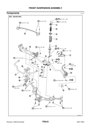
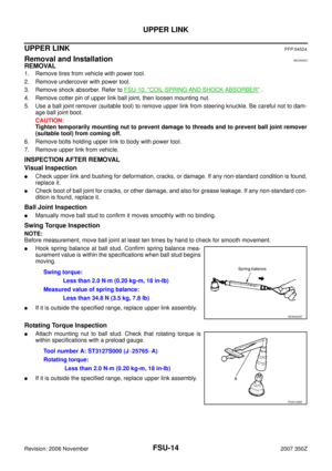
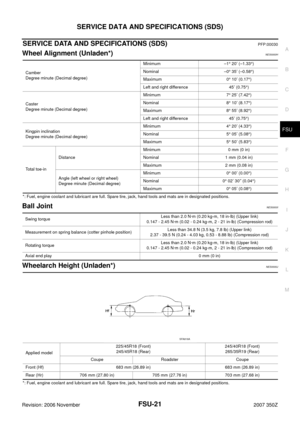
Wheelarch Height (Unladen*)NES0000J
*: Fuel, engine coolant and lubricant are full. Spare tire, jack, hand tools and mats are in designated positions.Camber
Degree minute (Decimal degree)Minimum –1° 20′ (–1.33°)
Nominal –0° 35′ (–0.58°)
Maximum 0° 10′ (0.17°)
Left and right difference 45′ (0.75°)
Caster
Degree minute (Decimal degree)Minimum 7° 25′ (7.42°)
Nominal 8° 10′ (8.17°)
Maximum 8° 55′ (8.92°)
Left and right difference 45′ (0.75°)
Kingpin inclination
Degree minute (Decimal degree)Minimum 4° 20′ (4.33°)
Nominal 5° 05′ (5.08°)
Maximum 5° 50′ (5.83°)
Total toe-inDistanceMinimum 0 mm (0 in)
Nominal 1 mm (0.04 in)
Maximum 2 mm (0.08 in)
Angle (left wheel or right wheel)
Degree minute (Decimal degree)Minimum 0° 00′ (0.00°)
Nominal 0° 02′ 30″ (0.04°)
Maximum 0° 05′ (0.08°)
Swing torqueLess than 2.0 N·m (0.20 kg-m, 18 in-lb) (Upper link)
0.147 - 2.45 N·m (0.02 - 0.24 kg-m, 2 - 21 in-lb) (Compression rod)
Measurement on spring balance (cotter pinhole position)Less than 34.8 N (3.5 kg, 7.8 lb) (Upper link)
2.37 - 39.5 N (0.24 - 4.03 kg, 0.53 - 8.88 lb) (Compression rod)
Rotating torqueLess than 2.0 N·m (0.20 kg-m, 18 in-lb) (Upper link)
0.147 - 2.45 N·m (0.02 - 0.24 kg-m, 2 - 21 in-lb) (Compression rod)
Axial end play0 mm (0 in)
Applied model225/45R18 (Front)
245/45R18 (Rear)245/40R18 (Front)
265/35R19 (Rear)
Coupe Roadster Coupe
Front (Hf) 683 mm (26.89 in) 683 mm (26.89 in)
Rear (Hr) 706 mm (27.80 in) 705 mm (27.76 in) 703 mm (27.68 in)
SFA818A
Page 22 of 22
FSU-22
SERVICE DATA AND SPECIFICATIONS (SDS)
Revision: 2006 November2007 350Z
Page:
< prev 1-8 9-16 17-24


Revision: 2006 November2007 350Z")