Page 17 of 50
REAR BUMPER
EI-17
C
D
E
F
G
H
J
K
L
MA
B
EI
Revision: 2006 November2007 350Z
REAR BUMPERPFP:H5022
Removal and InstallationNIS0008G
CAUTION:
Bumper fascia is made of resin. Do not apply strong force to it, and be careful to prevent contact with-
oil.
PIIB7223E
Page 18 of 50

EI-18
REAR BUMPER
Revision: 2006 November2007 350Z
REMOVAL
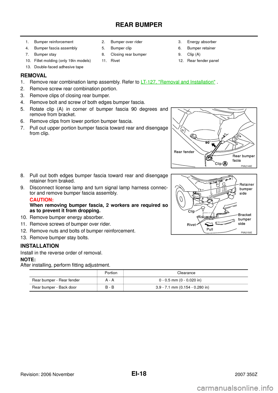
1. Remove rear combination lamp assembly. Refer to LT- 1 2 7 , "Removal and Installation" .
2. Remove screw rear combination portion.
3. Remove clips of closing rear bumper.
4. Remove bolt and screw of both edges bumper fascia.
5. Rotate clip (A) in corner of bumper fascia 90 degrees and
remove from bracket.
6. Remove clips from lower portion bumper fascia.
7. Pull out upper portion bumper fascia toward rear and disengage
from clip.
8. Pull out both edges bumper fascia toward rear and disengage
retainer from braked.
9. Disconnect license lamp and turn signal lamp harness connec-
tor and remove bumper fascia assembly.
CAUTION:
When removing bumper fascia, 2 workers are required so
as to prevent it from dropping.
10. Remove bumper energy absorber.
11. Remove screws of bumper over rider.
12. Remove nuts and bolts of bumper reinforcement.
13. Remove bumper stay bolts.
INSTALLATION
Install in the reverse order of removal.
NOTE:
After installing, perform fitting adjustment.
1. Bumper reinforcement 2. Bumper over rider 3. Energy absorber
4. Bumper fascia assembly 5. Bumper clip 6. Bumper retainer
7. Bumper stay 8. Closing rear bumper 9. Clip (A)
10. Fillet molding (only 19in models) 11. Rivet 12. Rear fender panel
13. Double-faced adhesive tape
PIIA2146E
PIIA2150E
Portion Clearance
Rear bumper - Rear fender A - A 0 - 0.5 mm (0 - 0.020 in)
Rear bumper - Back door B - B 3.9 - 7.1 mm (0.154 - 0.280 in)
Page 19 of 50
REAR BUMPER
EI-19
C
D
E
F
G
H
J
K
L
MA
B
EI
Revision: 2006 November2007 350Z
REMOVAL AND INSTALLATION OF BUMPER SIDE BRACKETS AND FILLET MOLDING
REMOVAL
Shave head of rivet with drill [4.0 to 4.5 mm (0.157 to 0.177 in) dia.]
INSTALLATION
Install parts to fascia firmly with hand riveter.
NOTE:
Use the following rivet, when installing of parts.
Rivet thickness : 1.2 – 6.4 mm (0.047 – 0.252 in)
Under hole diameter : 4.1 – 4.4 mm (0.161 – 0.173 in)
dia.
PIIA0216E
Page 20 of 50
EI-20
COWL TOP
Revision: 2006 November2007 350Z
COWL TOPPFP:66100
Removal and InstallationNIS0008H
REMOVAL
1. Remove clips of hoodledge cover (LH/RH).
2. Remove both wiper arms (LH/RH). Refer to WW-30, "
Removal and Installation of Front Wiper Arms,
Adjustment of Wiper Arms Stop Location" .
3. Remove cowl top seal rubber.
4. Remove clips of cowl top cover (RH) and remove cowl top cover (RH).
5. Remove clips, cap, screws and remove cowl top cover (LH).
6. Remove washer hose from cowl top cover.
INSTALLATION
Install in the reverse order of removal.
CAUTION:
After installing, perform adjustment of wiper arm. Refer to WW-30, "
Removal and Installation of Front
Wiper Arms, Adjustment of Wiper Arms Stop Location" .
PIIA2148E
1. Cowl top cover (RH) 2. Cap 3. Cowl top seal rubber
4. Cap 5. Cowl top cover (LH) 6. Hoodledge cover (LH)
7. Battery 8. Hoodledge cover (RH)
Page 21 of 50
FENDER PROTECTOR
EI-21
C
D
E
F
G
H
J
K
L
MA
B
EI
Revision: 2006 November2007 350Z
FENDER PROTECTORPFP:63840
Removal and InstallationNIS0008I
REMOVAL
1. Remove screws and clips of fender protector.
2. Remove fender protector front and remove fender protector rear.
INSTALLATION
Install in the reverse order of removal.
1. Fender protector (front) 2. Fender protector (rear)
PIIA2140E
Page 22 of 50
EI-22
DOOR OUTSIDE MOLDING
Revision: 2006 November2007 350Z
DOOR OUTSIDE MOLDING PFP:82820
Removal and InstallationNIS0008J
REMOVAL
1. Open windows fully.
2. Remove door finisher. Refer to EI-33, "
Removal and Installation" .
3. Remove rear end of door outside molding screw.
4. Disconnect pawls on front edge of molding.
5. Disconnect pawls in the order from front side of door panel portion, with clip clamp remover.
6. Remove slide molding rearward side, after disconnecting all pawls.
INSTALLATION
Install in the reverse order of removal.
CAUTION:
�Be careful not to apply excessive force when removing because it is easy to deform parts.
�After removal, visually inspect molding, and if it is deformed, replace it with new molding.
1. Door outside molding 2. Front door panel 3. Glass
PIIA2147E
Page 23 of 50
SIDE SILL FINISHER
EI-23
C
D
E
F
G
H
J
K
L
MA
B
EI
Revision: 2006 November2007 350Z
SIDE SILL FINISHERPFP:76852
Removal and InstallationNIS0008K
REMOVAL
1. Remove body side welt. Refer to EI-35, "BODY SIDE TRIM" .
2. Remove kicking plate outer. Refer to EI-35, "
BODY SIDE TRIM" .
3. Remove bolts of side sill finisher lower portion.
4. Remove clips of side sill finisher front and rear portion.
5. Remove bolt and nut of reflector mudguard rear.
6. Insert clip clamp remover between panel and side sill finisher, and pull up side sill finisher.
INSTALLATION
Install in the reverse order of removal.
CAUTION:
When installing side sill finisher, check that clips are securely fitted in panel holes on body, and then
press them in.
1. Side sill finisher 2. Kicking plate outer 3. Reflector mudguard rear
PIIA2139E
Page 24 of 50
EI-24
SIDE SILL FINISHER
Revision: 2006 November2007 350Z
FRONT DEFLECTOR
Removal
Remove screws and clips of front deflector and remove front deflec-
tor.
Installation
Install in the reverse order of removal.
FLOOR FAIRING
Removal
Remove bolts and clip of floor fairing and remove floor fairing.
Installation
Install in the reverse order of removal.
FLOOR SIDE FAIRING
Removal
Remove nuts and bolt of floor side fairing and remove floor side fair-
ing.
Installation
Install in the reverse order of removal.
REAR DEFLECTOR
Removal
Remove nuts and bolt of rear deflector and remove rear deflector.
Installation
Install in the reverse order of removal.
PIIA6835E
PIIA6836E
PIIA6905E