CYLINDER BLOCK
EM-109
C
D
E
F
G
H
I
J
K
L
MA
EM
Revision: 2006 November2007 350Z
7. Drain engine coolant by removing water drain plugs (1, 4) from
cylinder block both sides as shown in the figure.
8. Remove oil pan (upper, lower). Refer to EM-26, "
OIL PAN AND OIL STRAINER" .
9. Remove front timing chain case, timing chain and rear timing chain case. Refer to EM-53, "
TIMING
CHAIN" .
10. Remove cylinder head. Refer to EM-89, "
CYLINDER HEAD" .
11. Remove knock sensor.
CAUTION:
Carefully handle sensor avoiding shocks.
12. Remove rear oil seal.
13. Remove baffle plate from lower cylinder block.
14. Remove piston and connecting rod assembly as follows:
�Before removing piston and connecting rod assembly, check the connecting rod side clearance. Refer
to EM-125, "
CONNECTING ROD SIDE CLEARANCE" .
a. Position crankshaft pin corresponding to connecting rod to be removed onto the bottom dead center.
b. Remove connecting rod bearing cap.
c. Using hammer handle or similar tool, push piston and connect-
ing rod assembly out to the cylinder head side.
CAUTION:
Be careful not to damage the cylinder wall and crankshaft
pin, resulting from an interference of the connecting rod big
end.
15. Remove connecting rod bearings from connecting rod and connecting rod bearing cap.
CAUTION:
Identify installation position, and store them without mixing them up.
16. Remove piston rings form piston.
�Before removing piston rings, check the piston ring side clearance. Refer to EM-126, "PISTON RING
SIDE CLEARANCE" .
2 : Washer
3: Plug
: Engine front
PBIC5014E
PBIC2940E
CYLINDER BLOCK
EM-117
C
D
E
F
G
H
I
J
K
L
MA
EM
Revision: 2006 November2007 350Z
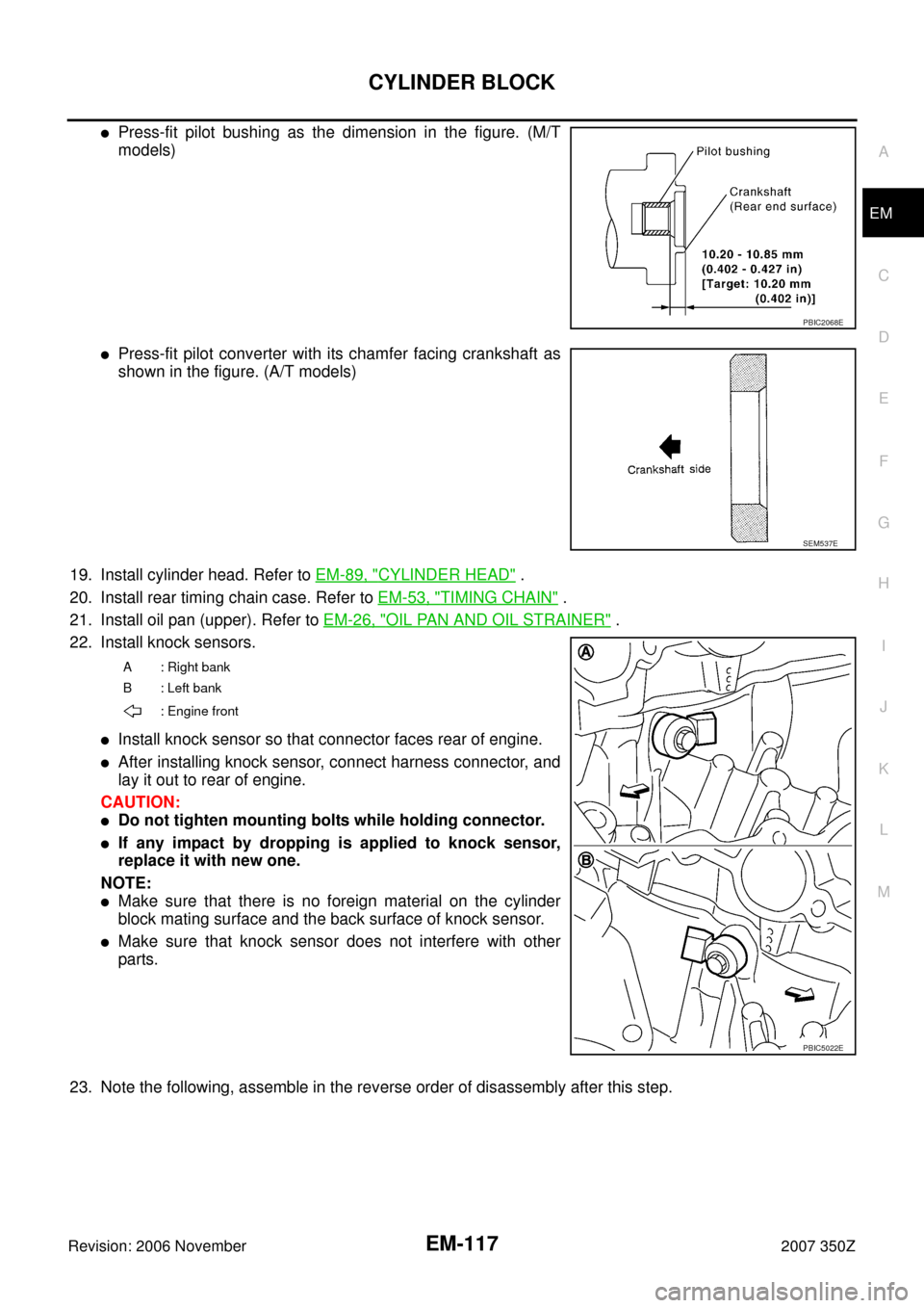
�Press-fit pilot bushing as the dimension in the figure. (M/T
models)
�Press-fit pilot converter with its chamfer facing crankshaft as
shown in the figure. (A/T models)
19. Install cylinder head. Refer to EM-89, "
CYLINDER HEAD" .
20. Install rear timing chain case. Refer to EM-53, "
TIMING CHAIN" .
21. Install oil pan (upper). Refer to EM-26, "
OIL PAN AND OIL STRAINER" .
22. Install knock sensors.
�Install knock sensor so that connector faces rear of engine.
�After installing knock sensor, connect harness connector, and
lay it out to rear of engine.
CAUTION:
�Do not tighten mounting bolts while holding connector.
�If any impact by dropping is applied to knock sensor,
replace it with new one.
NOTE:
�Make sure that there is no foreign material on the cylinder
block mating surface and the back surface of knock sensor.
�Make sure that knock sensor does not interfere with other
parts.
23. Note the following, assemble in the reverse order of disassembly after this step.
PBIC2068E
SEM537E
A : Right bank
B : Left bank
: Engine front
PBIC5022E
 from
cylinder block both sides as shown in the figure.
8.")