Page 26 of 148
EM-26
OIL PAN AND OIL STRAINER
Revision: 2006 November2007 350Z
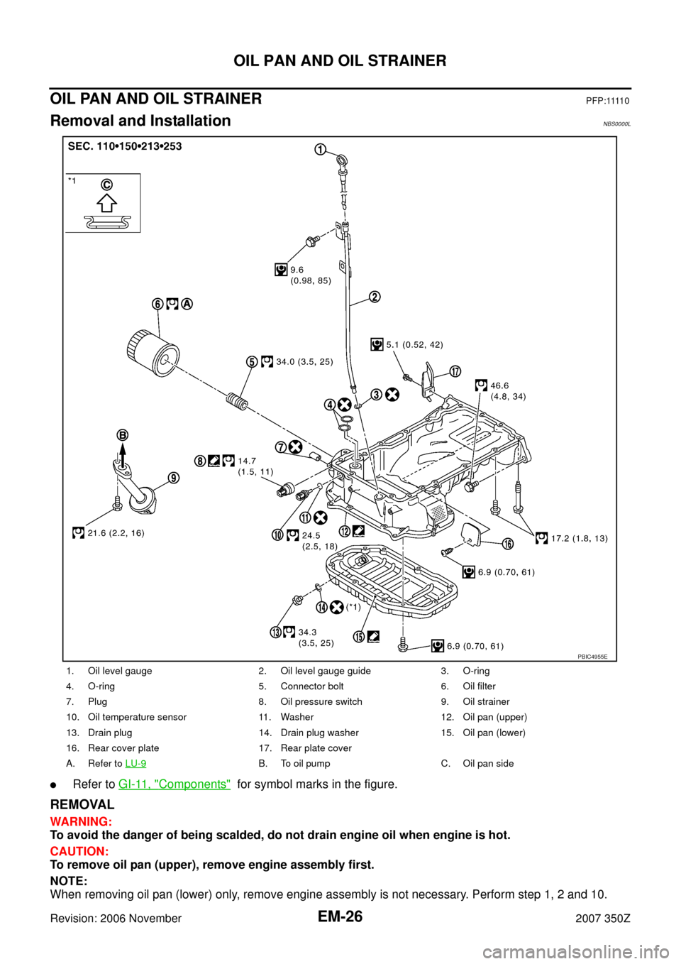
OIL PAN AND OIL STRAINERP F P : 1111 0
Removal and InstallationNBS0000L
�Refer to GI-11, "Components" for symbol marks in the figure.
REMOVAL
WARNING:
To avoid the danger of being scalded, do not drain engine oil when engine is hot.
CAUTION:
To remove oil pan (upper), remove engine assembly first.
NOTE:
When removing oil pan (lower) only, remove engine assembly is not necessary. Perform step 1, 2 and 10.
1. Oil level gauge 2. Oil level gauge guide 3. O-ring
4. O-ring 5. Connector bolt 6. Oil filter
7. Plug 8. Oil pressure switch 9. Oil strainer
10. Oil temperature sensor 11. Washer 12. Oil pan (upper)
13. Drain plug 14. Drain plug washer 15. Oil pan (lower)
16. Rear cover plate 17. Rear plate cover
A. Refer to LU-9
B. To oil pump C. Oil pan side
PBIC4955E
Page 27 of 148

OIL PAN AND OIL STRAINER
EM-27
C
D
E
F
G
H
I
J
K
L
MA
EM
Revision: 2006 November2007 350Z
1. Drain engine oil. Refer to LU-7, "Changing Engine Oil" .
CAUTION:
�Perform this step when engine is cold.
�Do not spill engine oil on drive belts.
2. Remove undercover with power tool.
3. Remove engine assembly from the vehicle, and separate front suspension member and transmission
from engine. Refer to EM-101, "
ENGINE ASSEMBLY" .
4. Lift the engine with hoist, and mount it onto widely use engine stand. Refer to EM-108, "
DISASSEMBLY" .
5. Remove alternator. Refer to SC-20, "
CHARGING SYSTEM" .
6. Remove starter motor. Refer to SC-8, "
STARTING SYSTEM" .
7. Remove idler pulley and bracket assembly. Refer to EM-53, "
TIMING CHAIN" .
8. Remove oil filter, as necessary. Refer to LU-9, "
OIL FILTER" .
9. Remove oil temperature sensor, as necessary.
10. Remove oil pan (lower) as follows:
a. Loosen mounting bolts with power tool in reverse order as
shown in the figure to remove.
b. Insert seal cutter (SST) between oil pan (upper) and oil pan
(lower).
CAUTION:
�Be careful not to damage the mating surfaces.
�Do not insert screwdriver, this will damage the mating
surface.
11. Remove oil strainer.
12. Remove rear cover plate.
13. Loosen mounting bolts with power tool in reverse order as
shown in the figure to remove oil pan (upper).
�I n s e r t s e a l c u t t e r [ S S T: K V 1 0 1111 0 0 ( J 3 7 2 2 8 ) ] b e t w e e n o i l
pan (upper) and cylinder block. Slide seal cutter by tapping on
the side of tool with hammer. Remove oil pan (upper).
CAUTION:
�Be careful not to damage mating surfaces.
�Do not insert screwdriver, this will damage the mating
surface.
: Engine front
PBIC4956E
SEM365E
: Engine frontPBIC4957E
Page 40 of 148

EM-40
ROCKER COVER
Revision: 2006 November2007 350Z
ROCKER COVERPFP:13264
Removal and InstallationNBS0000P
�Refer to GI-11, "Components" for symbol marks in the figure.
REMOVAL
1. Remove engine cover. Refer to EM-17, "INTAKE MANIFOLD COLLECTOR" .
2. Remove intake manifold collector. Refer to EM-17, "
INTAKE MANIFOLD COLLECTOR" .
3. Separate engine harness removing their brackets from rocker covers.
4. Remove ignition coil. Refer to EM-31, "
IGNITION COIL" .
1. PCV hose 2. Clamp 3. Ignition coil
4. Spark plug 5. PCV valve 6. O-ring
7. Rocker cover gasket (right bank) 8. Rocker cover (right bank) 9. O-ring
10. Camshaft position sensor (bank 1) 11.Exhaust valve timing control posi-
tion sensor (bank 1)12. Camshaft position sensor (bank 2)
13.Exhaust valve timing control position
sensor (bank 2)14. Rocker cover gasket (left bank) 15. Rocker cover (left bank)
16. PCV hose 17. Oil catcher 18. Oil filler cap
19. PCV hose
A. To intake manifold collector B. Refer to EM-40
C. Camshaft bracket side
D. To air duct
PBIC4964E
Page 41 of 148
ROCKER COVER
EM-41
C
D
E
F
G
H
I
J
K
L
MA
EM
Revision: 2006 November2007 350Z
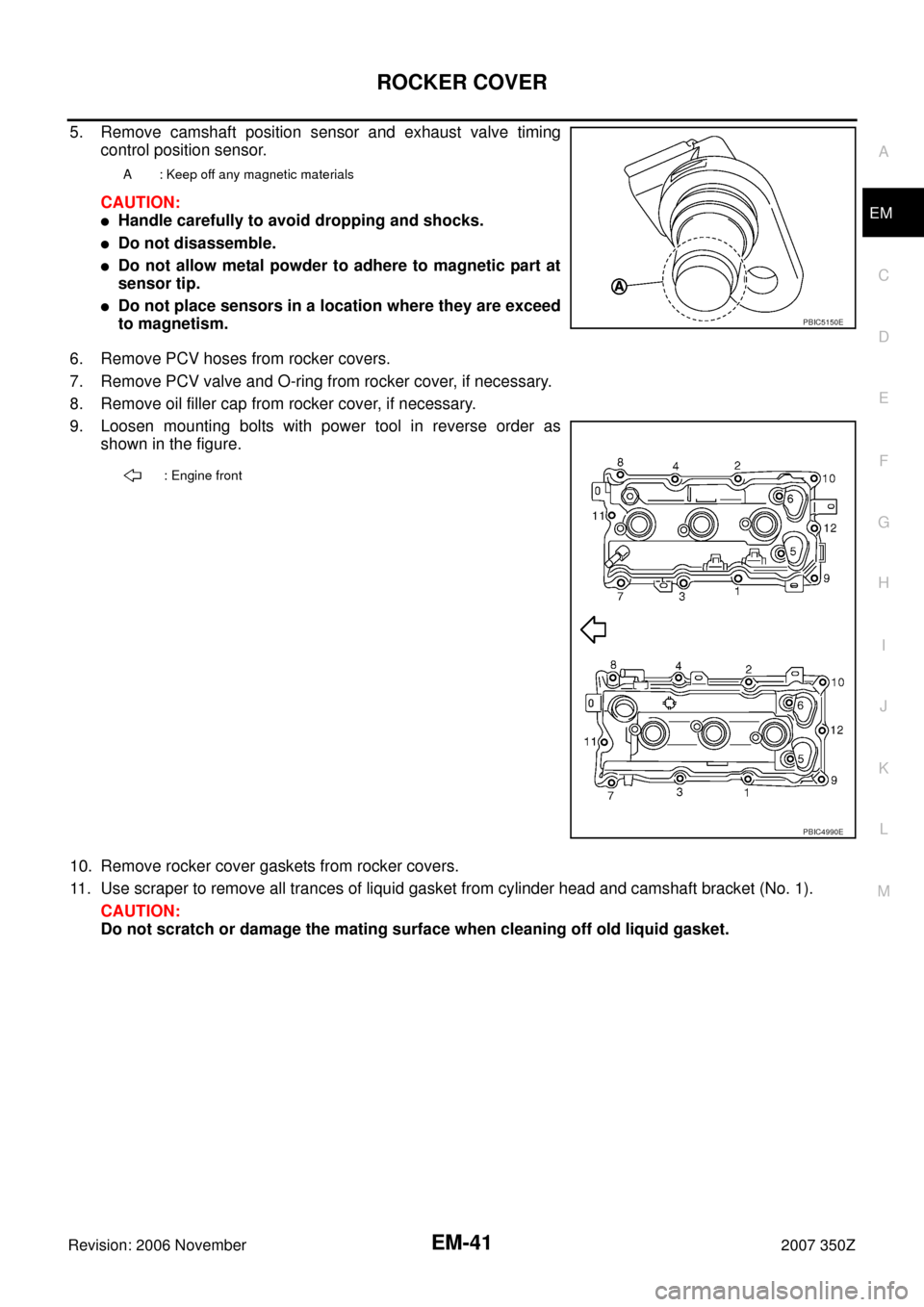
5. Remove camshaft position sensor and exhaust valve timing
control position sensor.
CAUTION:
�Handle carefully to avoid dropping and shocks.
�Do not disassemble.
�Do not allow metal powder to adhere to magnetic part at
sensor tip.
�Do not place sensors in a location where they are exceed
to magnetism.
6. Remove PCV hoses from rocker covers.
7. Remove PCV valve and O-ring from rocker cover, if necessary.
8. Remove oil filler cap from rocker cover, if necessary.
9. Loosen mounting bolts with power tool in reverse order as
shown in the figure.
10. Remove rocker cover gaskets from rocker covers.
11. Use scraper to remove all trances of liquid gasket from cylinder head and camshaft bracket (No. 1).
CAUTION:
Do not scratch or damage the mating surface when cleaning off old liquid gasket.
A : Keep off any magnetic materials
PBIC5150E
: Engine front
PBIC4990E
Page 72 of 148

EM-72
CAMSHAFT
Revision: 2006 November2007 350Z
CAMSHAFTPFP:13001
Removal and InstallationNBS0000T
�Refer to GI-11, "Components" for symbol marks in the figure.
REMOVAL
1. Remove front timing chain case, camshaft sprocket, and timing chain. Refer to EM-53, "TIMING CHAIN" .
1. Camshaft bracket (No. 3, 4) 2. Camshaft bracket (No. 2) 3. Seal washer
4. Camshaft bracket (No. 1) 5. Dowel pin 6. Camshaft (EXH) (right bank)
7. Camshaft signal plate (EXH) 8. Camshaft sensor bracket 9. Dowel pin
10. Camshaft signal plate (INT) 11. Camshaft (INT) (right bank) 12. Valve lifter
13. Cylinder head (right bank) 14. Plunger 15. Spring
16.Timing chain tensioner (secondary)
(right bank)17. Camshaft bracket (No. 3, 4) 18. Camshaft bracket (No. 2)
19. Camshaft bracket (No. 1) 20. Camshaft signal plate (INT) 21. Camshaft signal plate (EXH)
22. Camshaft sensor bracket 23. Cylinder head (left bank) 24.Timing chain tensioner (secondary)
(left bank)
25. Camshaft (EXH) (left bank) 26. Camshaft (INT) (left bank)
A. Refer to EM-77
PBIC4983E
Page 73 of 148
CAMSHAFT
EM-73
C
D
E
F
G
H
I
J
K
L
MA
EM
Revision: 2006 November2007 350Z
2. Remove fuel sub tube. Refer to EM-34, "FUEL INJECTOR AND FUEL TUBE" .
3. Remove camshaft sensor bracket bolts in reverse order as
shown in the figure.
4. Remove intake and exhaust camshaft brackets.
�Mark camshafts, camshaft brackets and bolts so they are placed in the same position and direction for
installation.
�Equally loosen camshaft bracket bolts in several steps in
reverse order as shown in the figure.
5. Remove camshaft.
6. Remove valve lifter.
�Identify installation positions, and store them without mixing them up.
7. Remove timing chain tensioner (secondary) (1) from cylinder
head.
�Remove timing chain tensioner (secondary) (1) with its stop-
per pin (C) attached.
NOTE:
Stopper pin (C) was attached when timing chain (secondary)
was removed.
: Engine front
PBIC5054E
PBIC2050E
A : Right bank
B : Left bank
PBIC5045E
Page 79 of 148

CAMSHAFT
EM-79
C
D
E
F
G
H
I
J
K
L
MA
EM
Revision: 2006 November2007 350Z
5. Tighten camshaft bracket bolts in the following steps, in numeri-
cal order as shown in the figure.
a. Tighten No. 7 to 10 in numerical order as shown.
b. Tighten No. 1 to 6 in numerical order as shown.
c. Tighten No. 1 to 10 in numerical order as shown.
d. Tighten No. 1 to 10 in numerical order as shown.
CAUTION:
After tightening mounting bolts of camshaft brackets (No.
1), be sure to wipe off excessive liquid gasket from the
parts list below.
�Mating surface of rocker cover
�Mating surface of rear timing chain case
6. Inspect and adjust the valve clearance. Refer to EM-80, "
Valve Clearance" .
7. Install camshaft sensor bracket.
�Tighten camshaft sensor bracket bolts in numerical order as
shown in the figure.
8. Install in the reverse order of removal after this step.
INSPECTION AFTER INSTALLATION
Inspection of Camshaft Sprocket (INT) Oil Groove
CAUTION:
�Perform this inspection only when DTC P0011 or P0021 are detected in self-diagnostic results of
CONSULT-III and it is directed according to inspection procedure of EC section. Refer to EC-81,
"TROUBLE DIAGNOSIS" .
�Check when engine is cold so as to prevent burns from any splashing engine oil.
1. Check the engine oil level. Refer to LU-6, "
ENGINE OIL" .
2. Perform the following procedure so as to prevent the engine from being unintentionally started while
checking.
a. Release fuel pressure. Refer to EC-79, "
FUEL PRESSURE RELEASE" .
b. Disconnect ignition coil and injector harness connectors.
3. Remove intake valve timing control solenoid valve. Refer to EM-72, "
CAMSHAFT" . : 1.96 N·m (0.2 kg-m, 17 in-lb)
: 1.96 N·m (0.2 kg-m, 17 in-lb)
: 5.88 N·m (0.6 kg-m, 52 in-lb)
: 10.4 N·m (1.1 kg-m, 92 in-lb)
PBIC2050E
: Engine front
PBIC5054E
Page 107 of 148
CYLINDER BLOCK
EM-107
C
D
E
F
G
H
I
J
K
L
MA
EM
Revision: 2006 November2007 350Z
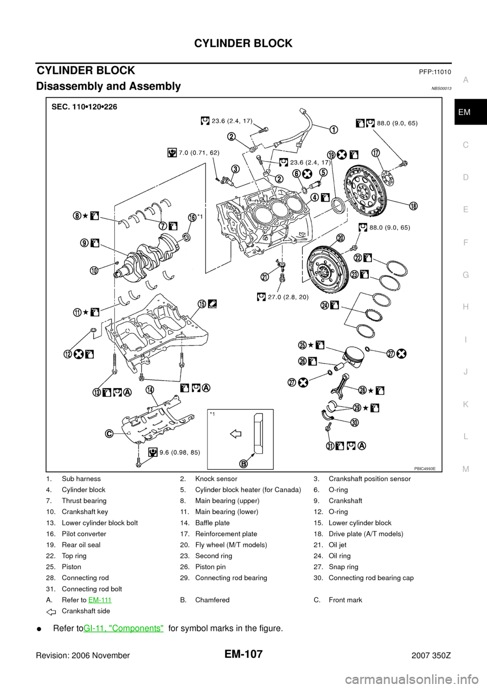
CYLINDER BLOCKPFP:11010
Disassembly and AssemblyNBS00013
�Refer toGI-11, "Components" for symbol marks in the figure.
1. Sub harness 2. Knock sensor 3. Crankshaft position sensor
4. Cylinder block 5. Cylinder block heater (for Canada) 6. O-ring
7. Thrust bearing 8. Main bearing (upper) 9. Crankshaft
10. Crankshaft key 11. Main bearing (lower) 12. O-ring
13. Lower cylinder block bolt 14. Baffle plate 15. Lower cylinder block
16. Pilot converter 17. Reinforcement plate 18. Drive plate (A/T models)
19. Rear oil seal 20. Fly wheel (M/T models) 21. Oil jet
22. Top ring 23. Second ring 24. Oil ring
25. Piston 26. Piston pin 27. Snap ring
28. Connecting rod 29. Connecting rod bearing 30. Connecting rod bearing cap
31. Connecting rod bolt
A. Refer to E M - 111
B. Chamfered C. Front mark
Crankshaft side
PBIC4993E