Page 103 of 148

ENGINE ASSEMBLY
EM-103
C
D
E
F
G
H
I
J
K
L
MA
EM
Revision: 2006 November2007 350Z
1. Remove passenger-side kicking plate inner, dash side finisher, and instrument passenger panel lower.
Refer to EI-35, "
BODY SIDE TRIM" and IP-10, "INSTRUMENT PANEL ASSEMBLY" .
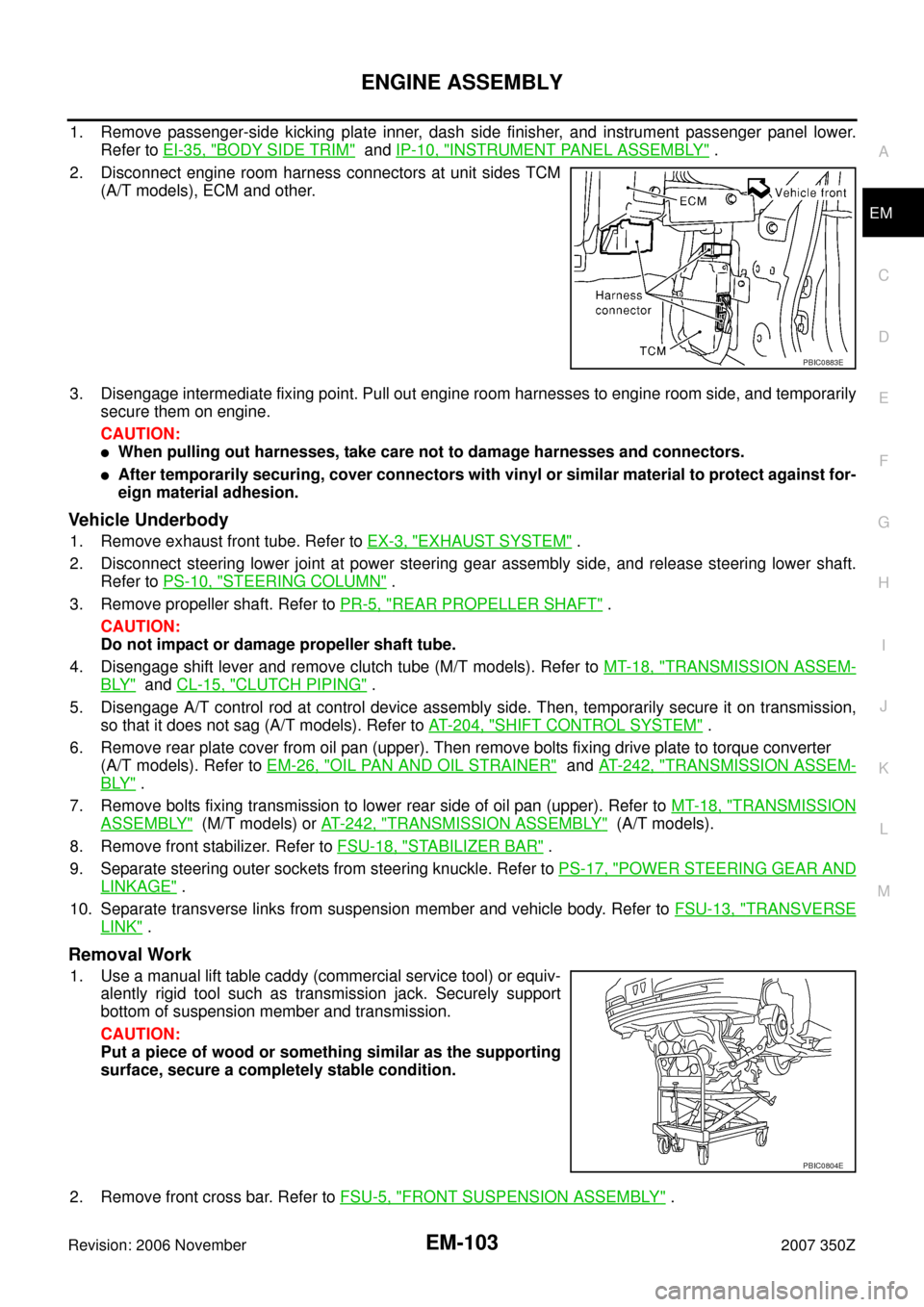
2. Disconnect engine room harness connectors at unit sides TCM
(A/T models), ECM and other.
3. Disengage intermediate fixing point. Pull out engine room harnesses to engine room side, and temporarily
secure them on engine.
CAUTION:
�When pulling out harnesses, take care not to damage harnesses and connectors.
�After temporarily securing, cover connectors with vinyl or similar material to protect against for-
eign material adhesion.
Vehicle Underbody
1. Remove exhaust front tube. Refer to EX-3, "EXHAUST SYSTEM" .
2. Disconnect steering lower joint at power steering gear assembly side, and release steering lower shaft.
Refer to PS-10, "
STEERING COLUMN" .
3. Remove propeller shaft. Refer to PR-5, "
REAR PROPELLER SHAFT" .
CAUTION:
Do not impact or damage propeller shaft tube.
4. Disengage shift lever and remove clutch tube (M/T models). Refer to MT-18, "
TRANSMISSION ASSEM-
BLY" and CL-15, "CLUTCH PIPING" .
5. Disengage A/T control rod at control device assembly side. Then, temporarily secure it on transmission,
so that it does not sag (A/T models). Refer to AT- 2 0 4 , "
SHIFT CONTROL SYSTEM" .
6. Remove rear plate cover from oil pan (upper). Then remove bolts fixing drive plate to torque converter
(A/T models). Refer to EM-26, "
OIL PAN AND OIL STRAINER" and AT- 2 4 2 , "TRANSMISSION ASSEM-
BLY" .
7. Remove bolts fixing transmission to lower rear side of oil pan (upper). Refer to MT-18, "
TRANSMISSION
ASSEMBLY" (M/T models) or AT- 2 4 2 , "TRANSMISSION ASSEMBLY" (A/T models).
8. Remove front stabilizer. Refer to FSU-18, "
STABILIZER BAR" .
9. Separate steering outer sockets from steering knuckle. Refer to PS-17, "
POWER STEERING GEAR AND
LINKAGE" .
10. Separate transverse links from suspension member and vehicle body. Refer to FSU-13, "
TRANSVERSE
LINK" .
Removal Work
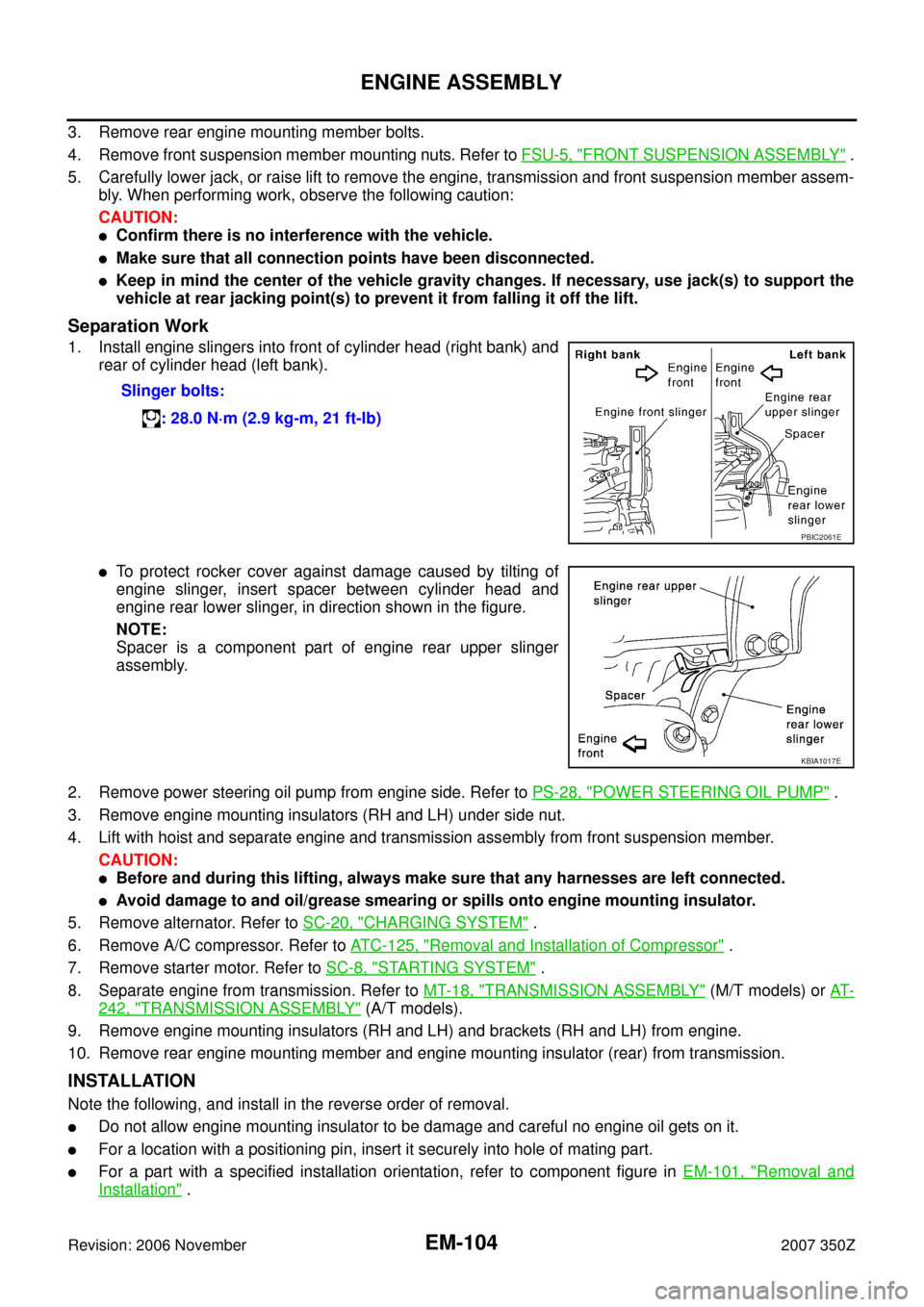
1. Use a manual lift table caddy (commercial service tool) or equiv-
alently rigid tool such as transmission jack. Securely support
bottom of suspension member and transmission.
CAUTION:
Put a piece of wood or something similar as the supporting
surface, secure a completely stable condition.
2. Remove front cross bar. Refer to FSU-5, "
FRONT SUSPENSION ASSEMBLY" .
PBIC0883E
PBIC0804E
Page 104 of 148

EM-104
ENGINE ASSEMBLY
Revision: 2006 November2007 350Z
3. Remove rear engine mounting member bolts.
4. Remove front suspension member mounting nuts. Refer to FSU-5, "
FRONT SUSPENSION ASSEMBLY" .
5. Carefully lower jack, or raise lift to remove the engine, transmission and front suspension member assem-
bly. When performing work, observe the following caution:
CAUTION:
�Confirm there is no interference with the vehicle.
�Make sure that all connection points have been disconnected.
�Keep in mind the center of the vehicle gravity changes. If necessary, use jack(s) to support the
vehicle at rear jacking point(s) to prevent it from falling it off the lift.
Separation Work
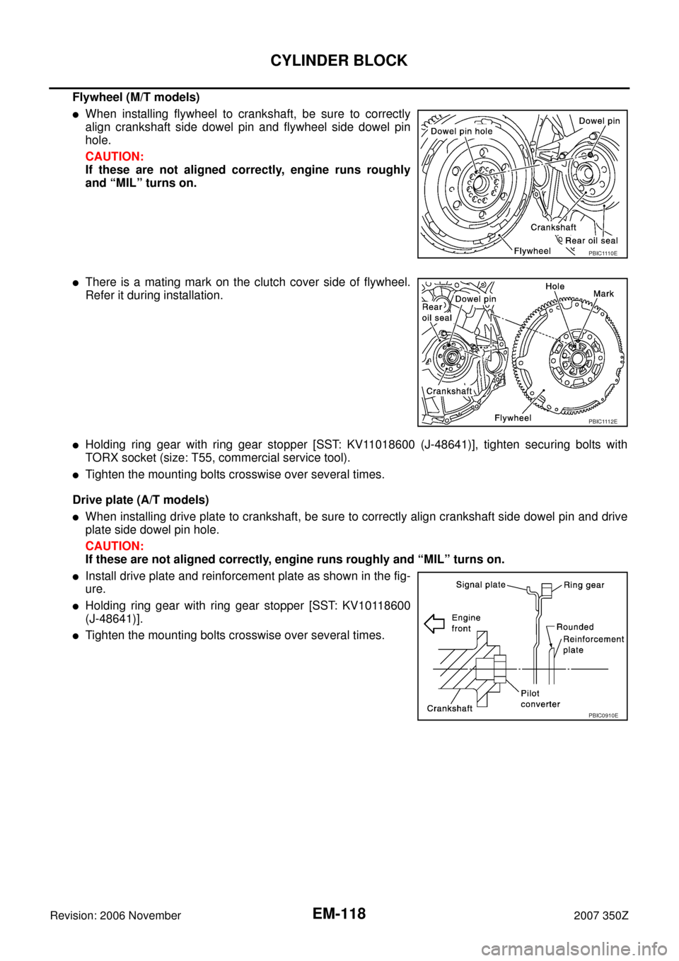
1. Install engine slingers into front of cylinder head (right bank) and
rear of cylinder head (left bank).
�To protect rocker cover against damage caused by tilting of
engine slinger, insert spacer between cylinder head and
engine rear lower slinger, in direction shown in the figure.
NOTE:
Spacer is a component part of engine rear upper slinger
assembly.
2. Remove power steering oil pump from engine side. Refer to PS-28, "
POWER STEERING OIL PUMP" .
3. Remove engine mounting insulators (RH and LH) under side nut.
4. Lift with hoist and separate engine and transmission assembly from front suspension member.
CAUTION:
�Before and during this lifting, always make sure that any harnesses are left connected.
�Avoid damage to and oil/grease smearing or spills onto engine mounting insulator.
5. Remove alternator. Refer to SC-20, "
CHARGING SYSTEM" .
6. Remove A/C compressor. Refer to ATC-125, "
Removal and Installation of Compressor" .
7. Remove starter motor. Refer to SC-8, "
STARTING SYSTEM" .
8. Separate engine from transmission. Refer to MT-18, "
TRANSMISSION ASSEMBLY" (M/T models) or AT-
242, "TRANSMISSION ASSEMBLY" (A/T models).
9. Remove engine mounting insulators (RH and LH) and brackets (RH and LH) from engine.
10. Remove rear engine mounting member and engine mounting insulator (rear) from transmission.
INSTALLATION
Note the following, and install in the reverse order of removal.
�Do not allow engine mounting insulator to be damage and careful no engine oil gets on it.
�For a location with a positioning pin, insert it securely into hole of mating part.
�For a part with a specified installation orientation, refer to component figure in EM-101, "Removal and
Installation" . Slinger bolts:
: 28.0 N·m (2.9 kg-m, 21 ft-lb)
PBIC2061E
KBIA1017E
Page 118 of 148

EM-118
CYLINDER BLOCK
Revision: 2006 November2007 350Z
Flywheel (M/T models)
�When installing flywheel to crankshaft, be sure to correctly
align crankshaft side dowel pin and flywheel side dowel pin
hole.
CAUTION:
If these are not aligned correctly, engine runs roughly
and “MIL” turns on.
�There is a mating mark on the clutch cover side of flywheel.
Refer it during installation.
�Holding ring gear with ring gear stopper [SST: KV11018600 (J-48641)], tighten securing bolts with
TORX socket (size: T55, commercial service tool).
�Tighten the mounting bolts crosswise over several times.
Drive plate (A/T models)
�When installing drive plate to crankshaft, be sure to correctly align crankshaft side dowel pin and drive
plate side dowel pin hole.
CAUTION:
If these are not aligned correctly, engine runs roughly and “MIL” turns on.
�Install drive plate and reinforcement plate as shown in the fig-
ure.
�Holding ring gear with ring gear stopper [SST: KV10118600
(J-48641)].
�Tighten the mounting bolts crosswise over several times.
PBIC1110E
PBIC1112E
PBIC0910E