Page 664 of 720
EC-664
DTC P2A00, P2A03 A/F SENSOR 1
Revision: 2006 November2007 350Z
Specification data are reference values and are measured between each terminal and ground.
Pulse signal is measured by CONSULT-III.
CAUTION:
Do not use ECM ground terminals when measuring input/output voltage. Doing so may result in dam-
age to the ECM's transistor. Use a ground other than ECM terminals, such as the ground.
: Average voltage for pulse signal (Actual pulse signal can be confirmed by oscilloscope.)TER-
MINAL
NO.WIRE
COLORITEM CONDITION DATA (DC Voltage)
5GY/LA/F sensor 1 heater
(bank 2)[Engine is running]
�Warm-up condition
�Idle speed
(More than 140 seconds after starting
engine)2.9 - 8.8
65 PU A/F sensor 1 (bank 2)[Ignition switch: ON]2.2V
66 LG A/F sensor 1 (bank 2)[Ignition switch: ON]
�Warm-up condition
�Engine speed: 2,000 rpm1.8V
Output voltage varies with air
fuel ratio.
PBIB3538E
Page 666 of 720
EC-666
DTC P2A00, P2A03 A/F SENSOR 1
Revision: 2006 November2007 350Z
2. RETIGHTEN AIR FUEL RATIO SENSOR 1
1. Loosen and retighten the air fuel ratio (A/F) sensor 1.
>> GO TO 3.
3. CHECK FOR INTAKE AIR LEAK
1. Start engine and run it at idle.
2. Listen for an intake air leak after the mass air flow sensor.
OK or NG
OK >> GO TO 4.
NG >> Repair or replace.
1. A/F sensor 1 (bank1) 2. A/F sensor 1 (bank 2)
:Vehicle front
Tightening torque: 50 N-m (5.1 kg-m, 37 ft-lb)
PBIB3517E
Page 667 of 720
DTC P2A00, P2A03 A/F SENSOR 1
EC-667
C
D
E
F
G
H
I
J
K
L
MA
EC
Revision: 2006 November2007 350Z
4. CLEAR THE SELF-LEARNING DATA
With CONSULT-III
1. Start engine and warm it up to normal operating temperature.
2. Select “SELF-LEARNING CONT” in “WORK SUPPORT” mode with CONSULT-III.
3. Clear the self-learning control coefficient by touching “CLEAR”.
4. Run engine for at least 10 minutes at idle speed.
Is the 1st trip DTC P0171, P0172, P0174 or P0175 detected?
Is it difficult to start engine?
Without CONSULT-III
1. Start engine and warm it up to normal operating temperature.
2. Turn ignition switch OFF.
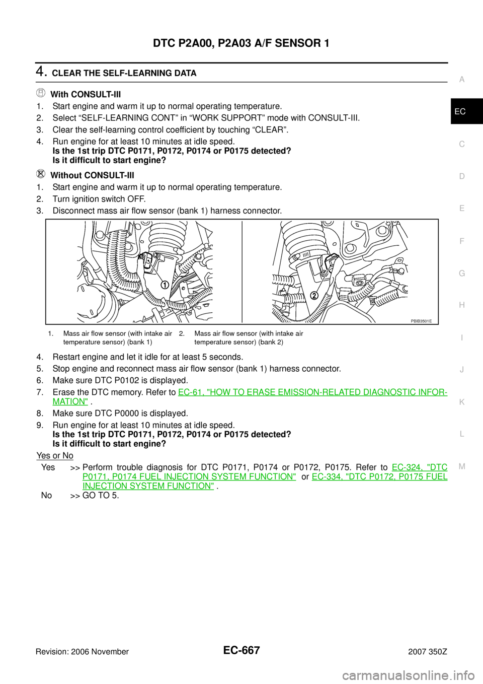
3. Disconnect mass air flow sensor (bank 1) harness connector.
4. Restart engine and let it idle for at least 5 seconds.
5. Stop engine and reconnect mass air flow sensor (bank 1) harness connector.
6. Make sure DTC P0102 is displayed.
7. Erase the DTC memory. Refer to EC-61, "
HOW TO ERASE EMISSION-RELATED DIAGNOSTIC INFOR-
MATION" .
8. Make sure DTC P0000 is displayed.
9. Run engine for at least 10 minutes at idle speed.
Is the 1st trip DTC P0171, P0172, P0174 or P0175 detected?
Is it difficult to start engine?
Ye s o r N o
Yes >> Perform trouble diagnosis for DTC P0171, P0174 or P0172, P0175. Refer to EC-324, "DTC
P0171, P0174 FUEL INJECTION SYSTEM FUNCTION" or EC-334, "DTC P0172, P0175 FUEL
INJECTION SYSTEM FUNCTION" .
No >> GO TO 5.
1. Mass air flow sensor (with intake air
temperature sensor) (bank 1)2. Mass air flow sensor (with intake air
temperature sensor) (bank 2)
PBIB3501E
Page 669 of 720
DTC P2A00, P2A03 A/F SENSOR 1
EC-669
C
D
E
F
G
H
I
J
K
L
MA
EC
Revision: 2006 November2007 350Z
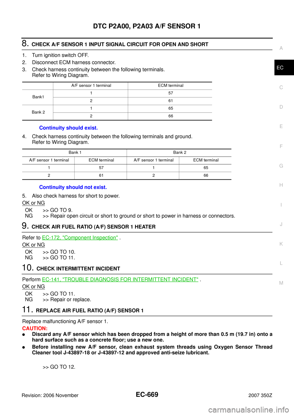
8. CHECK A/F SENSOR 1 INPUT SIGNAL CIRCUIT FOR OPEN AND SHORT
1. Turn ignition switch OFF.
2. Disconnect ECM harness connector.
3. Check harness continuity between the following terminals.
Refer to Wiring Diagram.
4. Check harness continuity between the following terminals and ground.
Refer to Wiring Diagram.
5. Also check harness for short to power.
OK or NG
OK >> GO TO 9.
NG >> Repair open circuit or short to ground or short to power in harness or connectors.
9. CHECK AIR FUEL RATIO (A/F) SENSOR 1 HEATER
Refer to EC-172, "
Component Inspection" .
OK or NG
OK >> GO TO 10.
NG >> GO TO 11.
10. CHECK INTERMITTENT INCIDENT
Perform EC-141, "
TROUBLE DIAGNOSIS FOR INTERMITTENT INCIDENT" .
OK or NG
OK >> GO TO 11.
NG >> Repair or replace.
11 . REPLACE AIR FUEL RATIO (A/F) SENSOR 1
Replace malfunctioning A/F sensor 1.
CAUTION:
�Discard any A/F sensor which has been dropped from a height of more than 0.5 m (19.7 in) onto a
hard surface such as a concrete floor; use a new one.
�Before installing new A/F sensor, clean exhaust system threads using Oxygen Sensor Thread
Cleaner tool J-43897-18 or J-43897-12 and approved anti-seize lubricant.
>> GO TO 12.
A/F sensor 1 terminal ECM terminal
Bank1157
261
Bank 2165
266
Continuity should exist.
Bank 1 Bank 2
A/F sensor 1 terminal ECM terminal A/F sensor 1 terminal ECM terminal
157165
261266
Continuity should not exist.
Page 670 of 720
EC-670
DTC P2A00, P2A03 A/F SENSOR 1
Revision: 2006 November2007 350Z
12. CONFIRM A/F ADJUSTMENT DATA
1. Turn ignition switch ON.
2. Select “A/F ADJ-B1” and “A/F ADJ-B2” in “DATA MONITOR” mode with CONSULT-III.
3. Make sure that “0.000” is displayed on CONSULT-III screen.
OK or NG
OK >>INSPECTION END
NG >> GO TO 13.
13. CLEAR THE SELF-LEARNING DATA.
With CONSULT-III
1. Start engine and warm it up to normal operating temperature.
2. Select “SELF-LEARNING CONT” in “WORK SUPPORT” mode with CONSULT-III.
3. Clear the self-learning control coefficient by touching “CLEAR”.
Without CONSULT-III
1. Start engine and warm it up to normal operating temperature.
2. Turn ignition switch OFF.
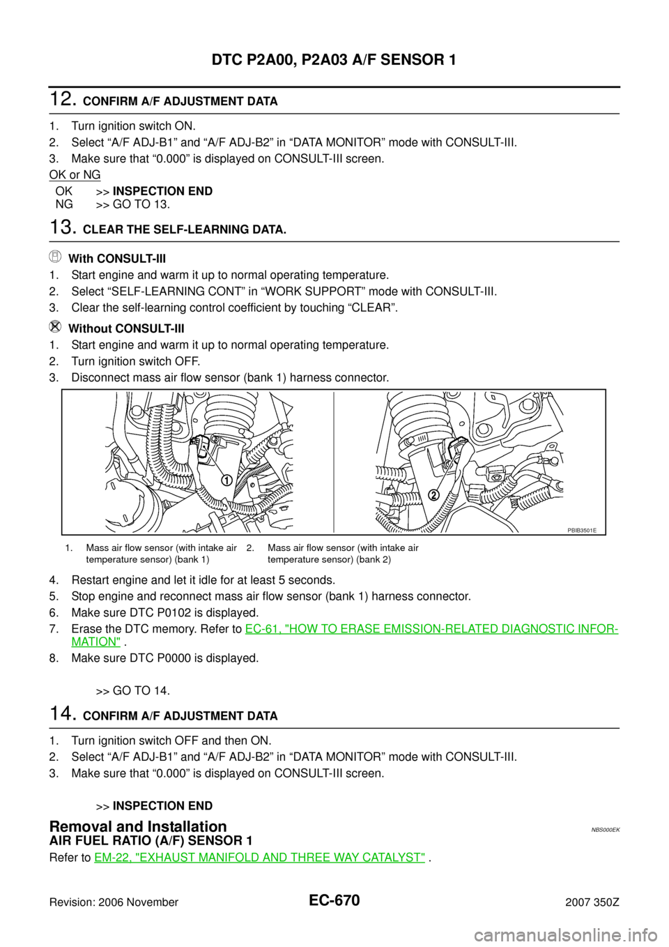
3. Disconnect mass air flow sensor (bank 1) harness connector.
4. Restart engine and let it idle for at least 5 seconds.
5. Stop engine and reconnect mass air flow sensor (bank 1) harness connector.
6. Make sure DTC P0102 is displayed.
7. Erase the DTC memory. Refer to EC-61, "
HOW TO ERASE EMISSION-RELATED DIAGNOSTIC INFOR-
MATION" .
8. Make sure DTC P0000 is displayed.
>> GO TO 14.
14. CONFIRM A/F ADJUSTMENT DATA
1. Turn ignition switch OFF and then ON.
2. Select “A/F ADJ-B1” and “A/F ADJ-B2” in “DATA MONITOR” mode with CONSULT-III.
3. Make sure that “0.000” is displayed on CONSULT-III screen.
>>INSPECTION END
Removal and InstallationNBS000EK
AIR FUEL RATIO (A/F) SENSOR 1
Refer to EM-22, "EXHAUST MANIFOLD AND THREE WAY CATALYST" .
1. Mass air flow sensor (with intake air
temperature sensor) (bank 1)2. Mass air flow sensor (with intake air
temperature sensor) (bank 2)
PBIB3501E
Page 686 of 720
EC-686
FUEL INJECTOR
Revision: 2006 November2007 350Z
FUEL INJECTORPFP:16600
Component DescriptionNBS000HQ
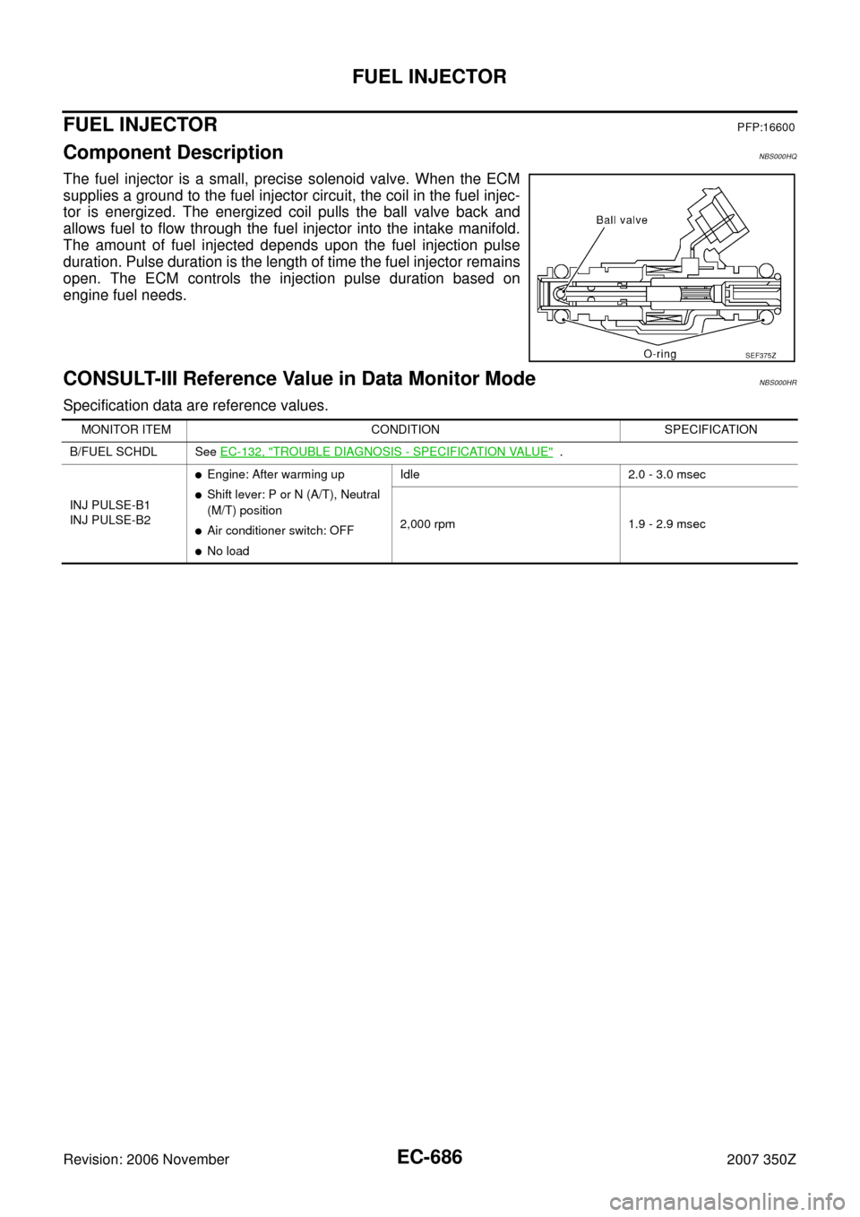
The fuel injector is a small, precise solenoid valve. When the ECM
supplies a ground to the fuel injector circuit, the coil in the fuel injec-
tor is energized. The energized coil pulls the ball valve back and
allows fuel to flow through the fuel injector into the intake manifold.
The amount of fuel injected depends upon the fuel injection pulse
duration. Pulse duration is the length of time the fuel injector remains
open. The ECM controls the injection pulse duration based on
engine fuel needs.
CONSULT-III Reference Value in Data Monitor ModeNBS000HR
Specification data are reference values.
SEF375Z
MONITOR ITEM CONDITION SPECIFICATION
B/FUEL SCHDL See EC-132, "
TROUBLE DIAGNOSIS - SPECIFICATION VALUE" .
INJ PULSE-B1
INJ PULSE-B2
�Engine: After warming up
�Shift lever: P or N (A/T), Neutral
(M/T) position
�Air conditioner switch: OFF
�No loadIdle 2.0 - 3.0 msec
2,000 rpm 1.9 - 2.9 msec
Page 687 of 720
FUEL INJECTOR
EC-687
C
D
E
F
G
H
I
J
K
L
MA
EC
Revision: 2006 November2007 350Z
Wiring DiagramNBS000HS
TBWT1678E
Page 688 of 720
EC-688
FUEL INJECTOR
Revision: 2006 November2007 350Z
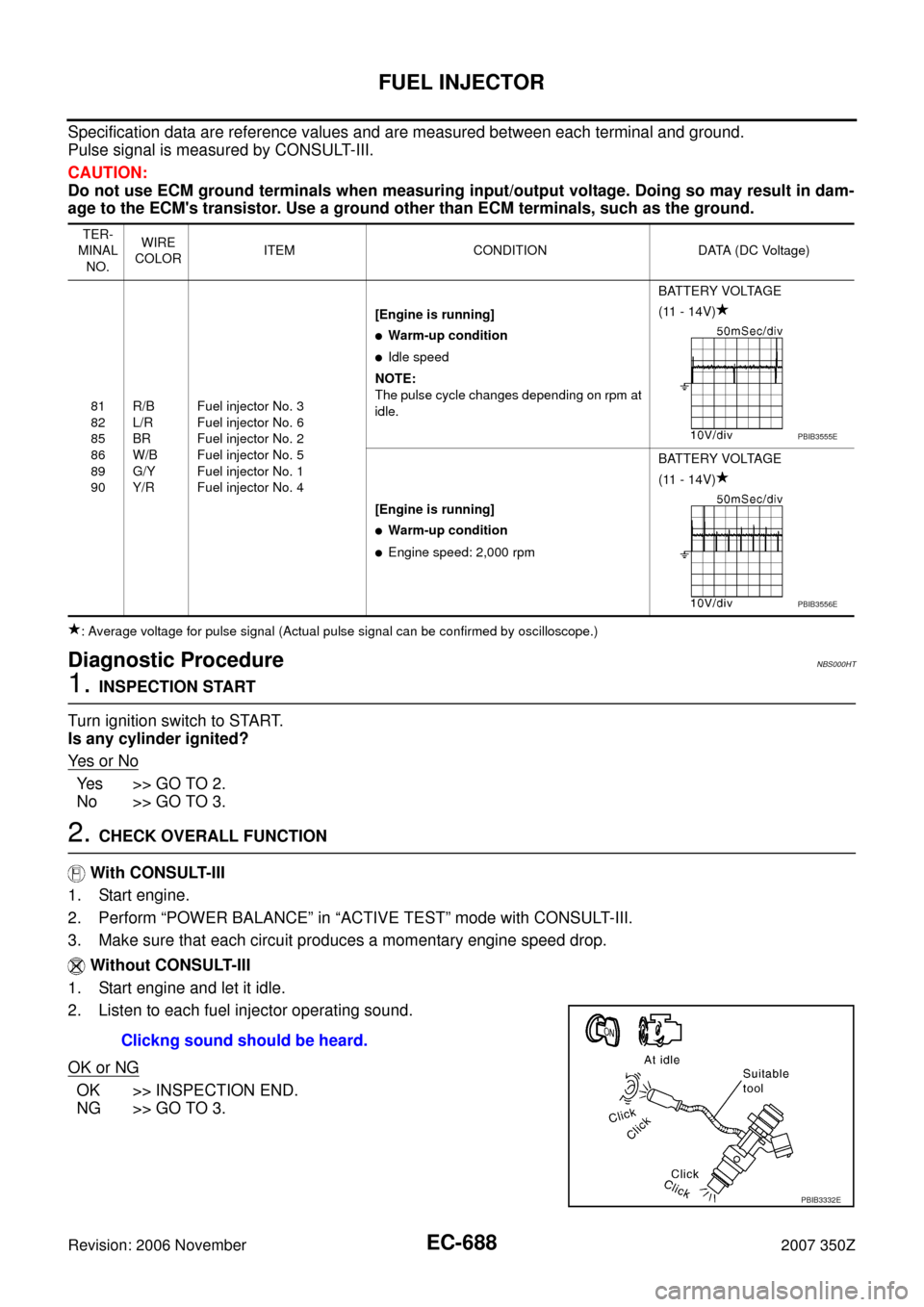
Specification data are reference values and are measured between each terminal and ground.
Pulse signal is measured by CONSULT-III.
CAUTION:
Do not use ECM ground terminals when measuring input/output voltage. Doing so may result in dam-
age to the ECM's transistor. Use a ground other than ECM terminals, such as the ground.
: Average voltage for pulse signal (Actual pulse signal can be confirmed by oscilloscope.)
Diagnostic ProcedureNBS000HT
1. INSPECTION START
Turn ignition switch to START.
Is any cylinder ignited?
Ye s o r N o
Yes >> GO TO 2.
No >> GO TO 3.
2. CHECK OVERALL FUNCTION
With CONSULT-III
1. Start engine.
2. Perform “POWER BALANCE” in “ACTIVE TEST” mode with CONSULT-III.
3. Make sure that each circuit produces a momentary engine speed drop.
Without CONSULT-III
1. Start engine and let it idle.
2. Listen to each fuel injector operating sound.
OK or NG
OK >> INSPECTION END.
NG >> GO TO 3.
TER-
MINAL
NO.WIRE
COLORITEM CONDITION DATA (DC Voltage)
81
82
85
86
89
90R/B
L/R
BR
W/B
G/Y
Y/RFuel injector No. 3
Fuel injector No. 6
Fuel injector No. 2
Fuel injector No. 5
Fuel injector No. 1
Fuel injector No. 4[Engine is running]
�Warm-up condition
�Idle speed
NOTE:
The pulse cycle changes depending on rpm at
idle.BATTERY VOLTAGE
(11 - 14V)
[Engine is running]
�Warm-up condition
�Engine speed: 2,000 rpmBATTERY VOLTAGE
(11 - 14V)
PBIB3555E
PBIB3556E
Clickng sound should be heard.
PBIB3332E